EP0068779A1 - Appareil photographique et système de contrôle d'exposition - Google Patents
Appareil photographique et système de contrôle d'exposition Download PDFInfo
- Publication number
- EP0068779A1 EP0068779A1 EP82303221A EP82303221A EP0068779A1 EP 0068779 A1 EP0068779 A1 EP 0068779A1 EP 82303221 A EP82303221 A EP 82303221A EP 82303221 A EP82303221 A EP 82303221A EP 0068779 A1 EP0068779 A1 EP 0068779A1
- Authority
- EP
- European Patent Office
- Prior art keywords
- strobe
- scene
- trajectory
- exposure
- aperture
- Prior art date
- Legal status (The legal status is an assumption and is not a legal conclusion. Google has not performed a legal analysis and makes no representation as to the accuracy of the status listed.)
- Granted
Links
- 238000010791 quenching Methods 0.000 claims abstract description 66
- 238000010304 firing Methods 0.000 claims abstract description 65
- 230000002596 correlated effect Effects 0.000 claims abstract description 21
- 230000001276 controlling effect Effects 0.000 claims abstract description 12
- 230000007246 mechanism Effects 0.000 claims description 58
- 238000000034 method Methods 0.000 claims description 35
- 238000005286 illumination Methods 0.000 claims description 28
- 230000000875 corresponding effect Effects 0.000 claims description 20
- 238000006073 displacement reaction Methods 0.000 claims description 18
- 230000005540 biological transmission Effects 0.000 claims description 16
- 230000006870 function Effects 0.000 claims description 15
- 230000000694 effects Effects 0.000 claims description 9
- 230000000171 quenching effect Effects 0.000 claims description 7
- 230000003247 decreasing effect Effects 0.000 claims description 5
- 230000000977 initiatory effect Effects 0.000 claims description 5
- 230000001105 regulatory effect Effects 0.000 claims description 3
- 238000012512 characterization method Methods 0.000 claims 1
- 230000004044 response Effects 0.000 description 24
- 230000033001 locomotion Effects 0.000 description 16
- 230000008569 process Effects 0.000 description 7
- 238000013459 approach Methods 0.000 description 5
- 230000008901 benefit Effects 0.000 description 5
- 230000007423 decrease Effects 0.000 description 5
- 230000001133 acceleration Effects 0.000 description 4
- 230000008859 change Effects 0.000 description 4
- 230000003287 optical effect Effects 0.000 description 4
- 230000008672 reprogramming Effects 0.000 description 4
- 230000002441 reversible effect Effects 0.000 description 4
- 239000011159 matrix material Substances 0.000 description 3
- 230000000903 blocking effect Effects 0.000 description 2
- 238000011161 development Methods 0.000 description 2
- 230000018109 developmental process Effects 0.000 description 2
- 238000010586 diagram Methods 0.000 description 2
- 238000007687 exposure technique Methods 0.000 description 2
- 230000002452 interceptive effect Effects 0.000 description 2
- 238000011022 operating instruction Methods 0.000 description 2
- 230000009471 action Effects 0.000 description 1
- 230000002411 adverse Effects 0.000 description 1
- 230000000295 complement effect Effects 0.000 description 1
- 238000010276 construction Methods 0.000 description 1
- 238000012937 correction Methods 0.000 description 1
- 238000013461 design Methods 0.000 description 1
- 238000009792 diffusion process Methods 0.000 description 1
- 230000003292 diminished effect Effects 0.000 description 1
- 238000003384 imaging method Methods 0.000 description 1
- 230000010354 integration Effects 0.000 description 1
- 238000005259 measurement Methods 0.000 description 1
- 238000012986 modification Methods 0.000 description 1
- 230000004048 modification Effects 0.000 description 1
- 238000012544 monitoring process Methods 0.000 description 1
- 238000005457 optimization Methods 0.000 description 1
- 238000012545 processing Methods 0.000 description 1
- 229940018489 pronto Drugs 0.000 description 1
- 230000002829 reductive effect Effects 0.000 description 1
- 238000007665 sagging Methods 0.000 description 1
- 238000007789 sealing Methods 0.000 description 1
- 239000000758 substrate Substances 0.000 description 1
- 230000000153 supplemental effect Effects 0.000 description 1
- 238000012546 transfer Methods 0.000 description 1
- 230000001960 triggered effect Effects 0.000 description 1
- 238000004804 winding Methods 0.000 description 1
Images


Classifications
-
- G—PHYSICS
- G03—PHOTOGRAPHY; CINEMATOGRAPHY; ANALOGOUS TECHNIQUES USING WAVES OTHER THAN OPTICAL WAVES; ELECTROGRAPHY; HOLOGRAPHY
- G03B—APPARATUS OR ARRANGEMENTS FOR TAKING PHOTOGRAPHS OR FOR PROJECTING OR VIEWING THEM; APPARATUS OR ARRANGEMENTS EMPLOYING ANALOGOUS TECHNIQUES USING WAVES OTHER THAN OPTICAL WAVES; ACCESSORIES THEREFOR
- G03B7/00—Control of exposure by setting shutters, diaphragms or filters, separately or conjointly
- G03B7/08—Control effected solely on the basis of the response, to the intensity of the light received by the camera, of a built-in light-sensitive device
- G03B7/091—Digital circuits
Definitions
- the present invention relates to the field-of photography and, more specifically, to automatic exposure control systems and methods incorporating a microcomputer for developing a'film exposure strategy or program based on certain pre-exposure scene information inputs and for, thereafter, controlling operation of selected system components during the film exposure phase to carry out the developed strategy.
- a sonar ranging system measures camera-to-scene distance and sets the objective lens at the correct focus position, the film unit is automatically exposed in accordance with the scene brightness level measured by a photocell circuit, and then the exposed film unit is advanced automatically between a pair of pressure applying rollers to initiate a well-known development and diffusion transfer process.
- These cameras also are configured for automatic flash mode operation-employing flashbars (an array of flash- bulbs) and/or strobe units. Not only do such cameras operate in a conventional flash mode when ambient light is very low so that exposure illumination is provided primarily by the artificial light source, but they also operate in an automatic fill flash mode at higher ambient light levels. In this.mode, artificial illumination is mixed proportionally with ambient light for the-purpose of eliminating or softening shadows, or for adding additional illumination to dark areas of the scene to bring out the details thereof.
- transmission of image forming light to the film plane is controlled by a dynamic aperture scanning shutter which employs an integrated blade mechanism having a pair of counter-reciprocating blades for defining both effective aperture and exposure interval.
- the blades are displaceable between a closed light blocking position and a fully open position where the blades define a maximum obtainable aperture. As the blades open, the aperture progressively increases in size (area) until a peak aperture, determined by appropriate exposure parameters, is reached. Thereafter the direction of blade displacement is reversed and the effective aperture progressively decreases in size until the shutter closes to terminate the exposure interval.
- Operation of the blade mechanism may be characterized by an aperture size versus time (exposure interval) trajectory curve that provides both quantitative and qualitative information about the resultant exposure.
- the area bounded by the curve is indicative of the exposure value or total amount of light reaching the film plane.
- the general shape of the trajectory curve determines the nature of the exposure in terms of motion stopping ability, depth of field and other parameters.
- the blade mechanism may be driven rapidly to quickly reach a relatively large peak aperture and then close in the same manner.
- the exposure interval is relatively short providing good motion stopping ability.
- depth of field will suffer somewhat because of the large peak aperture.
- the blade mechanism may be driven more slowly and attain a smaller peak aperture to improve depth of field, but the exposure interval must be increased accordingly and motion stopping ability will be diminished.
- the trajectory curve shape should fall somewhere between these two extremes and provide an optimized balance between motion stopping ability and depth of field.
- the shutter blade mechanism is driven by a stepper motor which responds to a selected program of trajectory signals for displacing the blades in a manner to produce a corresponding trajectory defined by the signal program.
- the computer utilizes a preprogrammed trajectory data base to develop an appropriate program of trajectory signals which it then feeds to the stepper motor.
- the present invention is directed to an expansion of this system's capabilities by adding a strobe flash subsystem that is highly versatile and takes a new approach to flash mode operation. Not only is the flash subsystem compatible with the stepper motor driven shutter, but it may be added at a relatively low cost because its operation is programmed and controlled by a moderately expanded version oE the same microcomputer that operates the exposure control system in the ambient light exposure mode.
- proportional fill flash systems are well known in the prior art.
- the strobe unit When ambient light levels are relatively low, most of the exposure illumination is provided by the strobe unit. However, when the ambient brightness level increases to a predetermined level so that natural light may provide a fixed percentage (e.g., 75%) of the optimum exposure value, the strobe output level is automatically adjusted, as a function of subject distance and ambient scene brightness level, to provide the remaining percentage of light needed to reach full exposure value.
- U. S. Patent No. 4,035,814 discloses an exposure control system that utili'zes a digital counter memory subsystem for determining flash parameters in response to scene brightness and distance inputs.
- U. S. Patent No. 4,065,776 is relevant for disclosing a flash fire system configured for use with a stepper motor driven shutter.
- U. S. Patent Nos. 3,738,242 and 4,236,794 are relevant for showing photographic systems wherein at least a part of the photographic processes is controlled by digital computer that includes a preprogrammed data base or matrix table.
- a common drawback of these prior art exposure control systems is that they tend to be unduly constrained and limited in their operation, thereby lacking the versatility required to approach optimizing the different exposure modes amd options. That is, some systems only can provide one general trajectory shape and this is usually optimized for ambient mode operation. Therefore, there is a prior restraint of having to make the flash mode operation conform to the ambient trajectory shape. Other systems may change the trajectory for better flash mode operation, but suffer in the fill flash mode because the ambient contribution is made with a trajectory shape that may be optimized for strobe contribution at low ambient light levels.
- the invention consists in an exposure control system usable in a camera for controlling transmission of image-forming light rays from a scene to a film unit located in a film plane during ambient light and strobe flash illumination modes of operation, said system comprising: a blade mechanism; means for mounting said blade mechanism for displacement between a first arrangement wherein it blocks transmission of scene light to the film plane and a second arrangement wherein it defines a maximum aperture, said blade mechanism serving to define a range of progressively increasing sized apertures as it moves from its said first arrangement toward its said second arrangement and then a range of progressively decreasing sized apertures as it returns to its said first arrangement during the course of an exposure interval for regulating transmission of scene light to the film plane; drive means responsive to a program of trajectory signals for driving said blade mechanism in a manner whereby its operation is characterized by an aperture size versus time trajectory curve defined by said program of trajectory curve defined by said program of trajectory signals; means for providing pre-exposure inputs indicative of scene brightness level and camera-to-scene distance; and characterized by means for connecting a
- the control means preferably includes a digital computer, and preferably the camera to scene distance range is divided into a plurality of sequential zones extending between a first zone closest to the camera and a last zone furthest away therefrom, each said zone having its own predetermined length measured between a near end closest to the camera and a far end opposite said near end, and said computer is preprogrammed to select a strobe firing aperture correlated to scene brightness level and the particular zone within which the scene is located as indicated by said distance input and to select a quench time correlated to the location of the scene within the particular zone in proportion to the length of that zone whereby in accordance with the provisions of said strobe operation data base the flash output is increased proportionally as scene location increases from the close end of that zone towards its far end.
- the invention also consists in a photographic camera for use with a variable light output quenchable strobe unit, said camera including means for defining a film plane and means for transmitting image forming light rays from a scene to expose a film unit located in the film plane, said camera comprising: a blade mechanism; means for mounting said blade mechanism for displacement between a first arrangement wherein it blocks transmission of scene light to the film plane and a second arrangement wherein it defines a maximum light transmissive aperture, said blade mechanism serving to define a range of progressively increasing sized apertures as it moves from its said first arrangement towards its said second arrangement and then a range of progressively decreasing sized apertures as it returns to its said first arrangement for controlling transmission of scene light to the film plane during an exposure interval; means responsive to a program of trajectory signals for driving said blade mechanism in a manner whereby its operation is characterized by an aperture size versus time trajectory curve defined by said program of trajectory signals; means for storing at least characterizing elements of a plurality of different trajectory signal programs defining different corresponding trajectory curves that
- a method according to the invention of strobe flash photography wherein a digital computer is used to facilitate control over scene illumination and film exposure, said method being automatically carried out with a camera of the type including a progressively variable aperture scanning blade mechanism for controlling transmission of image forming light rays from a scene to a film unit at a film plane, drive means responsive to a program of trajectory signals for driving said blade mechanism in a manner whereby its operation is characterized by an aperture size versus time trajectory curve defined by said trajectory signal program, means for providing separate input signals indicative of the ambient light brightness level of the scene and camera to scene distance, a variable light output quenchable strobe unit configured so that its output may be varied from a minimum to a maximum output level by selectively increasing the interval between strobe firing and quenching signals and a digital computer preprogrammed to control operation of the camera in accordance with the steps of this method and including a trajectory curve data base correlated, at least, to ambient light brightness of the scene and a strobe operating data base correlated to ambient light brightness level of the scene,
- the means for driving the blade mechanism preferably include a stepper motor which is responsive to a program of trajectory signals whereby operation of the blade mechanism is characterized by an aperture size versus time trajectory curve defined by the program of trajectory signals.
- the system is configured to be connected to a variable output quenchable strobe unit which provides a source of artificial illumination directed towards the scene.
- the light output of the strobe unit can be varied between minimum and maximum output values by adjusting the timing of a quench signal provided to the strobe unit subsequent to its firing.
- the preferred system also includes means for selectively setting the system in either the ambient light or strobe flash mode of operation and a microcomputer for developing an exposure strategy based on certain inputs relating to the scene or subject and for thereafter controlling operation of the system to carry out the developed strategy.
- the computer is formed in part by first and second memory sections.
- the first memory section has a preprogrammed trajectory data base stored therein which includes at least characterizing elements of a plurality of different trajectory signal programs defining corresponding ambient light and strobe flash mode trajectory curves that are appropriate for differing scene brightness levels.
- the second memory section has a preprogrammed strobe operation data base stored therein providing strobe firing aperture and quench time data which is correlated to at least one set of flash mode trajectory curves for various combinations of scene brightness level and range.
- the computer is preprogrammed to respond to at least a pre-exposure scene brightness level input signal, when the system is set for ambient light mode operation, for utilizing the trajectory data base and developing therefrom a program of trajectory signals appropriate for the indicated scene brightness level and for thereafter feeding the developed program of trajectory signals to the blade drive means for effecting exposure of the film unit.
- the computer is also preprogrammed to be responsive,, when the system is set for flash mode operation, to both the brightness input signal and to a pre-exposure range signal indicative of camera-to-scene distance for selecting a correlated strobe firing aperture and quench time from the strobe operation data base and thereafter providing corresponding strobe firing and quench signals to the strobe unit at appropriate times during the exposure interval defining operation of the blade mechanism.
- the system is configured to operate in a proportional fill flash mode when the indicated scene brightness level is sufficient to provide at least 73% of the optimum exposure value determined by the film speed.
- the trajectory shapes used in the flash mode to provide the ambient contribution differ in shape somewhat from the trajectory curves that are employed for ambient light operation. That is, the flash mode curves tend to be a little steeper and reach a higher peak aperture to extend the range of apertures available for providing the strobe contribution to the exposure.
- the present invention varies both aperture and strobe output level in the process of mixing ambient and flash illumination to provide good fill flash.
- the total effective/ strobe unit is divided linearly into sequential zones.
- the computer consults the strobe operation data base and identifies the particular zone in which the subject falls. Based on this identification a flash firing aperture is selected that correlates to the distance range of the zone in which the scene is located. The amount of flash output, determined by quench time, is then selected in proportion to the distance that the scene extends into the particular zone. Thus, if the scene is at the close end of the zone, the strobe will be instructed to provide its minimum output. If the scene is at the far end, the strobe output will be at its maximum.
- strobe output is proportional to the location of the scene within the zone.
- the computer checks to find out if the selected strobe firing aperture will be reached by the trajectory that the computer selects based on scene brightness level. At high ambient light levels, it is possible that the peak aperture set to control the ambient contribution will be smaller than the selected strobe firing aperture. In this case, the computer will incrementally extend the selected quench times so that the flash output is increased in a compensating manner. When additional correction is not possible, the system will automatically fire the strobe unit at the peak aperture at maximum strobe output.
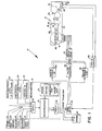
- FIG. 1 An automatic exposure control system 10 incorporating the present invention is shown in block diagram form in Fig. 1.
- System 10 includes a dynamic aperture scanning shutter blade mechanism 12 which is configured to be driven by a reversible stepper motor 14 operated, in a closed loop manner by a stepper motor drive circuit 16 (and later-to-be- described position feedback control loop and drive mode selection system) under the control of a microcomputer 18.
- the operation of a microcomputer 18 is, in turn, responsive to a plurality of inputs.
- cycle start input 19 provided in response to the operator manually actuating an exposure cycle start button and automatically provided inputs such as a pre-exposure scene ambient brightness level, designated 20, an image brightness level at the film plane, measured during the course of an exposure interval, designated 22, and a camera-to-scene distance input, designated 23, which is preferably provided by a sonar ranging and lens focusing system which may be of the type disclosed in U. S. Patent No. 4,081,626.
- Additional inputs may be provided manually by the operator.
- the operator may set a four-position switch 24 to select a normal or balanced mode 26, a depth-of-field emphasizing mode 28, a motion stopping emphasizing mode 30, or a strobe flash mode 31. If the strobe unit is not permanently attached to the system, switching to the flash mode may take place automatically in response to operatively connecting the strobe unit.
- the microcomputer 18 utilizes a trajectory program appropriate for general ambient light photography whereby blade mechanism 12-is operated in a manner that is balanced or optimized for the best compromise between depth of field and motion stopping ability.
- the selection of either the depth of field or stop motion modes overrides the provision of the general photography program and substitutes therefor appropriate trajectory programs which emphasize the selected characteristics, i.e., effective aperture or exposure interval.
- the computer 18 utilizes a flash mode trajectory program and a strobe operating data base for selecting strobe operating parameters such as strobe firing aperture and quench time.
- the exposure control system 10 is intended for use in photographic apparatus, such as a camera C or the like, for controlling the transmission of image forming light rays of a scene 32 provided by objective lens 34 to a film unit 36 located at the camera's film plane 38.
- System 10 also includes an illumination measuring network 40 which utilizes a first photocell 42 mounted on the camera to receive the light from a selected portion of the field of view of lens 34 and providing the pre-exposure scene brightness level input 20 and a second photocell 44 mounted on the interior of the camera for receiving light from the image formed at the film plane on a film unit 36 for providing input 22 to the microcomputer 18.
- a measure of scene brightness may be obtained by using a single photocell directed toward the scene through appropriate aperture shapes associated with the blade mechanism to provide both the pre-exposure input 20 and then the input 22 during the course of the exposure interval.
- the camera-to-scene distance input 23 is provided by a sonar ranging and focusing system 45.
- a variable output electronic strobe unit 47 for providing a source of artificial illumination directed toward the scene 32.
- the light output of strobe unit 47 may be varied between minimum and maximum values by adjusting the interval between strobe firing and quenching signals.
- the term “brightness” or “brightness level” is intended to mean the illumination level of the scene or image at the film plane as it is commonly measured in the photographic art for determining proper film exposure value.
- blade mechanism 12 is of the integrated type that performs both the effective aperture and exposure interval defining functions.
- blade mechanism 12 comprises a pair of thin, elongated blade members 46 and 48 mounted by means (not shown) in superposed relation for simultaneous reciprocal displacement in opposite directions, in response to rotation of stepper motor 14, between positions blocking and unblocking the transmission of image forming light to the film plane 38.
- the forwardmost blade member 46 includes a generally rectangular major section 50 having a longitudinally tapered opening 52 therein; and an integrally formed elongated drive arm 54 extending laterally (to the left) from the lower left-hand end of major section 50 and including on the upper horizontal edge thereof an integrally formed toothed rack 56 that is in mesh with the underside of a drive pinion 58 fixedly secured to the drive shaft 60 of stepper motor 14.
- the rear blade 48 includes a major section 62 having a complementary tapered opening 64 therein; and an integrally formed' upper drive arm 66 having a toothed rack 68 on its lower horizontal edge in mesh with the top side of drive pinion 58.
- gear 58 will drive forward blade member 46 to the right and simultaneously drive rear blade member 48 to the left so that openings 52 and 64 will be completely out of registration with their narrow tapered ends in facing relation to define the closed or light-blocking position of blade mechanism 12.
- gear 58 will drive forward blade member 46 to the right and simultaneously drive rear blade member 48 to the left so that openings 52 and 64 will be completely out of registration with their narrow tapered ends in facing relation to define the closed or light-blocking position of blade mechanism 12.
- the blades are driven in the opposite directions so that openings 52 and 64 progressively overlap and cooperate to define an exposure aperture 70 that is centered on the optical axis of objective lens 34.
- exposure aperture 70 becomes progressively larger until it defines a maximum obtainable aperture wherein the major portions of openings 52 and 64 are in full registration.
- exposure aperture 70 progressively decreases in size until it closes.
- the change in size of the exposure aperture 70 with each incremental step of the blade mechanism 12 will, of course, depend on the selected shape for the openings 52 and 64. It should be understood that it is within the scope of the present invention to use openings 52 and 64 that provide uither linear or nonlinear rates of changes in exposure aperture size as a function of blade displacement and that the particular shape of the openings 52 and 64 shown in Fig. 1 are by way of illustration only.
- the operation of blade mechanism 12 and the nature of the resultant exposure may be characterized by an aperture size or area (Y-axis) versus exposure time or interval (X-axis) trajectory curve.
- the area under the trajectory curve is indicative of the total quantity of ambient image light of known intensity that impinges upon the film unit.
- the shape of the curve defines the average or effective aperture and exposure interval and is therefore indicative of depth of field and motion stopping ability.
- the versatility of a scanning shutter mechanism can be rated on its ability, or lack thereof, to generate a variety of different trajectory curves utilizing the largest possible portion of the plotting area.
- mechanical shutters and their drive systems inherently have mass and inertial characteristics that preclude instantaeous blade movement from a closed position to a predetermined aperture.
- a blade mechanism that can be driven in a controlled manner at a relatively fast maximum rate will be more versatile than a shutter that has a lower rate limit.
- trajectory curve A is triangular in shape and indicates that the aperture increases at a fixed rate to a peak-aperture and then decreases at the sane rate until the shutter closes. Because the rate of blade displacement is fixed, the slope of the opening and closing portions of the trajectory cannot be changed. If exposure interval is increased, the size of the peak aperture increases accordingly.
- the trajectory shape can be changed somewhat, however, by stopping blade displacement at a given peak aperture for a given time before closing so that the trajectory has a truncated shape. Versatility is still quite low because the trajectories are constrained to a family of curves that have fixed slopes in their opening and closing sections.
- the performance versatility of blade mechanism 12 can be increased substantially by providing a drive system wherein the rate at which stepper motor 14 is driven can be changed. For example, to photograph a very bright scene, it may be desirable to open the blades slowly (shallow slope) to a relatively small peak aperture and then close the blades at the same rate. The high brightness level will keep the exposure interval short (good motion stopping ability) while the relatively small effective aperture will insure good depth of field.
- the blade mechanism 12 should be driven at a faster rate so that it reaches larger peak and effective apertures during the course of the exposure.interval.
- a variable drive rate shutter will also allow a choice of trajectory curve shapes to emphasize different exposure parameters. Obviously, then, a shutter in which the rate of blade displacement can be changed for different exposures has increased versatility.
- trajectory curves are no longer limited to having linear opening and closing portions and versatility is once again increased.
- curve B shows a generally triangular trajectory that has sagging or approximately parabolic sides and under current thinking tends to be the best balanced compromise between depth of field and motor stopping.
- the blade mechanism opens to the maximum aperture and then closes in the same manner so that the closing section of the trajectory is a mirror image to the opening section.
- Trajectory C is indicative of an exposure where the blades open at a much faster rate to the maximum aperture where it is maintained for a .period of time before it closes.
- Trajectory D indicates that the blades open at some intermediate rate to a peak aperture, well below maximum aperture, where it is held for a period of time before it is closed.
- the motor drive system can operate at different rates, and provide blade acceleration and deceleration during exposure, then the scanning shutter system will be highly versatile in that a greater number of different shaped trajectories may be generated to best accommodate a variety of photographic situations.
- a stepper motor drive system was chosen for exposure control system 10 because it can be accelerated and decelerated in a controlled manner during the course of a typical exposure interval to generate a large number of different trajectory curve shapes and it is also compact and relatively inexpensive considering its intended function.
- a stepper motor suitable for use in exposure control system 10 typically has a permanent magnet rotor with four coil unipolar or bifilar windings.
- the blades 46 and 48 are typically displaced (1.27cm) one-half inch/between the closed and maximum aperture defining positions.
- a 24-step/revolution motor (15°/step) may be operated in a half-step mode (48-steps/revolution) and drive the blades 46 and 48 between the closed and maximum aperture defining position with 180° rotation, i.e., 24 steps (7.5°/step).
- the holding torque-to-inertia (rotor plus load) ratio should be as large as possible.
- motor 14 may be operated in the half step mode simply by changing the pattern of coiled energization so that on an alternating basis, either one or two coils at a time are energized to effect stepping.
- the stepper motor drive circuit 16 is responsive to pulse inputs (direction of rotation at terminal D and stepping sequence at terminal S) for effecting the correct sequence of coil energizations to control the rate and direction of motor drive.
- pulse inputs direction of rotation at terminal D and stepping sequence at terminal S
- Such drive circuits are well known in the art and need not be described further here to understand the present invention.
- Trajectory input from microcomputer 18 comprises a program of trajectory signals for controlling the rate and direction of rotation of motor 14 so that blade mechanism 12 operates in a manner characterized by a corresponding trajectory curve.
- the trajectory program includes appropriate clockwise and counterclockwise rotation signals that are ultimately fed to terminal D of circuit 16 and a series of motor stepping pulse signals which are fed to terminal S for controlling the angular relation between the rotor and stator magnetic fields to effect operation of stepper motor 14.
- the microcomputer 18 comprises an input device or buffer 72 for feeding the previously noted inputs in appropriately encoded form to a microprocessor or central processing unit 74.
- Microprocessor 74 interacts with a preprogrammed read only memory (ROM) 76 which has separate sections for storing the control program defining the computer's operating instructions; a trajectory data base which microprocessor 74 will utilize to develop a plurality of different trajectory signal programs, appropriate for both ambient light and strobe flash operation, in response to the different inputs; and a strobe operating data base which will be used in conjunction with scene brightness level and range inputs to select an appropriate strobe firing aperture and quench time.
- ROM read only memory
- the output from microprocessor 74 is fed through an output device or buffer 78 to the motor drive system and strobe unit 47.
- stepper motor 14 could be driven in an open loop manner, the performance level of the system is somewhat enhanced by adding a position feedback control loop.
- This control loop includes a blade displacement encoder system 80 for monitoring the stepwise position of blade member 46 during the course of an exposure interval; a logic and counter network 82 for receiving pulse signals from encoder system 80 and providing a displacement output signal indicative of the stepwise position of blade member 46 7 and a mode select network 84 for receiving and comparing the input trajectory signal with the displacement signal and providing to stepper motor drive circuit 16 either a follow trajectory input 86 comprising the original input trajectory signal from microcomputer 18 when the blade member 46 is in the correct position for the planned trajectory or, when there is a large enough variance between the displacement output and the trajectory output, a corrective signal program which switches the stepper motor to a maximum torque mode of operation via the provision of either maximum torque-clockwise or maximum torque-counterclockwise input, designated 88 and 89 respectively.
- the encoder system 80 is an optical two quadrature track encoder that senses the position of blade member.46 throughout the exposure interval.
- the encoder system comprises a longitudinally extending array of vertical slits 90 in blade member 46, a pair of light emitting diodes (LEDs) 94 and 96 (see Fig. 2) positioned behind slits 90 and a corresponding pair of aligned photosensitive detectors or photocells 98 and 100 located on the forward side of the blade member 46 in front of slits 90 and in alignment with the LEDs.
- LEDs light emitting diodes
- the slits 90 and the intervening opaque segments In response to movement of blade member 46, the slits 90 and the intervening opaque segments.therebetween sequentially unblock and block transmission of light from the LEDs to the corresponding photocell detectors 98 and 100 to produce a digitally encoded output therefrom in a well-known manner.
- the outputs from detectors 98 and 100 are fed to network 82 which includes a logic circuit for decoding directional information and a counter for counting each step of blade displacement.
- the count is set at 0 when the blades are at the initial position several steps beyond the closed position to insure the apertures are fully out of registration for light sealing purposes and the count increases as the blades move in the opening direction and decreases in response to a directional change signal when the blades reverse direction.
- the mode select network 84 is a logic subsystem which compares the blade displacement output or count from network 82 with the directional and stepping pulse input trajectory signals (D and S) provided by microcomputer 18. If there is correlation, indicating that the blade member 46 is in the correct position to follow the planned trajectory, then network 84 operates in its normal follow trajectory mode (input 86) and continues to supply the original trajectory signal program from microcomputer 18 to the stepper motor drive circuit 16. However, if the signal comparison indicates that blade member 46 is either ahead of or is lagging behind the correct position too much, network 84 automatically switches to a maximum torque mode of operation and provides a corrective signal program to operate the stepper motor drive circuit 16 in a maximum torque mode.
- the corrective signal program comprises the provision of appropriate maximum torque directional and stepping pulse inputs 88 or 89 to either accelerate or decelerate motor 14 and thereby move the blade mechanism 12 toward the correct position. Such corrective action will continue until the feedback count from network 82 indicates that the blade mechanism 12 is at its correct position to generate the planned trajectory at which point network 84 automatically switches back to the follow trajectory mode resuming the provision of input 86.
- microcomputer 18 In Fig. 1, the major components of microcomputer 18 are shown separately merely to identify their functions. In its actual construction, microcomputer 18 may be formed on a single substrate (computer on a chip) or may comprise a plurality of appropriately interconnected separate large scale integrated circuits.
- microcomputer 18 to define and control the operation of the blade mechanism 12 and the strobe unit 47 in response to one or more inputs provides a great deal of flexibility in how the exposure control system may be used because selection of the operating characteristics of these components now simply becomes a matter of programming microcomputer 18.
- the addition of the flash mode capability to the exposure control system may be achieved at relatively low cost in that it can be readily accomplished by using a moderately upgraded version of the microcomputer that is used in the exposure control system used in the previously-noted specification.
- computer 18 may be programmed in a more detailed manner to be responsive to additional inputs including those relating to film speed or other characteristics for providing a greater number of different trajectory signal programs. More importantly, perhaps, exposure control system can be periodically updated at the factory by reprogramming microcomputer 18 to take advantage of new ideas in exposure control.
- system 10 functions in the ambient mode when the scene is illuminated by natural light
- the system is configured as shown in Figs. 1 and 2 with the mode selection switch 24 in the balanced position to provide input 26.
- illumination measuring circuit 40 and its associated photocell 42 are energized to provide a pre-exposure scene brightness level input 20.
- the sonar ranging system 45 automatically operates at the same time providing a distance measurement input and setting the lens 34 in the correct focus position. The distance input is not utilized for ambient mode operation.
- blade mechanism 12 Based on the scene brightness level 20, the characteristics or speed of the film used, and the properties of the camera's optical system, it has been determined that proper exposure, balanced for depth of field and motion stopping ability, will be obtained if blade mechanism 12 is operated in a manner characterized by the trajectory curve F shown in Fig. 4.
- the opening portion, FO is approximately parabolic,. showing that the rate of change of aperture area starts out slowly and then progressively accelerates until a peak aperture, less than the maximum obtainable aperture, is defined at which point the direction of stepper motor drive is reversed to define the closing section, FC, which is essentially a mirror image of the opening section, FO.
- FC which is essentially a mirror image of the opening section, FO.
- the symmetrical nature of F indicates that 50% of the total exposure light impinges upon the film unit 36 during the opening phase and the other 50% during the closing phase. That is, the blades are reversed at 50% of the total desired exposure.
- the trajectory data base section of ROM includes data serving at least as characterizing elements of a plurality of different shaped curves.
- data for a family of balanced trajectory curves which will vary in the shape of their opening and closing sections for different scene brightness levels.
- the opening and closing slopes will be relatively shallow so that both the peak and average or effective aperture will be relatively small.
- the opening and closing slopes will be steeper indicating that the blades will open more rapidly to a higher peak and effective aperture for a similar exposure interval to produce the same exposure value.
- there will be additional data in the trajectory data base defining separate families of trajectories appropriate for depth of field and motion stopping ability emphasizing ambient modes and for the strobe flash mode.
- the microprocessor 74 In response to the various inputs, in this case balanced mode input 26 and scene brightness level input 20, the microprocessor 74, operating under the control of the instructional program and ROM 76, will select appropriate data from the balanced family of trajectories and develop therefrom a program of trajectory signals that will cause the stepper motor 14 to drive blade mechanism 12 in a manner characterized by the trajectory curve F.
- the trajectory data base of ROM 76 could be programmed with enough data to define the entire curve F based on the pre-exposure input 20 alone. However, in a preferred embodiment it is programmed only to include data defining the shape of the opening portion of each of the plurality of trajectories for the reasons of programming economy and added flexibility. Additionally, the closed loop on the photocell reduces effects of parameter variations.
- Microcomputer 18 initially provides the appropriate program of trajectory signals to effect the driving of blade mechanism 12 from its closed position toward its fully open position along trajectory portion FO.
- the illumination measuring circuit 40 and photocell 44 operate in a light integrating mode to monitor the image illumination level at the film plane and provide input 22.
- the microprocessor 74 changes the program of trajectory signals to reverse the blade drive.
- the mirror image closing portion FC of the trajectory curve F is generated by reversing the opening trajectory signal program utilized up to the turn around point. That is, a record of the opening section of the trajectory signals is maintained in storage and then is utilized to define the mirror image closing portion of the trajectory.
- selector switch 24 If the operator wishes to emphasize depth of field or motion stopping ability, he merely changes the setting of selector switch 24 to provide either input 28 or 30. These inputs override selection from the balanced trajectory data and switch selection to the appropriate alternative program.
- microcomputer 18 By appropriately programming microcomputer 18 to vary the rate of blade mechanism displacement, including acceleration or deceleration, during the course of an exposure interval, a wide variety of characterizing trajectory curves may be generated. These may have linear or nonlinear portions, or combinations of both. Also, they may be symmetrical or asymmetrical.
- the dynamic response of exposure control system 10 is a major determining factor as to whether or not it can accurately generate a particular trajectory curve characterizing the operation of the blade mechanism 12. More accurate dynamic response is, of course, enhanced significantly by utilization of the positional feedback control loop and mode select system described earlier.
- the strobe flash subsystem of exposure control system 10 automatically selects a strobe firing aperture and adjusts the light output of quenchable strobe unit 47 in response to scene brightness and distance inputs for providing the desired amount of artificial illumination contribution to exposure value.
- the strobe contribution is relatively high.
- ambient and flash illumination are mixed in a controlled manner so that the strobe unit primarily serves to provide a proportional fill flash capability.
- the flash subsystem is configured to be compatible with and enhance the versatility of those aspects of the exposure control system 10 described up to this point.
- the cost of adding the flash capability is relatively low in that it only requires the addition of a strobe unit connector and a modest expansion of the microcomputer's memory section to accommodate the strobe operation data base and the additional control program for coordinating the firing and quenching of unit 47 with the operation of blade mechanism 12.
- new flash techniques can be explored simply by reprogramming .
- Another advantage is that it is possible to make small programming adjustments to "fine tune" the exposure control system to take advantage of selected exposure characteristics of the film and/or to compensate for the dynamic response characteristics of other components in the system. Also, as flash techniques improve in the future, these advances may be incorporated into new camera models by reprogramming at the factory.
- the position feedback control loop provides accurate tracking of the trajectory curve and allows the strobe to be fired and quenched at selected points along that curve with great precision.
- the exposure control system embodying the present invention exploits variation of both aperture and strobe output as functions of scene brightness and camera-to-scene distance in its operating scheme. In doing this in conjunction with tailoring the trajectories for flash mode operation, the effective range of the strobe unit is significantly expanded for both close and far camera-to-subject distances.
- FIG. 5 A somewhat idealized strobe flash mode performance goal for exposure control system 10 is graphically depicted in Fig. 5 wherein exposure value is plotted as a function of normalized exposure (Y-axis) and ambient scene brightness level (X-axis). Total exposure is the sum of the strobe and ambient contributions at any point along the X-axis. The optimum exposure value is normalized at 1.00. The goal is to maintain exposure value at 1.00 from 0 to approximately 575 cd/(sq. ft.) and then linearly increase exposure value from 1.00 to 1.40 in the brightness range from 575 to 800 cd/(sq. ft.).
- Exposure value is increased in this high ambient range to compensate for reciprocity failure of the film and also to slightly overexpose the film for aesthetic reasons, i.e., emphasize the high brightness level of the scene.
- Another characteristic of this flash mode goal is to maintain the ratio of approximately 75% ambient to 25% flash illumination in that portion of the brightness range (above approximately 25 cd/(sq. ft.) for film speed of approximately 150 ASA) wherein the ambient level is high enough to provide 75% of the total utilizing a shutter speed that is acceptable for handheld camera operation.
- the selection of this particular ratio reflects current thinking in the photographic art as to scene lighting techniques that provide aesthetically pleasing photographs.
- the strobe provides 100% of the scene illumination. As ambient brightness increases, the strobe contribution is decreased proportionally to maintain the total exposure at the normalized 1.00 value. At approximately 15 cd/(sq. ft.), there is a crossover (50% ambient plus 50% strobe). When the brightness level reaches approximately 25 cd/(sq. ft.) there is enough ambient light to provide .75% of the total and the strobe output is regulated to supply the remaining 25%. This same ratio is maintained for the increased exposure values in the 575 to 800 cd/(sq. ft.) range. The brightness figures given here will vary with fill speed.
- the strobe is the primary source of scene illumination for effecting film exposure.
- the strobe operates in a fill flash mode to provide supplemental illumination that is directed toward the scene from a direction that is usually different from the direction of the ambient-light to soften or eliminate shadows cast by blockage of portions of the ambient light rays and also to increase the illumination of relatively dark areas of the scene to bring out details thereof and reduce contrast.
- strobe mode plan shown in Fig. 5 is a goal only, and in practice interactive exposure parameters and performance limitations of certain of the components will not allow the goal to be met for various combinations of scene brightnesses and distances.
- the flash mode strategy used in exposure control system 10 is to try and maintain the idealized flash mode goal over the widest range of scene brightness levels and camera-to-subject distances, and, when this is not possible because of strobe output limitations, available aperture limitations or adverse scene lighting conditions, to make adjustments that will provide the best possible photograph consistent with these limitations and conditions.
- the amount of strobe light that reaches the film plane varies as a function of strobe output level, camera-to-scene distance, and effective aperture during the strobe firing interval. If the strobe output level is fixed, then effective aperture must be increased proportionally for increasing camera-to-scene distances to maintain the constant strobe contribution level. Conversely, if effective aperture is held constant, the strobe output level must be adjusted in accordance with scene distance.
- the exposure control system 10 embodying the present invention selectively varies both effective aperture and strobe output level (by varying the timing of the quench signal) to regulate strobe contribution and expand the effective range of unit 47 as will become apparent later.
- trajectory shape is available to contribute to the optimization of flash mode operation. That is, because the shutter can be programmed to generate a wide variety of different trajectory shapes, it is now possible to provide trajectories that are specifically designed to enhance flash mode operation. Unlike prior art systems wherein variation and trajectory shape is not available or is severely limited, trajectory shape can be exploited to advantage rather than being an obstacle that has to be worked around.
- Fig. 6 shows a typical trajectory curve generated by system 10 for fill flash operation.
- the integrated area under the curve is indicative of the ambient light contribution, which in this case is set to provide 75% of the total required exposure as determined by the pre-exposure scene brightness input. The remaining 25% will be supplied by the strobe unit 47.
- the instantaneous aperture defined by the blade mechanism 12 is represented by an encoder count or step number.
- 5 m is the designated peak aperture, in this example f 8.16, and corresponds to an encoder count 5 52 .
- S m is inten- tionally selected to occur slightly past the peak of the trajectory on the closing portion thereof. This is done to improve control because there may be some slight variation of the exact blade reversal point. That is, S m is chosen to occur at the largest aperture where blade position is very accurately defined and the blade drive system is more stabilized than at the turnaround portion at the absolute top of the trajectory.
- a strobe firing aperture, S, and a quench time, Q are selected by microcomputer 18 in a manner to be set forth in detail later.
- the blade mechanism 12 is driven in accordance with the developed trajectory signal program to define the opening slope.
- the program provides a signal to reverse the direction of stepper motor drive.
- the stepper motor decelerates and reverses direction in a manner to define the central peak portion of a trajectory.
- the strobe unit 47 is fired at the selected strobe firing aperture by the provision of a firing signal, F s , and continues to emit light until it is quenched by the provision of quench signal Q.
- the amount of strobe contribution can be varied in two ways. First, by choosing aperture size and, secondly, by varying strobe output between minimum and maximum output levels in response to adjusting the interval between the firing signal, F s , and the quench signal, Q.
- the selection of the appropriate strobe firing aperture S and the corresponding quench time, Q, is performed automatically by microcomputer 18 utilizing the pre-exposure scene brightness and camera-to-scene distance inputs, b and d respectively, the preprogrammed strobe operation data base, and a control program for manipulating the data.
- the total camera-to-scene distance range is divided into four (4) sequential zones designated Dl, D2, D3 and D4.
- D1 covers scene distance of approximately 1 to 3 ft. (1/3-1 metre); D2, 3-9ft (1-3 metres); D3, 9-27ft. (3-8metres); and D4, 27-35ft. (8-10 metres).
- each of the zones D is subdivided into small increments d.
- the increments d in zone Dl are designated d 1 to d 22 ; D2, d 23 to d 44 ; D3, d 45 to d 66 ; and D4, d 67 to d 72 .
- d 72 is used for the furthest designated distance in zone D4 and all distances therebeyond which are beyond the effective flash range.
- computer 18 correlates with the data in Table 2 and assigns a temporary quench time, Q t .
- the particular zone D in which the scene is located will determine the selection of the strobe firing aperture. That is, in general, the aperture selected for D3 will be larger than the corresponding apertures for either of zones D2 or Dl, but smaller than that selected for zone D4.
- the strobe output is varied in proportion to the distance of the scene from the near end of the designated zone D. That is, when the scene is at the near end of the zone D, the strobe output is at a minimum (Q l ).
- the strobe output is proportionally increased so that Q 22 is used for the last location d in that zone D.
- each zone is "covered” by modulating strobe output.
- the aperture is increased to provide more light input to the film plane and that zone is covered by predetermined modulation of the strobe output.
- the init-ial selection of Q t is temporary, however, because it is based solely on camera-to-scene distance before consideration of the brightness level b. That is, the initially selected Q t will be appropriate if the corresponding strobe firing aperture determined by D is smaller than 5m using the trajectory curve for 75% ambient contribution selected in accordance with the brightness level b. For example, if the S m (designated peak aperture) for a given brightness level b is larger than the selected strobe firing aperture, then the initial selected Q t may be used to achieve the desired ambient-to-strobe contribution level.
- the strobe logic system will attempt to adjust (increase) the Q t by an appropriate increment to compensate for the aperture limitation to maintain the contribution ratio. If the required increment exceeds the maximum output, then the system will automatically fire the strobe at the peak aperture with maximum output (Q 22 ) to achieve the best possible exposure even though the target ratio of 75% ambient to 25% strobe cannot be maintained under these scene brightness and distance conditions.
- microcomputer 13 consults a matrix table in the strobe operation data base to compare S m with the selected strobe ficing aperture set forth therein as S (encoder step numbers).
- This matrix Table 3 is shown below along with Table 4 that may be used to convert encoder step number S to the corresponding f number. Note that in Table 4 encoder steps So to S 6 correspond to the fully closed blade positions where the apertures 52 and 64 are completely out of registration to provide a good light seal. Thus the number of these positions is infinity.
- Table 3 D selects the column for strobe firing aperture and scene brightness selects the row.
- the strobe provides an output of 452 BCPS rather than the initially selected 367 BCPS to compensate for the limitation in aperture size imposed by the trajectory selected for this higher brightness level to provide the ambient component of the exposure.
- Fig. 7 shows an ambient mode trajectory A and a flash mode trajectory B provided by microcomputer 18 in response to the same level of ambient brightness and scene distance. It will be noted that the flash mode trajectory has steeper slopes .in the opening and closing portion and reaches a higher peak aperture S m to provide more head room for the strobe component. Some depth of field is given up, but-it is more important to extend the range of flash coverage.
- the effective range of the flash unit is extended by a combination of techniques.
- trajectories are specially shaped for flash mode operation to provide larger peak apertures.
- modulation of the strobe extends the range outwardly at the far end and inwardly at the close end. That is, for near scene distances the combination of small aperture and minimum strobe output will allow picture to be taken at closer distances without flash burnout than if the output level of the strobe unit is fixed. At longer scene distances a modulation of the strobe allows range extension when aperture size may be limited.
- the strobe flash method set forth above is only but one of many different ways exposure control system 10 may be programmed for flash photography. Therefore, the method should be considered in its different aspects. First, it provides a way for extending the effective. range of a quenchable strobe unit. Secondly, and perhaps more importantly, it serves to illustrate the versatility of exposure control system 10 and how easily it may be adapted by reprogramming to explore and exploit new flash methods.
Landscapes
- Physics & Mathematics (AREA)
- General Physics & Mathematics (AREA)
- Exposure Control For Cameras (AREA)
- Stroboscope Apparatuses (AREA)
Applications Claiming Priority (2)
| Application Number | Priority Date | Filing Date | Title |
|---|---|---|---|
| US06/275,718 US4354748A (en) | 1981-06-22 | 1981-06-22 | Photographic exposure system with computer controlled strobe unit |
| US275718 | 1988-11-23 |
Publications (2)
| Publication Number | Publication Date |
|---|---|
| EP0068779A1 true EP0068779A1 (fr) | 1983-01-05 |
| EP0068779B1 EP0068779B1 (fr) | 1985-10-30 |
Family
ID=23053523
Family Applications (1)
| Application Number | Title | Priority Date | Filing Date |
|---|---|---|---|
| EP82303221A Expired EP0068779B1 (fr) | 1981-06-22 | 1982-06-21 | Appareil photographique et système de contrôle d'exposition |
Country Status (5)
| Country | Link |
|---|---|
| US (1) | US4354748A (fr) |
| EP (1) | EP0068779B1 (fr) |
| JP (1) | JPS57212422A (fr) |
| CA (1) | CA1174095A (fr) |
| DE (1) | DE3267142D1 (fr) |
Cited By (2)
| Publication number | Priority date | Publication date | Assignee | Title |
|---|---|---|---|---|
| EP0075747B1 (fr) * | 1981-09-25 | 1987-01-14 | Polaroid Corporation | Système et méthode de contrôle de l'exposition photographique par micro-ordinateur |
| EP0271083A3 (en) * | 1986-12-09 | 1989-07-12 | Asahi Kogaku Kogyo Kabushiki Kaisha | Interchangeable flash device |
Families Citing this family (36)
| Publication number | Priority date | Publication date | Assignee | Title |
|---|---|---|---|---|
| US4751543A (en) * | 1983-12-01 | 1988-06-14 | Canon Kabushiki Kaisha | Control signal generator for camera |
| GB2155649B (en) * | 1984-02-06 | 1988-11-09 | Konishiroku Photo Ind | Camera |
| JPS6190138A (ja) * | 1984-10-09 | 1986-05-08 | Konishiroku Photo Ind Co Ltd | 閃光撮影用露出制御装置 |
| JPH0754391B2 (ja) * | 1984-02-14 | 1995-06-07 | オリンパス光学工業株式会社 | カメラの露出制御装置 |
| JPH0625838B2 (ja) * | 1984-03-01 | 1994-04-06 | 株式会社精工舎 | ストロボ制御回路 |
| JPH0625837B2 (ja) * | 1984-05-09 | 1994-04-06 | 株式会社精工舎 | カメラ用シヤツタ |
| US4771309A (en) * | 1985-03-04 | 1988-09-13 | Seikosha Co., Ltd. | Strobe control circuit for flash photography |
| US5134435A (en) * | 1985-04-25 | 1992-07-28 | Canon Kabushiki Kaisha | Camera |
| US4780735A (en) * | 1985-08-29 | 1988-10-25 | Minolta Camera Kabushiki Kaisha | Photographic camera |
| US4754296A (en) * | 1985-11-21 | 1988-06-28 | Polaroid Corporation | Method of and apparatus for displaying alphanumeric range in camera viewfinder |
| JPH0789190B2 (ja) * | 1986-02-03 | 1995-09-27 | キヤノン株式会社 | 自動露出制御装置 |
| US4769667A (en) * | 1986-07-04 | 1988-09-06 | Fuji Photo Film Co., Ltd. | Shutter control apparatus for a camera |
| JPH0524896Y2 (fr) * | 1986-12-26 | 1993-06-24 | ||
| US4878077A (en) * | 1987-09-29 | 1989-10-31 | Olympus Optical Company Ltd. | Motor drive and control apparatus for a camera |
| US4779118A (en) * | 1987-12-07 | 1988-10-18 | Polaroid Corporation | Exposure control with fixed time exposure at high light levels |
| US4785323A (en) * | 1987-12-28 | 1988-11-15 | Eastman Kodak Company | Exposure control |
| JP2529345B2 (ja) * | 1988-04-01 | 1996-08-28 | 富士写真フイルム株式会社 | プログラムシャッタ駆動装置 |
| US5319413A (en) * | 1988-05-16 | 1994-06-07 | Minolta Camera Kabushiki Kaisha | Camera system |
| JPH02105121A (ja) * | 1988-10-14 | 1990-04-17 | Olympus Optical Co Ltd | 絞り制御装置 |
| JPH0283531U (fr) * | 1988-12-16 | 1990-06-28 | ||
| JPH02188730A (ja) * | 1989-01-18 | 1990-07-24 | Fuji Photo Film Co Ltd | カメラの制御装置 |
| JPH0358040A (ja) * | 1989-07-27 | 1991-03-13 | Canon Inc | カメラのストロボ撮影制御装置 |
| JP2512080Y2 (ja) * | 1989-10-09 | 1996-09-25 | 株式会社リコー | テレビモ―ドを持つカメラ |
| JP2775012B2 (ja) * | 1989-10-18 | 1998-07-09 | チノン株式会社 | カメラズームレンズ自動変倍装置 |
| US5014082A (en) * | 1989-12-04 | 1991-05-07 | Polaroid Corporation | Method and apparatus for compensating for shutter speed variations |
| US4978991A (en) * | 1989-12-29 | 1990-12-18 | Polaroid Corporation | Open-loop stepper motor controlled shutter |
| JP2952606B2 (ja) * | 1990-06-21 | 1999-09-27 | セイコープレシジョン株式会社 | カメラ用シヤッタ |
| JP2517472Y2 (ja) * | 1990-06-25 | 1996-11-20 | セイコープレシジョン株式会社 | カメラ用シャッタ |
| JPH04270327A (ja) * | 1991-02-26 | 1992-09-25 | Fuji Photo Optical Co Ltd | カメラの露出補正装置 |
| KR940010591B1 (ko) * | 1991-11-28 | 1994-10-24 | 삼성전자 주식회사 | 자동노출장치 |
| US5335041A (en) * | 1993-09-13 | 1994-08-02 | Eastman Kodak Company | Exposure and focus system for a zoom camera |
| US5678105A (en) * | 1995-12-21 | 1997-10-14 | Polaroid Corporation | Camera shutter and focus lens assembly |
| US5701525A (en) * | 1995-12-21 | 1997-12-23 | Polaroid Corporation | Camera encoder assembly, system and method thereof |
| US7978260B2 (en) * | 2003-09-15 | 2011-07-12 | Senshin Capital, Llc | Electronic camera and method with fill flash function |
| US20150142409A1 (en) * | 2013-11-21 | 2015-05-21 | International Business Machines Corporation | Photographic setup modeling |
| US9218667B2 (en) | 2013-11-25 | 2015-12-22 | International Business Machines Corporation | Spherical lighting device with backlighting coronal ring |
Citations (7)
| Publication number | Priority date | Publication date | Assignee | Title |
|---|---|---|---|---|
| US3733991A (en) * | 1969-06-03 | 1973-05-22 | Minolta Camera Kk | Lens shutter |
| US3836920A (en) * | 1972-02-16 | 1974-09-17 | Canon Kk | Exposure control system for flash photography |
| US3928859A (en) * | 1974-03-22 | 1975-12-23 | Honeywell Inc | Shutter-iris for automatic camera |
| US4047187A (en) * | 1974-04-01 | 1977-09-06 | Canon Kabushiki Kaisha | System for exposure measurement and/or focus detection by means of image senser |
| US4187019A (en) * | 1974-10-29 | 1980-02-05 | Canon Kabushiki Kaisha | Flash light photographic systems |
| US4227808A (en) * | 1977-12-29 | 1980-10-14 | Minolta Camera Kabushiki Kaisha | Digital light measuring device |
| US4243309A (en) * | 1979-03-05 | 1981-01-06 | Polaroid Corporation | Walking beam latch and lens disc actuator arrangement |
Family Cites Families (17)
| Publication number | Priority date | Publication date | Assignee | Title |
|---|---|---|---|---|
| US3710701A (en) * | 1970-12-21 | 1973-01-16 | Canon Kk | Flash device for a camera and a photographing system with an artificial illuminator |
| FR2125289B1 (fr) * | 1971-02-12 | 1975-03-21 | Asahi Optical Co Ltd | |
| US3738242A (en) * | 1971-06-11 | 1973-06-12 | B Lee | Adaptive illumination source intensity control device |
| JPS4930034A (fr) * | 1972-07-17 | 1974-03-18 | ||
| US4005444A (en) * | 1972-09-25 | 1977-01-25 | Canon Kabushiki Kaisha | Exposure control system for flash photography |
| US3917395A (en) | 1973-06-28 | 1975-11-04 | Honeywell Inc | Control circuit for photographic apparatus |
| JPS50115822A (fr) * | 1974-02-22 | 1975-09-10 | ||
| JPS50137536A (fr) * | 1974-04-18 | 1975-10-31 | ||
| GB1508452A (en) * | 1974-04-18 | 1978-04-26 | West Electric Co | Optical control systems |
| JPS5333065B2 (fr) * | 1974-05-30 | 1978-09-12 | ||
| US4035814A (en) * | 1974-09-02 | 1977-07-12 | Asahi Kogaku Kogyo Kabushiki Kaisha | Electronic flash apparatus controlled by a digital memory system |
| JPS5454029A (en) * | 1977-10-06 | 1979-04-27 | Canon Inc | Light varying strobo camera of program type |
| US4236794A (en) * | 1979-03-05 | 1980-12-02 | Gordon Gary B | Self-focusing camera apparatus and method |
| US4297012A (en) * | 1978-12-13 | 1981-10-27 | Minolta Camera Kabushiki Kaisha | Exposure control arrangement for photographic cameras |
| US4297011A (en) * | 1979-05-10 | 1981-10-27 | Rollei Of America, Inc. | Photoflash device |
| US4317624A (en) * | 1980-11-03 | 1982-03-02 | Polaroid Corporation | Strobe camera having range correlated scanning blade endoding |
| US4325614A (en) * | 1980-12-16 | 1982-04-20 | Polaroid Corporation | Exposure control system with shutter operation controlled by a microcomputer |
-
1981
- 1981-06-22 US US06/275,718 patent/US4354748A/en not_active Expired - Lifetime
-
1982
- 1982-05-13 JP JP57080833A patent/JPS57212422A/ja active Granted
- 1982-06-17 CA CA000405442A patent/CA1174095A/fr not_active Expired
- 1982-06-21 EP EP82303221A patent/EP0068779B1/fr not_active Expired
- 1982-06-21 DE DE8282303221T patent/DE3267142D1/de not_active Expired
Patent Citations (7)
| Publication number | Priority date | Publication date | Assignee | Title |
|---|---|---|---|---|
| US3733991A (en) * | 1969-06-03 | 1973-05-22 | Minolta Camera Kk | Lens shutter |
| US3836920A (en) * | 1972-02-16 | 1974-09-17 | Canon Kk | Exposure control system for flash photography |
| US3928859A (en) * | 1974-03-22 | 1975-12-23 | Honeywell Inc | Shutter-iris for automatic camera |
| US4047187A (en) * | 1974-04-01 | 1977-09-06 | Canon Kabushiki Kaisha | System for exposure measurement and/or focus detection by means of image senser |
| US4187019A (en) * | 1974-10-29 | 1980-02-05 | Canon Kabushiki Kaisha | Flash light photographic systems |
| US4227808A (en) * | 1977-12-29 | 1980-10-14 | Minolta Camera Kabushiki Kaisha | Digital light measuring device |
| US4243309A (en) * | 1979-03-05 | 1981-01-06 | Polaroid Corporation | Walking beam latch and lens disc actuator arrangement |
Cited By (2)
| Publication number | Priority date | Publication date | Assignee | Title |
|---|---|---|---|---|
| EP0075747B1 (fr) * | 1981-09-25 | 1987-01-14 | Polaroid Corporation | Système et méthode de contrôle de l'exposition photographique par micro-ordinateur |
| EP0271083A3 (en) * | 1986-12-09 | 1989-07-12 | Asahi Kogaku Kogyo Kabushiki Kaisha | Interchangeable flash device |
Also Published As
| Publication number | Publication date |
|---|---|
| US4354748A (en) | 1982-10-19 |
| EP0068779B1 (fr) | 1985-10-30 |
| JPS57212422A (en) | 1982-12-27 |
| DE3267142D1 (en) | 1985-12-05 |
| JPH035726B2 (fr) | 1991-01-28 |
| CA1174095A (fr) | 1984-09-11 |
Similar Documents
| Publication | Publication Date | Title |
|---|---|---|
| EP0068779B1 (fr) | Appareil photographique et système de contrôle d'exposition | |
| EP0075747B1 (fr) | Système et méthode de contrôle de l'exposition photographique par micro-ordinateur | |
| JPH0513290B2 (fr) | ||
| US4592638A (en) | Automatic focus adjusting device | |
| US4437744A (en) | Automatic exposure control apparatus for camera | |
| US4518242A (en) | Automatic focus adjusting device | |
| US5126778A (en) | Dedicated photographic flash system for varying flash spread based upon camera-to-subject distance | |
| EP0804752B1 (fr) | Systeme et procede de commande de l'obturateur electronique d'un appareil photo | |
| US5692118A (en) | Autofocus control device having moving body tracking control | |
| US5255047A (en) | Strobo controlling apparatus | |
| US4771309A (en) | Strobe control circuit for flash photography | |
| US4827304A (en) | Camera | |
| US5255049A (en) | Shutter control device for camera and control method therefor | |
| US5404192A (en) | Camera having a rapid picture-taking operation | |
| US4577952A (en) | Photographic camera having a diaphragm actuator with preliminary displacement for lens compensation | |
| US5099267A (en) | Exposure control apparatus of camera | |
| US5113216A (en) | Camera | |
| JP3352236B2 (ja) | シャッター装置 | |
| JPH0222632A (ja) | カメラ | |
| US5253009A (en) | Exposure control apparatus of camera having an auto-exposure bracket mode | |
| US4929977A (en) | Flash photography changeover device | |
| US4550997A (en) | Automatic exposure control circuit | |
| CN100401178C (zh) | 在良好聚焦条件下拍照的照相机 | |
| US5164758A (en) | Exposure control apparatus of camera having an automatic exposure bracket drive mode | |
| US5017956A (en) | Flash photography system |
Legal Events
| Date | Code | Title | Description |
|---|---|---|---|
| PUAI | Public reference made under article 153(3) epc to a published international application that has entered the european phase |
Free format text: ORIGINAL CODE: 0009012 |
|
| AK | Designated contracting states |
Designated state(s): DE FR GB |
|
| 17P | Request for examination filed |
Effective date: 19830307 |
|
| GRAA | (expected) grant |
Free format text: ORIGINAL CODE: 0009210 |
|
| AK | Designated contracting states |
Designated state(s): DE FR GB |
|
| REF | Corresponds to: |
Ref document number: 3267142 Country of ref document: DE Date of ref document: 19851205 |
|
| ET | Fr: translation filed | ||
| PLBE | No opposition filed within time limit |
Free format text: ORIGINAL CODE: 0009261 |
|
| STAA | Information on the status of an ep patent application or granted ep patent |
Free format text: STATUS: NO OPPOSITION FILED WITHIN TIME LIMIT |
|
| 26N | No opposition filed | ||
| PGFP | Annual fee paid to national office [announced via postgrant information from national office to epo] |
Ref country code: FR Payment date: 19980508 Year of fee payment: 17 |
|
| PGFP | Annual fee paid to national office [announced via postgrant information from national office to epo] |
Ref country code: GB Payment date: 19980522 Year of fee payment: 17 |
|
| PGFP | Annual fee paid to national office [announced via postgrant information from national office to epo] |
Ref country code: DE Payment date: 19980528 Year of fee payment: 17 |
|
| PG25 | Lapsed in a contracting state [announced via postgrant information from national office to epo] |
Ref country code: GB Free format text: LAPSE BECAUSE OF NON-PAYMENT OF DUE FEES Effective date: 19990621 |
|
| PG25 | Lapsed in a contracting state [announced via postgrant information from national office to epo] |
Ref country code: FR Free format text: THE PATENT HAS BEEN ANNULLED BY A DECISION OF A NATIONAL AUTHORITY Effective date: 19990630 |
|
| GBPC | Gb: european patent ceased through non-payment of renewal fee |
Effective date: 19990621 |
|
| PG25 | Lapsed in a contracting state [announced via postgrant information from national office to epo] |
Ref country code: DE Free format text: LAPSE BECAUSE OF NON-PAYMENT OF DUE FEES Effective date: 20000503 |
|
| REG | Reference to a national code |
Ref country code: FR Ref legal event code: ST |