EP0069193B1 - Mit einer Membran versehene zusammenklappbare Konstruktion - Google Patents
Mit einer Membran versehene zusammenklappbare Konstruktion Download PDFInfo
- Publication number
- EP0069193B1 EP0069193B1 EP82101836A EP82101836A EP0069193B1 EP 0069193 B1 EP0069193 B1 EP 0069193B1 EP 82101836 A EP82101836 A EP 82101836A EP 82101836 A EP82101836 A EP 82101836A EP 0069193 B1 EP0069193 B1 EP 0069193B1
- Authority
- EP
- European Patent Office
- Prior art keywords
- members
- bolt
- framework
- retaining
- membrane structure
- Prior art date
- Legal status (The legal status is an assumption and is not a legal conclusion. Google has not performed a legal analysis and makes no representation as to the accuracy of the status listed.)
- Expired
Links
- 239000012528 membrane Substances 0.000 title claims description 67
- 238000010276 construction Methods 0.000 claims description 11
- 239000000463 material Substances 0.000 claims description 4
- 238000005452 bending Methods 0.000 description 4
- 238000000034 method Methods 0.000 description 2
- 230000004048 modification Effects 0.000 description 2
- 238000012986 modification Methods 0.000 description 2
- 238000003466 welding Methods 0.000 description 2
- 230000003466 anti-cipated effect Effects 0.000 description 1
- 230000000712 assembly Effects 0.000 description 1
- 238000000429 assembly Methods 0.000 description 1
- 230000001788 irregular Effects 0.000 description 1
- 239000002184 metal Substances 0.000 description 1
- 238000012856 packing Methods 0.000 description 1
- 230000002787 reinforcement Effects 0.000 description 1
Images




Classifications
-
- E—FIXED CONSTRUCTIONS
- E04—BUILDING
- E04H—BUILDINGS OR LIKE STRUCTURES FOR PARTICULAR PURPOSES; SWIMMING OR SPLASH BATHS OR POOLS; MASTS; FENCING; TENTS OR CANOPIES, IN GENERAL
- E04H15/00—Tents or canopies, in general
- E04H15/32—Parts, components, construction details, accessories, interior equipment, specially adapted for tents, e.g. guy-line equipment, skirts, thresholds
- E04H15/64—Tent or canopy cover fastenings
-
- E—FIXED CONSTRUCTIONS
- E04—BUILDING
- E04B—GENERAL BUILDING CONSTRUCTIONS; WALLS, e.g. PARTITIONS; ROOFS; FLOORS; CEILINGS; INSULATION OR OTHER PROTECTION OF BUILDINGS
- E04B1/00—Constructions in general; Structures which are not restricted either to walls, e.g. partitions, or floors or ceilings or roofs
- E04B1/343—Structures characterised by movable, separable, or collapsible parts, e.g. for transport
- E04B1/344—Structures characterised by movable, separable, or collapsible parts, e.g. for transport with hinged parts
- E04B1/3441—Structures characterised by movable, separable, or collapsible parts, e.g. for transport with hinged parts with articulated bar-shaped elements
-
- E—FIXED CONSTRUCTIONS
- E04—BUILDING
- E04B—GENERAL BUILDING CONSTRUCTIONS; WALLS, e.g. PARTITIONS; ROOFS; FLOORS; CEILINGS; INSULATION OR OTHER PROTECTION OF BUILDINGS
- E04B1/00—Constructions in general; Structures which are not restricted either to walls, e.g. partitions, or floors or ceilings or roofs
- E04B1/343—Structures characterised by movable, separable, or collapsible parts, e.g. for transport
- E04B1/3455—Wheeled arch-type structures
-
- E—FIXED CONSTRUCTIONS
- E04—BUILDING
- E04H—BUILDINGS OR LIKE STRUCTURES FOR PARTICULAR PURPOSES; SWIMMING OR SPLASH BATHS OR POOLS; MASTS; FENCING; TENTS OR CANOPIES, IN GENERAL
- E04H15/00—Tents or canopies, in general
- E04H15/32—Parts, components, construction details, accessories, interior equipment, specially adapted for tents, e.g. guy-line equipment, skirts, thresholds
- E04H15/34—Supporting means, e.g. frames
- E04H15/44—Supporting means, e.g. frames collapsible, e.g. breakdown type
- E04H15/48—Supporting means, e.g. frames collapsible, e.g. breakdown type foldable, i.e. having pivoted or hinged means
- E04H15/50—Supporting means, e.g. frames collapsible, e.g. breakdown type foldable, i.e. having pivoted or hinged means lazy-tongs type
- E04H15/505—Supporting means, e.g. frames collapsible, e.g. breakdown type foldable, i.e. having pivoted or hinged means lazy-tongs type characterised by connecting arches with lazy-tongues
Definitions
- the present invention relates to an improvement of a collapsible membrane structure such as a so-called temporary housing structure comprising a multiplicity of frame members connected to one another, the outer surfaces being covered with a membrane covering.
- leg members are arranged to be foldable relative to the roof members in order to reduce the overall dimensions of the structure when it is to be transported, stored, etc.
- either of the rafter members or the leg members are bent to form the juncture portion of the roof and legs and these members are connected to the other members at the straight portions by suitable hinge means for convenience of transportation.
- the radius of curvature of the bend at the position corresponding to the shoulder part of the structure had to be relatively large due to the bending limitation of the material for such frame members.
- connection of the required frame members was provided by bolts and brackets, the brackets being fixed at the outer surfaces of the members to be connected, the connection parts tended to project from the framework surface. Such projections are not desirable for transportation under collapsed condition and may damage the membrane.
- the bolts and/or bands for connection were welded to the required parts of the frame, there were problems in terms of stability, strength and easy damage in addition to such welded portion projections.
- the membrane was secured to the outerside of the frame members by means of cord ortapping screws with liner members in between. Consequently much working time was required for securing the membrane.
- FR-A-1 551 593 discloses a hinge arrangement for a tent structure including a locking lever adapted to cooperate with a pivotably mounted lever.
- a collapsible membrane structure having the features of the first part of claim 1 is characterized by the features of the second part of claim 1.
- the structure of the invention has the required strength and a smooth and small radius for protecting the membrane. Furthermore, since the membrane is in close contact with the outer surface of the shoulder part consideration is given to minimizing the number of projections of the frame structure where the membrane contacts therewith and so as to reduce the packing height, the radius of curvature at the shoulder part, namely the hinge portion has been reduced to the greatest extent possible without sacrificing necessary structural strength, without leaving substantially any clearance between both plates when the leg is erected so that a strong and stable hinge connection may be provided.
- connection members are attached by welding or the like and extend therefrom and these connection members serve to join the rafter members or beam members to the leg members through the main body of the shoulder part, i.e. connection blocks, the respective extended connection members being fit into the rafter members, beam members and the leg members respectively.
- the shoulder part serves to provide a compact but strong frame structure.
- novel collapsible membrane structure may be made still more compact in size and easy to collapse, yet having sufficient strength with additional use of the features of claim 2. Additional preferred embodiments of the invention are claimed in claims 3 to 6.
- Retaining members are used as a means to connect the required auxiliary members or the like to the framework.
- the retaining members are fixed beforehand to the required frame members at such location as will come inwardly or laterally when they are installed in the framework except for the portions necessary to be facing outwardly such as for securing the membrane. Accordingly, when the membrane structure is collapsed, the possibility of attaching part projecting outwardly may be reduced while the auxiliary members may be firmly attached.
- the retaining member is formed in channel configuration in section or, as required, in channel-like configuration with the corners being made round.
- the retaining member is further provided at center of the outer surface with a longitudinal slot having a width adapted to correspond to the size of the shank of the bolt and one end of the slot is enlarged or provided with a through-bore large enough for the head of the bolt to pass through.
- a retaining member of channel-like section is provided, opposite ends of which are rounded and having a longitudinal slot sized to receive the shank of the bolt.
- One end of the slot being opened at the end edge of the retaining member or provided with a through-bore adapted to receive the head of the bolt.
- a plurality of such retaining members are spaced on the outer surface of the framework and bolts are inserted in the longitudinal slot to stand up therefrom, while the membrane is also provided with holes to receive the bolt at distances and locations corresponding to the positions of the retaining members, whereby the membrane may be very efficiently and firmly secured to the framework by means of the standing bolts.
- numeral 1 designates framework
- numeral 2 designates the connection block used to join the left and right rafter members at the top of the roof ridge
- numeral 3 designates the shoulder blocks on both opposite sides comprising a hinge 5 at the lower part thereof and serving to connect the rafter members 4 and the leg members 6.
- a beam member 7 is provided, and the roof may be made of a truss structure by attaching a number of support members 9 via some connection means 8 and connected at both ends to the top of the leg members 6 and the end of the rafter members 4 through the shoulder blocks 3.
- the frame members are adapted to be folded at the shoulder part at the position adjacent to the intersecting point of extended lines of the straight parts of both rafter and leg members.
- the rear side of the shoulder block 3 may be made remarkably smaller in the radius of curvature (shown at 3") than otherwise required in the conventional construction which is formed by bending of the elongated material.
- a hinge means 5 comprising a fixed plate "p", a movable plate “q" and a pin "r".
- connection members 3' are provided at the shoulder block at the required location and angular position and to the connection members 3' are connected the corresponding frame members, i.e. rafter members 4, leg members 6 and the beams 7.
- the connection members 3' for the leg frame members 6 in particular are secured to the movable plate q by a suitable method such as welding.
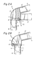
- Fig. 2A shows an example where both the pin "r" and the bolt 13 are provided at inner side of the shoulder block 3.
- Fig. 2B shows an example where the bolt is provided at the outer side of the shoulder block 3, while
- Fig. 2C shows an example where the bolt 13 is provided completely outside of the shoulder block but inwardly of the framework.
- Fig. 2A shows an example where both the pin "r" and the bolt 13 are provided at inner side of the shoulder block 3.
- Fig. 2B shows an example where the bolt is provided at the outer side of the shoulder block 3
- Fig. 2C shows an example where the bolt 13 is provided completely outside of the shoulder block but inwardly of the framework.
- the distal end of the movable plate "q" is bent round downwardly at the inner side of the bending part of the leg member 6 to form a hole for receiving the pin "r" or the distal end of the fixed plate p is suitably bent (not shown) to form such a hole or other methods will be available.
- Fig. 3 shows how the leg member 6 is folded at the shoulder block so as to reduce the bulkiness of the frame structure.
- Fig. 4 is a perspective view showing the detail of the shoulder block 3 and the condition where the movable plate has been swung out with the pin "r" as the pivoting center.
- Numeral 13' designates the bore for the bolt. This particular case exemplifies the example where the movable plate "q" is of relatively thick material and when the leg member 6 is connected and tightened with the bolt 13, the plate “q" is adequately accommodated in the box-like space provided by the lower edge part "p"', thus affording a sturdy construction.
- Fig. 1 shows how the leg member 6 is folded at the shoulder block so as to reduce the bulkiness of the frame structure.
- Fig. 4 is a perspective view showing the detail of the shoulder block 3 and the condition where the movable plate has been swung out with the pin "r" as the pivoting center.
- Numeral 13' designates the bore for the bolt
- FIG. 5 shows the condition in which the leg members at both sides of the framework 1 used for the collapsible membrane structure of the invention have been inwardly folded respectively to become compact and tightly joined together by suitable fastening means 15 and 16 to become ready for storage or transportation. Due to the fact that the radius of curvature of the shoulder block at the folding position has been so reduced that it may be possible to minimize the bulkiness of the framework in the vertical direction as viewed in Fig. 5 when the legs are folded.
- the hinge structure of this invention differs considerably from the conventional hinge type structure wherein two parts, each comprising a series of depressions and protrusions complementarily coupled through a hinge pin
- the construction according to the present invention may afford sufficient strength against the stress working at the folding part, whereby there is less possibility of the hinge part being damaged due to irregular or incidental external force which may be caused during use or transportation of the collapsible membrane structure.
- FIG. 6 showing another modification of the collapsible membrane structure of the present invention
- the details thereof are illustrated in front view where the frame structure with use of a ridge block 2a comprising 2 sets of hinge means 5a, 5a in a similar manner to Fig. 2 as the connection means at the top of the ridge of the right and left rafter members 4,4 is shown in a condition suitable for transportation.
- the connecting ridge block 2a comprises 2 sets of hinge means 5a and the rafter members 4 may be pivotably moved relative to the ridge block 2a through said hinge means, the rafter members 4, 4 may be pivoted to be in a substantially straight line, whereby the height of the framework may be remarkably reduced compared with the conventional one.
- the bolt 13a will be used to reinstate the rafter members to the roof shape.
- the beam similar to the beam 7 in Fig. 1 is eliminated; however, it may be used provided that each beam may be separated to agree with the extended condition of the rafter members.
- Figs. 7 and 8 illustrate examples of a retaining member to provide easier connection of the required frame members and/or auxiliary members and enable it to reduce projection of such retaining members outwardly of the framework.
- Fig. 7 shows the several configurations of the specially designed retaining member to be used as the connecting means at the locations at which the required frame members, and other reinforcement members and/or auxiliary members and the like are to be attached.
- Fig. 7A is a perspective view of such retaining member assembly and if such assemblies are fixed beforehand at the preselected locations of the respective members anticipated to be connected with other members, the other members would be easily connected with use of the bolt 13b. Furthermore, as shown in Fig.
- This configuration will provide convenience in selection of the fixing positions and reliable attachment of the other members. If it is preferable to fasten some members securely, two bolts may be used for fixing purposes so as to reduce the possibility of missing bolts by loosening at the specific portions. Furthermore, as shown at 8c in Fig. 8C safety may be increased by using an auxiliary plate "n" having a stopper "m” and providing a bore “m”' for receiving the stopper "m” and attaching the bolt through the bore of the auxiliary plate "n", then the bolt 13b may not tend to move toward the through-bore "j" where the bolt may be loosened from the retaining member.
- Fig. 8 in which the retaining member 8d similar to the one shown in Fig. 7B is used as the connection means.
- the retaining member is fixed to the leg member 6 for example, beforehand at the predetermined locations and is used as the connection means for the other members.
- it is used to connect a pipe 23 to the leg member 6 by means of a bolt 22a and a nut 22b.
- liner plate 21 having a bent locking projection 21', it will substantially avoid the possibility of the bolt 22a tending to move toward the open end of the longitudinal slot during use, thus easily providing a quite safe construction.
- retaining members at suitable places with suitable orientation with respect to the members forming the truss construction for the roof or the leg members to be folded condition as shown in Figs. 3, 5 or 6, it is possible to reduce the possibility that these retaining members may project outwardly of the framework or may cause interference with the other elements when the membrane structure is folded and collapsed. It is also possible to reduce the bulkiness of the membrane structure when collapsed by making the radius of curvature at the shoulder block of the hinge means between the rafter member and leg member smaller than that of the radius produced by bending of the elongated members as is done conventionally, resulting in convenience in stacking the frame structures for storage, less damage to the membrane and easier transportation leading to reduction in the transportation cost.
- Figs. 9 and 10 illustrating another form of the retaining member and the collapsible membrane structure.
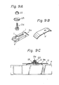
- the retaining members 8e having both ends made round as shown in Fig. 9A are secured to the outer surface of the frame members at the predetermined spaced positions and the bolts 13d are provided beforehand to stand through the longitudinal slot "i", while the through-holes 31 are provided beforehand in the membrane 12 at the positions and distances corresponding to those of the bolts and the membrane is spread over the frame members in a manner to match with the positions of the bolts and the holes in the membrane and the nuts 22 are tightened on the bolts 13d with the washers 23, thus making it easy to attach the membrane to the framework.
- Fig. 9b shows an auxiliary plate "n"'.
- Fig. 9C shows in section an example of attaching the membrane to the rafter member, in which the retaining members 8e are provided on the rafter members 4 and the membrane 12 is placed over the rafter members with the through holes 31 of the membrane aligned with the bolt and then the washers 23 are put on the retaining members and finally the nuts 22 are used to tightly secure the membrane.
- Fig. 10B shows how the membrane can be made much stronger and easier to install, thus improving working efficiency.
- Such a membrane includes the through-holes 31 for receiving bolts and is configured to enclose bands 32 made of hard plastic or metal plate wrapped integrally with the membrane, through-holes 31 being provided through the plastic bands as well.
- the retaining members 8e to be provided at outer surface of the framework for the collapsible membrane structure of the present invention are, as earlier mentioned, made round at the corner portions to provide various advantages such as improving the working efficiency for attaching the membrane, avoiding the possibility of damage to the membrane and so forth.
Landscapes
- Engineering & Computer Science (AREA)
- Architecture (AREA)
- Civil Engineering (AREA)
- Structural Engineering (AREA)
- Physics & Mathematics (AREA)
- Electromagnetism (AREA)
- Tents Or Canopies (AREA)
Claims (6)
Applications Claiming Priority (2)
| Application Number | Priority Date | Filing Date | Title |
|---|---|---|---|
| JP1981099568U JPS6012844Y2 (ja) | 1981-07-03 | 1981-07-03 | 可縮膜体構造物 |
| JP99568/81 | 1981-07-03 |
Publications (3)
| Publication Number | Publication Date |
|---|---|
| EP0069193A2 EP0069193A2 (de) | 1983-01-12 |
| EP0069193A3 EP0069193A3 (en) | 1983-08-24 |
| EP0069193B1 true EP0069193B1 (de) | 1987-02-25 |
Family
ID=14250725
Family Applications (1)
| Application Number | Title | Priority Date | Filing Date |
|---|---|---|---|
| EP82101836A Expired EP0069193B1 (de) | 1981-07-03 | 1982-03-08 | Mit einer Membran versehene zusammenklappbare Konstruktion |
Country Status (4)
| Country | Link |
|---|---|
| EP (1) | EP0069193B1 (de) |
| JP (1) | JPS6012844Y2 (de) |
| BR (1) | BR8203896A (de) |
| DE (1) | DE3275472D1 (de) |
Families Citing this family (6)
| Publication number | Priority date | Publication date | Assignee | Title |
|---|---|---|---|---|
| GB8431050D0 (en) * | 1984-12-08 | 1985-01-16 | Portakabin Ltd | Pitched roof assembly |
| JP2592059B2 (ja) * | 1985-04-04 | 1997-03-19 | ドゥ・ポッテ−ル・ダンドィユ、エリック・アンヌ−アンリ・マリ−・ギスレン | 伸縮可能な構造物 |
| JPH01191631A (ja) * | 1988-01-27 | 1989-08-01 | Dainippon Jochugiku Co Ltd | 電気蚊取器 |
| FR2721057B1 (fr) * | 1994-06-08 | 1996-09-06 | Dominique Marie Yves Guerin | Chapiteau pliable et dépliable rapidement. |
| JP7318923B2 (ja) * | 2019-09-30 | 2023-08-01 | 明治商工株式会社 | 歩行者保護用の移動式防護塀 |
| CN120100081B (zh) * | 2025-05-07 | 2025-07-04 | 湖南善弘电子技术有限公司 | 一种便于移动运输的可拓展式太阳能房箱 |
Family Cites Families (4)
| Publication number | Priority date | Publication date | Assignee | Title |
|---|---|---|---|---|
| US1871634A (en) * | 1930-12-03 | 1932-08-16 | William R Tingle | Folding article of furniture |
| GB982411A (en) * | 1961-12-27 | 1965-02-03 | Karl Heinz Klahold | Collapsible tent frame |
| FR1551593A (de) * | 1967-05-08 | 1968-12-27 | ||
| GB2094367A (en) * | 1981-02-27 | 1982-09-15 | Hyde Peter Jeremy | Tents |
-
1981
- 1981-07-03 JP JP1981099568U patent/JPS6012844Y2/ja not_active Expired
-
1982
- 1982-03-08 EP EP82101836A patent/EP0069193B1/de not_active Expired
- 1982-03-08 DE DE8282101836T patent/DE3275472D1/de not_active Expired
- 1982-07-02 BR BR8203896A patent/BR8203896A/pt unknown
Also Published As
| Publication number | Publication date |
|---|---|
| EP0069193A3 (en) | 1983-08-24 |
| BR8203896A (pt) | 1983-06-28 |
| JPS585501U (ja) | 1983-01-13 |
| DE3275472D1 (en) | 1987-04-02 |
| EP0069193A2 (de) | 1983-01-12 |
| JPS6012844Y2 (ja) | 1985-04-24 |
Similar Documents
| Publication | Publication Date | Title |
|---|---|---|
| US4834254A (en) | Frame structure | |
| US5700102A (en) | Shelter frame connector system | |
| US8776815B2 (en) | Mounting assembly for a collapsible canopy | |
| US8245479B2 (en) | Hinge connector for connecting structural frame members | |
| US4244384A (en) | Modular shelter system | |
| US4171598A (en) | Hollow boom construction | |
| EP0112309B1 (de) | Lagergestell | |
| EP0069193A2 (de) | Mit einer Membran versehene zusammenklappbare Konstruktion | |
| US6578339B1 (en) | Sectional tower with intermediate legs | |
| JP3700952B2 (ja) | 支保工 | |
| US4193414A (en) | Collapsible and portable structure | |
| CA2066339C (en) | Pool wall construction | |
| US4216895A (en) | Method of forming hollow boom | |
| US20070187179A1 (en) | Scaffold Support Bracket and Assembly | |
| US4828074A (en) | Truck scaffolding | |
| JP3624907B2 (ja) | 屋根化粧パネル取付金具 | |
| US5125761A (en) | Seismic hold down device | |
| JPH033714Y2 (de) | ||
| EP1745185B1 (de) | Klappbares witterungsschutzmodul und aufbauverfahren dafür | |
| JP4097532B2 (ja) | 親綱用支柱 | |
| JP3049171B2 (ja) | リターナブルケース | |
| JPH082165Y2 (ja) | デッキプレートを使用したシエルターの接合構造 | |
| JP3049172B2 (ja) | リターナブルケース | |
| CA2286961A1 (en) | Truss assembly | |
| JP4292302B2 (ja) | 屋根トラス |
Legal Events
| Date | Code | Title | Description |
|---|---|---|---|
| PUAI | Public reference made under article 153(3) epc to a published international application that has entered the european phase |
Free format text: ORIGINAL CODE: 0009012 |
|
| AK | Designated contracting states |
Kind code of ref document: A2 Designated state(s): DE FR GB |
|
| PUAL | Search report despatched |
Free format text: ORIGINAL CODE: 0009013 |
|
| AK | Designated contracting states |
Kind code of ref document: A3 Designated state(s): DE FR GB |
|
| 17P | Request for examination filed |
Effective date: 19831020 |
|
| GRAA | (expected) grant |
Free format text: ORIGINAL CODE: 0009210 |
|
| AK | Designated contracting states |
Kind code of ref document: B1 Designated state(s): DE FR GB |
|
| REF | Corresponds to: |
Ref document number: 3275472 Country of ref document: DE Date of ref document: 19870402 |
|
| ET | Fr: translation filed | ||
| PLBE | No opposition filed within time limit |
Free format text: ORIGINAL CODE: 0009261 |
|
| STAA | Information on the status of an ep patent application or granted ep patent |
Free format text: STATUS: NO OPPOSITION FILED WITHIN TIME LIMIT |
|
| 26N | No opposition filed | ||
| PGFP | Annual fee paid to national office [announced via postgrant information from national office to epo] |
Ref country code: GB Payment date: 19920225 Year of fee payment: 11 |
|
| PGFP | Annual fee paid to national office [announced via postgrant information from national office to epo] |
Ref country code: FR Payment date: 19920327 Year of fee payment: 11 |
|
| PGFP | Annual fee paid to national office [announced via postgrant information from national office to epo] |
Ref country code: DE Payment date: 19920331 Year of fee payment: 11 |
|
| PG25 | Lapsed in a contracting state [announced via postgrant information from national office to epo] |
Ref country code: GB Effective date: 19930308 |
|
| GBPC | Gb: european patent ceased through non-payment of renewal fee |
Effective date: 19930308 |
|
| PG25 | Lapsed in a contracting state [announced via postgrant information from national office to epo] |
Ref country code: FR Effective date: 19931130 |
|
| PG25 | Lapsed in a contracting state [announced via postgrant information from national office to epo] |
Ref country code: DE Effective date: 19931201 |
|
| REG | Reference to a national code |
Ref country code: FR Ref legal event code: ST |