EP0069352A1 - Verfahren und Vorrichtung zur Messung des Durchmessers von optischen Fasern - Google Patents
Verfahren und Vorrichtung zur Messung des Durchmessers von optischen Fasern Download PDFInfo
- Publication number
- EP0069352A1 EP0069352A1 EP82105882A EP82105882A EP0069352A1 EP 0069352 A1 EP0069352 A1 EP 0069352A1 EP 82105882 A EP82105882 A EP 82105882A EP 82105882 A EP82105882 A EP 82105882A EP 0069352 A1 EP0069352 A1 EP 0069352A1
- Authority
- EP
- European Patent Office
- Prior art keywords
- fibre
- variations
- capacitor
- diameter
- plates
- Prior art date
- Legal status (The legal status is an assumption and is not a legal conclusion. Google has not performed a legal analysis and makes no representation as to the accuracy of the status listed.)
- Granted
Links
- 239000013307 optical fiber Substances 0.000 title claims abstract description 4
- 238000000034 method Methods 0.000 title claims description 14
- 239000000835 fiber Substances 0.000 claims abstract description 55
- 239000003990 capacitor Substances 0.000 claims abstract description 34
- 125000006850 spacer group Chemical group 0.000 claims description 4
- 238000011144 upstream manufacturing Methods 0.000 claims description 3
- 238000004804 winding Methods 0.000 claims description 3
- 238000005259 measurement Methods 0.000 description 8
- 230000010355 oscillation Effects 0.000 description 6
- 238000005253 cladding Methods 0.000 description 2
- 230000003287 optical effect Effects 0.000 description 2
- VGGSQFUCUMXWEO-UHFFFAOYSA-N Ethene Chemical compound C=C VGGSQFUCUMXWEO-UHFFFAOYSA-N 0.000 description 1
- 239000005977 Ethylene Substances 0.000 description 1
- 101100400378 Mus musculus Marveld2 gene Proteins 0.000 description 1
- 239000004809 Teflon Substances 0.000 description 1
- 229920006362 Teflon® Polymers 0.000 description 1
- 230000001627 detrimental effect Effects 0.000 description 1
- 238000006073 displacement reaction Methods 0.000 description 1
- 230000005684 electric field Effects 0.000 description 1
- 238000003780 insertion Methods 0.000 description 1
- 230000037431 insertion Effects 0.000 description 1
- 239000000463 material Substances 0.000 description 1
- 239000011159 matrix material Substances 0.000 description 1
- 238000000691 measurement method Methods 0.000 description 1
- 239000012528 membrane Substances 0.000 description 1
- 238000012986 modification Methods 0.000 description 1
- 230000004048 modification Effects 0.000 description 1
- 238000012545 processing Methods 0.000 description 1
- 238000009877 rendering Methods 0.000 description 1
- 230000000007 visual effect Effects 0.000 description 1
Images
Classifications
-
- G—PHYSICS
- G01—MEASURING; TESTING
- G01B—MEASURING LENGTH, THICKNESS OR SIMILAR LINEAR DIMENSIONS; MEASURING ANGLES; MEASURING AREAS; MEASURING IRREGULARITIES OF SURFACES OR CONTOURS
- G01B7/00—Measuring arrangements characterised by the use of electric or magnetic techniques
- G01B7/12—Measuring arrangements characterised by the use of electric or magnetic techniques for measuring diameters
- G01B7/125—Measuring arrangements characterised by the use of electric or magnetic techniques for measuring diameters of objects while moving
-
- C—CHEMISTRY; METALLURGY
- C03—GLASS; MINERAL OR SLAG WOOL
- C03B—MANUFACTURE, SHAPING, OR SUPPLEMENTARY PROCESSES
- C03B37/00—Manufacture or treatment of flakes, fibres, or filaments from softened glass, minerals, or slags
- C03B37/01—Manufacture of glass fibres or filaments
- C03B37/02—Manufacture of glass fibres or filaments by drawing or extruding, e.g. direct drawing of molten glass from nozzles; Cooling fins therefor
- C03B37/025—Manufacture of glass fibres or filaments by drawing or extruding, e.g. direct drawing of molten glass from nozzles; Cooling fins therefor from reheated softened tubes, rods, fibres or filaments, e.g. drawing fibres from preforms
- C03B37/0253—Controlling or regulating
Definitions
- the present invention relates to a process and an apparatus for measuring the diameter of optical fibres, more particularly fibres which are being drawn.
- One of these methods makes use of a laser beam which is moved back and forth on a plane perpendicular to the fibre and is collected by a photodiode.
- the diameter size can be deduced from the knowledge of the speed of the beam motion and from the measurement of the darkening time.
- this method requires expensive apparatuses and allows measurements with a resolution of the order of the micron, which can be insufficient.
- a second known method consists in focusing on a diode matrix, through a conventional optical system (for instance a micro - 1 scope objective), the light emitted by a fixed source: the fibre diameter can be obtained from the size of the shadow.
- This method is well suited to measurements on fibre trunks already produced, for instance for laboratory purposes; yet, during fibre drawing, fibre vibrations may cause important errors, so that repeated measures and heavy signal processings are necessary to obtain reliable values.
- the process according to the invention is characterized in that the fibre, while being drawn, is made to pass between the plates of a parallel-plate capacitor, and there are detected the capacitance variations due to the changes in the dielectric constant in the space between the plates, caused by the introduction of the fibre into said space and by the diameter variations along the fibre, which together with the air or another gas between the two plates forms the capacitor dielectric.
- the capacitor can be a constant charge capacitor, more particularly an electret capacitor: in this way the capacitance variations can be measured from variations of potential, which are easier to detect.
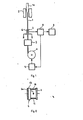
- the apparatus apt to carry out the process is characterized in that it comprises a parallel-plate capacitor, placed along the fibre drawing path, upstream the winding drum, so that the fibre passes between the two plates, and connected to means detecting the capacitance variations occurring in the capacitor due to the passage of the fibre and/or to the fibre diameter variations, the means detecting the capacitance variations being in turn connected to means for calculating, on the basis of such capacitance variations, the fibre diameter or its variations.
- a motor 5 driven by a motor 5.
- Equation (1) is obtained by solving the Lapace equation in the dielectric between the plates, with the suitable boundary conditions, and considering the fibre insertion as a perturbation.
- Capacitor 6, 7 is connected to a capacitance measuring device 8, apt to measure the value of ⁇ C or the variations of such a value caused by changes in the fibre diameter.
- the capacitance measuring device 8 can be connected in turn to a computing device 9, which gives the radius (or diameter) value and is possibly associated with a display (not shown), which gives a visual image of the diameter behaviour.
- the circuit measuring the capacitance variations can be inserted into a feedback loop for the control of the speed of motor 5 driving drum 4, so that any capacitance variation due to the fibre diameter variations causes a variation of the drawing speed such as to annul the variation itself.
- the capacitor 6, 7 can be inserted into a bridge, which is at balance in correspondence with the nominal diameter of fibre l(known a priori) or is balanced by using a sample fibre of that particular diameter.
- the capacitor can be inserted into an os- scillating circuit whose resonance frequency depends on the value of the capacitor capacitance, and the capacitance or the capacitance variations can be detected by the beat of the frequency of that oscillating circuit and the frequency of a second oscillating circuit having about the same resonance frequency as the first one.
- Advantageously capacitor 6, 7 can be of the constant charge type, for instance of the type in which one of the plates, e.g. plate 6, consists of an electret, as shown in Fig. 2, where 6b denotes the electrized membrane joined to the supporting element 6a.
- the ratio is equal to : the measurement of the capacitance variation can then be replaced by voltage variation measurements, which are relatively simpler.
- the variation measuring circuit can in fact be replaced by a simple differential amplifier.
- Said spacers are also to maintain the parallelism between the plates necessary to the application of relation (1) and to prevent relative oscillations of the plates, which may give rise to spurious capacitance changes which may be detrimental to the measurement.
- spacers 10,11 will have such thickness as to prevent the capacitor discharge, taking into account the plate potential and the dielectric strength of the medium between the plates;obviously the thickness must be higher than the maximum estimated diameter of the fibre.
- the dielectric is air, which has a dielectric strength of the order of 2KV/mm
- values of capacitor charge and plate distance will be suitable that give a potential-to- distance ratio of about one hundred volts per millimeter.
Landscapes
- Chemical & Material Sciences (AREA)
- Engineering & Computer Science (AREA)
- Physics & Mathematics (AREA)
- Manufacturing & Machinery (AREA)
- General Life Sciences & Earth Sciences (AREA)
- Materials Engineering (AREA)
- Organic Chemistry (AREA)
- Life Sciences & Earth Sciences (AREA)
- General Physics & Mathematics (AREA)
- Geochemistry & Mineralogy (AREA)
- Length Measuring Devices By Optical Means (AREA)
- Measurement Of Length, Angles, Or The Like Using Electric Or Magnetic Means (AREA)
- Length Measuring Devices With Unspecified Measuring Means (AREA)
- Glass Compositions (AREA)
- Measurement Of Resistance Or Impedance (AREA)
- Testing Of Optical Devices Or Fibers (AREA)
- Treatment Of Fiber Materials (AREA)
- Laser Surgery Devices (AREA)
- Manufacture, Treatment Of Glass Fibers (AREA)
Priority Applications (1)
| Application Number | Priority Date | Filing Date | Title |
|---|---|---|---|
| AT82105882T ATE13947T1 (de) | 1981-07-06 | 1982-07-01 | Verfahren und vorrichtung zur messung des durchmessers von optischen fasern. |
Applications Claiming Priority (2)
| Application Number | Priority Date | Filing Date | Title |
|---|---|---|---|
| IT67936/81A IT1144279B (it) | 1981-07-06 | 1981-07-06 | Procedimento ed apparecchiatura per la misura del diametro di fibre ottiche |
| IT6793681 | 1981-07-06 |
Publications (2)
| Publication Number | Publication Date |
|---|---|
| EP0069352A1 true EP0069352A1 (de) | 1983-01-12 |
| EP0069352B1 EP0069352B1 (de) | 1985-06-19 |
Family
ID=11306506
Family Applications (1)
| Application Number | Title | Priority Date | Filing Date |
|---|---|---|---|
| EP82105882A Expired EP0069352B1 (de) | 1981-07-06 | 1982-07-01 | Verfahren und Vorrichtung zur Messung des Durchmessers von optischen Fasern |
Country Status (12)
| Country | Link |
|---|---|
| US (1) | US4523938A (de) |
| EP (1) | EP0069352B1 (de) |
| JP (1) | JPS587505A (de) |
| AT (1) | ATE13947T1 (de) |
| AU (1) | AU550133B2 (de) |
| BR (1) | BR8203823A (de) |
| CA (1) | CA1221138A (de) |
| DE (2) | DE3264262D1 (de) |
| DK (1) | DK150862C (de) |
| ES (1) | ES513588A0 (de) |
| IT (1) | IT1144279B (de) |
| NO (1) | NO157355C (de) |
Cited By (2)
| Publication number | Priority date | Publication date | Assignee | Title |
|---|---|---|---|---|
| EP0174017A1 (de) * | 1984-09-06 | 1986-03-12 | CSELT Centro Studi e Laboratori Telecomunicazioni S.p.A. | Kapazitive Vorrichtung zum Messen des Durchmessers einer dielektrischen Faser |
| EP0701105A1 (de) * | 1994-09-12 | 1996-03-13 | AT&T Corp. | Verfahren und Vorrichtung zum Regeln der Dimensionen des Querschnitts einer optischer Faser während ihrer Herstellung |
Families Citing this family (24)
| Publication number | Priority date | Publication date | Assignee | Title |
|---|---|---|---|---|
| JPS6029769U (ja) * | 1983-08-06 | 1985-02-28 | 三菱自動車工業株式会社 | 車両用パワ−ステアリング装置 |
| US4594763A (en) * | 1984-12-21 | 1986-06-17 | At&T Technologies, Inc. | Method and apparatus for inserting a glass rod into a glass tube |
| US4600424A (en) * | 1985-03-21 | 1986-07-15 | Flaming Dale G | Method of forming an ultrafine micropipette |
| IN169141B (de) * | 1985-08-21 | 1991-09-07 | Stc Plc | |
| JP2765033B2 (ja) * | 1989-04-14 | 1998-06-11 | 住友電気工業株式会社 | 光ファイバーの線引方法 |
| US5443610A (en) * | 1994-01-29 | 1995-08-22 | Corning Incorporated | Apparatus for controlling fiber diameter during drawing |
| EP0881196B1 (de) * | 1997-05-30 | 2001-04-25 | Shin-Etsu Chemical Company, Ltd. | Verfahren zum Ziehen einer Glasvorform zu einem Stab |
| US5908484A (en) * | 1998-10-16 | 1999-06-01 | Lucent Technologies Inc. | Method of making a coated optical fiber comprising measuring the delamination resistance of the coating |
| JP5460346B2 (ja) * | 2010-01-15 | 2014-04-02 | 古河電気工業株式会社 | 光ファイバの線引き方法 |
| CN103929562B (zh) * | 2014-04-29 | 2017-08-01 | 威海华菱光电股份有限公司 | 图像传感器、图像扫描和厚度检测方法 |
| CN103925867A (zh) * | 2014-04-29 | 2014-07-16 | 威海华菱光电股份有限公司 | 厚度传感器和厚度测量方法 |
| CN103971445A (zh) * | 2014-05-13 | 2014-08-06 | 威海华菱光电股份有限公司 | 纸币厚度的检测装置 |
| CN103971446A (zh) * | 2014-05-13 | 2014-08-06 | 威海华菱光电股份有限公司 | 纸币厚度的检测工装 |
| CN103985189A (zh) * | 2014-05-13 | 2014-08-13 | 威海华菱光电股份有限公司 | 纸币厚度的测量装置 |
| CN103968749A (zh) * | 2014-05-16 | 2014-08-06 | 威海华菱光电股份有限公司 | 物体厚度检测装置及其检测方法 |
| EP3158284B1 (de) | 2014-06-17 | 2022-03-16 | Heraeus Quartz North America LLC | Vorrichtung und verfahren zur erwärmung und vermessung von transparenten zylinderförmigen artikeln |
| CN105136011B (zh) * | 2015-09-30 | 2018-09-14 | 威海华菱光电股份有限公司 | 膜厚的检测装置 |
| CN105136012A (zh) * | 2015-09-30 | 2015-12-09 | 威海华菱光电股份有限公司 | 膜厚的检测装置 |
| CN105318819B (zh) * | 2015-11-04 | 2018-09-18 | 威海华菱光电股份有限公司 | 膜厚的检测装置 |
| CN105318820A (zh) * | 2015-11-05 | 2016-02-10 | 威海华菱光电股份有限公司 | 厚度传感器 |
| US10421268B2 (en) * | 2015-11-18 | 2019-09-24 | Stratasys, Inc. | Filament feeding device having a capacitive filament displacement sensor for use in additive manufacturing system |
| CN105333809A (zh) * | 2015-12-04 | 2016-02-17 | 威海华菱光电股份有限公司 | 厚度检测传感器 |
| CN106197248B (zh) * | 2016-07-21 | 2018-05-29 | 威海华菱光电股份有限公司 | 膜厚的检测装置 |
| CN115093113B (zh) * | 2022-06-17 | 2023-12-05 | 中国工程物理研究院激光聚变研究中心 | 一种用于微纳光纤拉制的直径在线监控系统 |
Citations (5)
| Publication number | Priority date | Publication date | Assignee | Title |
|---|---|---|---|---|
| US2516768A (en) * | 1946-04-29 | 1950-07-25 | Zellweger Uster Ag | Apparatus for gauging textiles, particularly yarns and sliver |
| GB680695A (en) * | 1950-02-09 | 1952-10-08 | Rene Visele | Improvements in devices for controlling the thickness of products in the form of yarns, strips, sheets and the like |
| GB855595A (en) * | 1956-05-11 | 1960-12-07 | British Nylon Spinners Ltd | Improvements relating to the electrical measurement of the thickness of a thread |
| US3879660A (en) * | 1973-10-24 | 1975-04-22 | John S Piso | Capacitive measuring system |
| GB2020816A (en) * | 1977-08-09 | 1979-11-21 | Micro Sensors Inc | Capacitive Measuring System with Automatic Calibration Means |
Family Cites Families (5)
| Publication number | Priority date | Publication date | Assignee | Title |
|---|---|---|---|---|
| US3088297A (en) * | 1960-06-01 | 1963-05-07 | American Optical Corp | Apparatus for drawing fibers |
| NL120426C (de) * | 1961-07-25 | |||
| US3865564A (en) * | 1973-07-09 | 1975-02-11 | Bell Telephone Labor Inc | Fabrication of glass fibers from preform by lasers |
| CH603842A5 (de) * | 1975-10-10 | 1978-08-31 | Peyer Siegfried | |
| JPS5311039A (en) * | 1976-07-19 | 1978-02-01 | Hitachi Ltd | Controller of diameter of optical fiber |
-
1981
- 1981-07-06 IT IT67936/81A patent/IT1144279B/it active
-
1982
- 1982-06-22 AU AU85088/82A patent/AU550133B2/en not_active Ceased
- 1982-06-23 JP JP57106981A patent/JPS587505A/ja active Granted
- 1982-06-23 DK DK281582A patent/DK150862C/da not_active IP Right Cessation
- 1982-06-23 CA CA000405823A patent/CA1221138A/en not_active Expired
- 1982-06-30 BR BR8203823A patent/BR8203823A/pt unknown
- 1982-06-30 ES ES513588A patent/ES513588A0/es active Granted
- 1982-07-01 DE DE8282105882T patent/DE3264262D1/de not_active Expired
- 1982-07-01 EP EP82105882A patent/EP0069352B1/de not_active Expired
- 1982-07-01 DE DE198282105882T patent/DE69352T1/de active Pending
- 1982-07-01 AT AT82105882T patent/ATE13947T1/de not_active IP Right Cessation
- 1982-07-02 US US06/394,535 patent/US4523938A/en not_active Expired - Fee Related
- 1982-07-05 NO NO822345A patent/NO157355C/no unknown
Patent Citations (5)
| Publication number | Priority date | Publication date | Assignee | Title |
|---|---|---|---|---|
| US2516768A (en) * | 1946-04-29 | 1950-07-25 | Zellweger Uster Ag | Apparatus for gauging textiles, particularly yarns and sliver |
| GB680695A (en) * | 1950-02-09 | 1952-10-08 | Rene Visele | Improvements in devices for controlling the thickness of products in the form of yarns, strips, sheets and the like |
| GB855595A (en) * | 1956-05-11 | 1960-12-07 | British Nylon Spinners Ltd | Improvements relating to the electrical measurement of the thickness of a thread |
| US3879660A (en) * | 1973-10-24 | 1975-04-22 | John S Piso | Capacitive measuring system |
| GB2020816A (en) * | 1977-08-09 | 1979-11-21 | Micro Sensors Inc | Capacitive Measuring System with Automatic Calibration Means |
Cited By (2)
| Publication number | Priority date | Publication date | Assignee | Title |
|---|---|---|---|---|
| EP0174017A1 (de) * | 1984-09-06 | 1986-03-12 | CSELT Centro Studi e Laboratori Telecomunicazioni S.p.A. | Kapazitive Vorrichtung zum Messen des Durchmessers einer dielektrischen Faser |
| EP0701105A1 (de) * | 1994-09-12 | 1996-03-13 | AT&T Corp. | Verfahren und Vorrichtung zum Regeln der Dimensionen des Querschnitts einer optischer Faser während ihrer Herstellung |
Also Published As
| Publication number | Publication date |
|---|---|
| CA1221138A (en) | 1987-04-28 |
| DK281582A (da) | 1983-01-07 |
| IT1144279B (it) | 1986-10-29 |
| US4523938A (en) | 1985-06-18 |
| NO157355B (no) | 1987-11-23 |
| IT8167936A0 (it) | 1981-07-06 |
| JPH0134321B2 (de) | 1989-07-19 |
| JPS587505A (ja) | 1983-01-17 |
| BR8203823A (pt) | 1983-06-28 |
| DE3264262D1 (en) | 1985-07-25 |
| AU550133B2 (en) | 1986-03-06 |
| ES8305121A1 (es) | 1983-03-16 |
| DK150862B (da) | 1987-07-06 |
| ES513588A0 (es) | 1983-03-16 |
| EP0069352B1 (de) | 1985-06-19 |
| AU8508882A (en) | 1983-01-13 |
| DK150862C (da) | 1988-01-11 |
| ATE13947T1 (de) | 1985-07-15 |
| NO822345L (no) | 1983-01-07 |
| NO157355C (no) | 1988-03-02 |
| DE69352T1 (de) | 1983-04-28 |
Similar Documents
| Publication | Publication Date | Title |
|---|---|---|
| EP0069352A1 (de) | Verfahren und Vorrichtung zur Messung des Durchmessers von optischen Fasern | |
| EP0144437B1 (de) | Rheometer | |
| EP0354882B1 (de) | Fiberoptischer Schwingungsfühler | |
| EP0174017B1 (de) | Kapazitive Vorrichtung zum Messen des Durchmessers einer dielektrischen Faser | |
| US4226538A (en) | Device for detecting irregularities in a moving sheet material | |
| US4321464A (en) | Device for measuring vibration phase and amplitude | |
| Rodriguez-Cobo et al. | Speckle characterization in multimode fibers for sensing applications | |
| US2142854A (en) | Viscosimeter | |
| US4218614A (en) | Device for measuring vibration amplitude | |
| CA1124100A (en) | Optical measuring apparatus employing a laser | |
| Chitnis et al. | Optical fiber sensor for vibration amplitude measurement | |
| EP0093890B1 (de) | Apparat zur Detektion von Oberflächenunregelmässigkeiten auf einem strangförmigen Material | |
| US5207766A (en) | Fiber-optic vibration sensor | |
| EP0482545B1 (de) | Einrichtung zum Messen der Charakteristiken wie insbesondere der Brechungsindexverteilung optischer Komponenten | |
| Lopez-Higuera et al. | New low-cost fiber optic accelerometer system for stator winding monitoring of hydroelectric generating machines | |
| SU1383267A1 (ru) | Волоконно-оптический датчик переменного электрического и магнитного полей | |
| EP0113453B1 (de) | Messmethode für die Grenzwellenlänge in optischen Fibern | |
| RU2758814C1 (ru) | Микро-опто-электромеханический компенсационный преобразователь линейных ускорений с контурами грубо-точной стабилизации чувствительного элемента | |
| SU1150504A1 (ru) | Оптоэлектронный датчик давлени | |
| SU1626230A1 (ru) | Волоконно-оптический датчик электрических напр жений | |
| SU1744593A1 (ru) | Вибрационный вискозиметр | |
| JPH09251036A (ja) | 光電界センサ及びこれを用いた光計器用変圧器 | |
| SU1231411A1 (ru) | Оптико-электронное устройство дл измерени амплитуд акустических колебаний поверхности | |
| EP0013725A1 (de) | System zum Fernmessen von Weiten | |
| JPS568841A (en) | Measuring method of micro probe deep level |
Legal Events
| Date | Code | Title | Description |
|---|---|---|---|
| PUAI | Public reference made under article 153(3) epc to a published international application that has entered the european phase |
Free format text: ORIGINAL CODE: 0009012 |
|
| AK | Designated contracting states |
Designated state(s): AT BE CH DE FR GB LI NL SE |
|
| TCAT | At: translation of patent claims filed | ||
| EL | Fr: translation of claims filed | ||
| 17P | Request for examination filed |
Effective date: 19830126 |
|
| DET | De: translation of patent claims | ||
| TCNL | Nl: translation of patent claims filed | ||
| GRAA | (expected) grant |
Free format text: ORIGINAL CODE: 0009210 |
|
| AK | Designated contracting states |
Designated state(s): AT BE CH DE FR GB LI NL SE |
|
| REF | Corresponds to: |
Ref document number: 13947 Country of ref document: AT Date of ref document: 19850715 Kind code of ref document: T |
|
| REF | Corresponds to: |
Ref document number: 3264262 Country of ref document: DE Date of ref document: 19850725 |
|
| ET | Fr: translation filed | ||
| PLBE | No opposition filed within time limit |
Free format text: ORIGINAL CODE: 0009261 |
|
| STAA | Information on the status of an ep patent application or granted ep patent |
Free format text: STATUS: NO OPPOSITION FILED WITHIN TIME LIMIT |
|
| 26N | No opposition filed | ||
| PGFP | Annual fee paid to national office [announced via postgrant information from national office to epo] |
Ref country code: BE Payment date: 19900430 Year of fee payment: 9 |
|
| PGFP | Annual fee paid to national office [announced via postgrant information from national office to epo] |
Ref country code: GB Payment date: 19900619 Year of fee payment: 9 |
|
| PGFP | Annual fee paid to national office [announced via postgrant information from national office to epo] |
Ref country code: SE Payment date: 19900620 Year of fee payment: 9 |
|
| PGFP | Annual fee paid to national office [announced via postgrant information from national office to epo] |
Ref country code: CH Payment date: 19900726 Year of fee payment: 9 |
|
| PGFP | Annual fee paid to national office [announced via postgrant information from national office to epo] |
Ref country code: FR Payment date: 19900727 Year of fee payment: 9 |
|
| PGFP | Annual fee paid to national office [announced via postgrant information from national office to epo] |
Ref country code: NL Payment date: 19900731 Year of fee payment: 9 Ref country code: DE Payment date: 19900731 Year of fee payment: 9 |
|
| PGFP | Annual fee paid to national office [announced via postgrant information from national office to epo] |
Ref country code: AT Payment date: 19901127 Year of fee payment: 9 |
|
| PG25 | Lapsed in a contracting state [announced via postgrant information from national office to epo] |
Ref country code: GB Effective date: 19910701 Ref country code: AT Effective date: 19910701 |
|
| PG25 | Lapsed in a contracting state [announced via postgrant information from national office to epo] |
Ref country code: SE Effective date: 19910702 |
|
| PG25 | Lapsed in a contracting state [announced via postgrant information from national office to epo] |
Ref country code: LI Effective date: 19910731 Ref country code: CH Effective date: 19910731 Ref country code: BE Effective date: 19910731 |
|
| BERE | Be: lapsed |
Owner name: CSELT CENTRO STUDI E LABORATORI TELECOMUNICAZIONI Effective date: 19910731 |
|
| PG25 | Lapsed in a contracting state [announced via postgrant information from national office to epo] |
Ref country code: NL Effective date: 19920201 |
|
| GBPC | Gb: european patent ceased through non-payment of renewal fee | ||
| NLV4 | Nl: lapsed or anulled due to non-payment of the annual fee | ||
| PG25 | Lapsed in a contracting state [announced via postgrant information from national office to epo] |
Ref country code: FR Effective date: 19920331 |
|
| REG | Reference to a national code |
Ref country code: CH Ref legal event code: PL |
|
| PG25 | Lapsed in a contracting state [announced via postgrant information from national office to epo] |
Ref country code: DE Effective date: 19920401 |
|
| REG | Reference to a national code |
Ref country code: FR Ref legal event code: ST |
|
| EUG | Se: european patent has lapsed |
Ref document number: 82105882.3 Effective date: 19920210 |