EP0069979B1 - Circuit d'adaptation d'antennes - Google Patents
Circuit d'adaptation d'antennes Download PDFInfo
- Publication number
- EP0069979B1 EP0069979B1 EP82106058A EP82106058A EP0069979B1 EP 0069979 B1 EP0069979 B1 EP 0069979B1 EP 82106058 A EP82106058 A EP 82106058A EP 82106058 A EP82106058 A EP 82106058A EP 0069979 B1 EP0069979 B1 EP 0069979B1
- Authority
- EP
- European Patent Office
- Prior art keywords
- frequency
- matching
- transmitter
- switches
- antenna
- Prior art date
- Legal status (The legal status is an assumption and is not a legal conclusion. Google has not performed a legal analysis and makes no representation as to the accuracy of the status listed.)
- Expired
Links
Images
Classifications
-
- H—ELECTRICITY
- H04—ELECTRIC COMMUNICATION TECHNIQUE
- H04B—TRANSMISSION
- H04B1/00—Details of transmission systems, not covered by a single one of groups H04B3/00 - H04B13/00; Details of transmission systems not characterised by the medium used for transmission
- H04B1/02—Transmitters
- H04B1/04—Circuits
- H04B1/0458—Arrangements for matching and coupling between power amplifier and antenna or between amplifying stages
-
- H—ELECTRICITY
- H03—ELECTRONIC CIRCUITRY
- H03H—IMPEDANCE NETWORKS, e.g. RESONANT CIRCUITS; RESONATORS
- H03H11/00—Networks using active elements
- H03H11/02—Multiple-port networks
- H03H11/28—Impedance matching networks
- H03H11/30—Automatic matching of source impedance to load impedance
-
- H—ELECTRICITY
- H03—ELECTRONIC CIRCUITRY
- H03J—TUNING RESONANT CIRCUITS; SELECTING RESONANT CIRCUITS
- H03J5/00—Discontinuous tuning; Selecting predetermined frequencies; Selecting frequency bands with or without continuous tuning in one or more of the bands, e.g. push-button tuning, turret tuner
- H03J5/24—Discontinuous tuning; Selecting predetermined frequencies; Selecting frequency bands with or without continuous tuning in one or more of the bands, e.g. push-button tuning, turret tuner with a number of separate pretuned tuning circuits or separate tuning elements selectively brought into circuit, e.g. for waveband selection or for television channel selection
- H03J5/242—Discontinuous tuning; Selecting predetermined frequencies; Selecting frequency bands with or without continuous tuning in one or more of the bands, e.g. push-button tuning, turret tuner with a number of separate pretuned tuning circuits or separate tuning elements selectively brought into circuit, e.g. for waveband selection or for television channel selection used exclusively for band selection
Definitions
- the invention relates to an antenna matching device according to the preamble of the main claim.
- An antenna matching device of this type is known (US Pat. No. 3,129,386). Exactly as much tunable coils as transmission frequencies are provided, which can be interconnected via synchronous multiple switches with appropriate capacitors to form matching branches, so that a matching branch tuned to the same frequency is switched on for each adjustable transmitting frequency between transmitter and antenna.
- Such a known antenna matching device would not be suitable for transmitters that can be switched very quickly between successive transmission frequencies.
- Modern transmitters as will be used in future radio transmission processes with a very rapid, sudden frequency change according to a predetermined frequency scheme, can be switched in frequency in the range of milliseconds or even microseconds. It would not be possible to switch over at the same speed in the known branches in the adaptation branches.
- the matching branches represent high-quality resonant circuits in which high reactive powers occur. Switches that can switch relatively high powers must therefore be used to switch the coils and capacitors, especially if the device is to be used for a transmitter with a relatively high output power.
- switches for higher power loads for example conventional vacuum relays, have relatively slow switching times.
- fast-switching semiconductor switches such as those used in the transmitter, and as a result of which the short switching times mentioned above are possible cannot be used in such matching devices because of the higher power load. So far, the speed of the frequency switching in devices of this type has been determined exclusively by the speed with which the adapter can be switched in frequency, in practice switching times of at most a few milliseconds can be achieved. This is too slow for various applications mentioned above, for example in the military field.
- the measure according to the invention of providing two or more separate antenna matching branches makes it possible to tune another branch to the frequency following in the frequency diagram or even to tune several other branches to the frequencies following in the frequency diagram while transmitting via one branch tuned to the current transmission frequency , so that when the transmitter is subsequently switched over, the next branch that has already been coordinated only has to be switched on using the quickly switchable switches.
- the quickly switchable switches provided for switching on the branches are designed, for example, as semiconductor switches, just like in the transmitter. Although relatively slow switches for tuning the dummy elements to the predetermined frequencies are still provided in the individual adaptation branches, the device according to the invention can be used to switch very quickly from one transmission frequency to the next.
- the device according to the invention is particularly advantageous for transmit antennas whose transmitter works according to the frequency hopping method.
- Broadband antennas that are mechanically very long and wide have mostly been used for this purpose.
- Such known antenna systems are very unsuitable, for example, in the military field on vehicles.
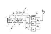
- the figure shows a conventional high-frequency transmitter T, for example for the frequency range between 20 and 80 MHz, it consists of a tunable oscillator 0, a power amplifier V and a downstream tunable filter F.
- the individual frequency-determining elements of the transmitter T are via a control line L by a control device R tunable.
- the desired frequency scheme is programmed into the control device R; in the exemplary embodiment shown, it is entered, for example, that the transmitter T should be switched very quickly in the frequency sequence f1, f3, f7 ... fx, that is to say in a predetermined sequence of the transmission frequency of the selected frequency band .
- the output of the transmitter is connected via very fast switches S1, S2, Sx to individual tuning branches A1, A2, Ax, which are connected to the antenna B on the output side. If necessary, additional fast switches connected synchronously with the switches on the input side can also be arranged between antenna B and matching branches.
- the switches S1, S2, Sx are preferably semiconductor switches which can be switched in the microsecond range.
- Each matching branch A1, A2, Ax is designed in a known manner and its reactance resistors can in turn be tuned to the various transmission frequencies entered there by means of relatively slow circuit breakers, for example reed relays, controlled by the control device R.
- the stored frequency sequence of the control device R is fixed, it must also be known on the receiving side.
- the first matching branch A1 is controlled by the control device R to the frequency f1, just like the transmitter T, and the switch S1 is closed, i. H. the transmitter transmits via the adaptation branch A1 and the antenna B.
- the second adaptation branch A2 is tuned to the frequency f3 that follows in the diagram. If the transmitter T is then switched to the next transmission frequency f3 via the control device R, S1 is simultaneously opened and S2 closed, that is to say the matching branch A2 to the antenna B which was previously tuned to the frequency f3. If three or more adaptation branches are provided, the adjustment time of the adaptation device can of course be shortened accordingly. It is also possible to provide as many matching branches A1 to Ax as the transmission frequencies f1 to fx. In this case, the branches only need to be tuned once to the respective frequency; when changing the frequency, only the associated switches S1 to Sx then have to be actuated.
Landscapes
- Engineering & Computer Science (AREA)
- Computer Networks & Wireless Communication (AREA)
- Signal Processing (AREA)
- Transmitters (AREA)
Claims (3)
Applications Claiming Priority (2)
| Application Number | Priority Date | Filing Date | Title |
|---|---|---|---|
| DE3127566A DE3127566C2 (de) | 1981-07-11 | 1981-07-11 | Antennenanpasseinrichtung für einen nach dem Frequenzsprung-Verfahren arbeitenden Hochfrequenzsender |
| DE3127566 | 1981-07-11 |
Publications (4)
| Publication Number | Publication Date |
|---|---|
| EP0069979A2 EP0069979A2 (fr) | 1983-01-19 |
| EP0069979A3 EP0069979A3 (en) | 1984-10-03 |
| EP0069979B1 true EP0069979B1 (fr) | 1986-12-03 |
| EP0069979B2 EP0069979B2 (fr) | 1991-01-23 |
Family
ID=6136758
Family Applications (1)
| Application Number | Title | Priority Date | Filing Date |
|---|---|---|---|
| EP82106058A Expired - Lifetime EP0069979B2 (fr) | 1981-07-11 | 1982-07-07 | Circuit d'adaptation d'antennes |
Country Status (3)
| Country | Link |
|---|---|
| US (1) | US4521913A (fr) |
| EP (1) | EP0069979B2 (fr) |
| DE (2) | DE3127566C2 (fr) |
Families Citing this family (22)
| Publication number | Priority date | Publication date | Assignee | Title |
|---|---|---|---|---|
| FR2574597B1 (fr) * | 1984-12-06 | 1986-12-26 | Commissariat Energie Atomique | Dispositif d'accord d'antenne haute frequence |
| US4689803A (en) * | 1985-06-10 | 1987-08-25 | Megapulse Inc. | Antenna tuning system and method |
| IN165870B (fr) * | 1985-06-25 | 1990-02-03 | Siemens Ag | |
| DE3527554A1 (de) * | 1985-08-01 | 1987-02-12 | Rohde & Schwarz | System zum betrieb eines kurzwellensenders nach dem frequenzsprungverfahren |
| US5034697A (en) * | 1989-06-09 | 1991-07-23 | United States Of America As Represented By The Secretary Of The Navy | Magnetic amplifier switch for automatic tuning of VLF transmitting antenna |
| DE3929702A1 (de) * | 1989-09-07 | 1991-03-14 | Standard Elektrik Lorenz Ag | Schaltungsanordnung zum gegeneinander entkoppelten verbinden mehrerer nach dem frequenzsprung-verfahren arbeitender sender an eine antenne |
| US5231355A (en) * | 1990-06-18 | 1993-07-27 | The Charles Machine Works, Inc. | Locator transmitter having an automatically tuned antenna |
| FR2666417B1 (fr) * | 1990-08-31 | 1993-03-26 | Tekelec Airtronic Sa | Procede pour controler le fonctionnement d'un systeme comprenant un arrangement de filtre et un dispositif utilisateur tel qu'une antenne relie a ce dernier, et agencement pour la mise en óoeuvre de ce procede. |
| US5287550A (en) * | 1990-12-24 | 1994-02-15 | Motorola, Inc. | Simulcast scheduler |
| CA2061385C (fr) * | 1991-02-19 | 1996-12-24 | Kazuhiro Kudoh | Recepteur de radiomessagerie |
| DE4116126A1 (de) * | 1991-05-17 | 1992-11-19 | Telefunken Systemtechnik | Sendeeinrichtung fuer den frequenz-hopping-betrieb |
| DE4124601A1 (de) * | 1991-07-25 | 1993-01-28 | Telefunken Sendertechnik | Nachstimmeinrichtung fuer lang- und laengstwellenantennen |
| JP2866775B2 (ja) * | 1991-12-26 | 1999-03-08 | 三星電子株式会社 | アンテナ移動装置及びその方法 |
| JPH0722971A (ja) * | 1993-07-06 | 1995-01-24 | Mitsubishi Electric Corp | 無線通信機 |
| JP3444653B2 (ja) * | 1994-06-09 | 2003-09-08 | 三菱電機株式会社 | 電力増幅器 |
| JP2944444B2 (ja) * | 1995-01-12 | 1999-09-06 | 日本電気株式会社 | 携帯無線機 |
| EP0850512B1 (fr) * | 1995-09-15 | 1999-07-07 | Siemens Aktiengesellschaft | Appareil radio a plusieurs plages de frequences |
| FI114259B (fi) * | 1999-07-14 | 2004-09-15 | Filtronic Lk Oy | Radiotaajuisen etupään rakenne |
| JP2002171111A (ja) * | 2000-12-04 | 2002-06-14 | Anten Corp | 携帯無線機及び携帯無線機用アンテナ |
| US7433647B2 (en) * | 2005-05-12 | 2008-10-07 | Lear Corporation | Transmit antenna multiplexing for vehicular passive entry systems |
| JP4637774B2 (ja) * | 2006-03-17 | 2011-02-23 | 富士通株式会社 | 移動通信端末 |
| US8472904B2 (en) * | 2009-03-30 | 2013-06-25 | The Charles Stark Draper Laboratory, Inc. | Antenna with integrated tuning detection elements |
Family Cites Families (7)
| Publication number | Priority date | Publication date | Assignee | Title |
|---|---|---|---|---|
| US3129386A (en) * | 1962-05-21 | 1964-04-14 | Sunair Electronics Inc | Automatic antenna impedance matching and loading unit |
| US3277377A (en) * | 1963-10-25 | 1966-10-04 | Gen Motors Corp | Coupling circuit for all-transistor high frequency transmitter |
| US3566273A (en) * | 1968-06-07 | 1971-02-23 | Paul R Johannessen | Broadband high-q antenna system |
| US3794941A (en) * | 1972-05-08 | 1974-02-26 | Hughes Aircraft Co | Automatic antenna impedance tuner including digital control circuits |
| US3883875A (en) * | 1974-01-02 | 1975-05-13 | Int Standard Electric Corp | Endfire commutated antenna array |
| US3906405A (en) * | 1974-07-01 | 1975-09-16 | Motorola Inc | Tunable antenna coupling circuit |
| US4143369A (en) * | 1977-10-25 | 1979-03-06 | Northrop Corporation | Iff diversity switch |
-
1981
- 1981-07-11 DE DE3127566A patent/DE3127566C2/de not_active Expired
-
1982
- 1982-07-07 EP EP82106058A patent/EP0069979B2/fr not_active Expired - Lifetime
- 1982-07-07 DE DE8282106058T patent/DE3274606D1/de not_active Expired
- 1982-07-09 US US06/396,715 patent/US4521913A/en not_active Expired - Fee Related
Also Published As
| Publication number | Publication date |
|---|---|
| DE3127566A1 (de) | 1983-01-27 |
| EP0069979A2 (fr) | 1983-01-19 |
| DE3274606D1 (en) | 1987-01-15 |
| US4521913A (en) | 1985-06-04 |
| DE3127566C2 (de) | 1984-03-08 |
| EP0069979A3 (en) | 1984-10-03 |
| EP0069979B2 (fr) | 1991-01-23 |
Similar Documents
| Publication | Publication Date | Title |
|---|---|---|
| EP0069979B1 (fr) | Circuit d'adaptation d'antennes | |
| DE69706044T2 (de) | Zwischenverstärker mit variabler bandbreite | |
| DE102014119624B4 (de) | Abstimmbarer Hochfrequenzfilter mit niedriger Dämpfung | |
| DE2828838C2 (de) | HF-Eingangsschaltung für Fernsehempfänger | |
| DE102012203215B4 (de) | Hochfrequenzschaltmodul | |
| DE102011111951A1 (de) | Einstellbares Filter, einstellbarer Duplexer und damit arbeitendes mobiles Nachrichtenendgerät | |
| DE2645018A1 (de) | Adaptiver amplitudenentzerrer | |
| DE2924043C2 (de) | Entzerrungsnetzwerk | |
| DE3311640C2 (fr) | ||
| DE3509516C1 (de) | Schaltungsanordnung der Eingangsstufen eines Fernsehtuners | |
| EP0405349B1 (fr) | Appareil d'émission et/ou de réception | |
| DE2553211C2 (de) | Ankoppelschaltung zum Betrieb von zwei Rundfunkempfängern mit einer einzigen Antenne | |
| EP0042853B1 (fr) | Dispositif d'entree accordable pour couplage d'un recepteur | |
| DE2660472C2 (de) | Kaskaden-Filtersystem, bei dem zwei Schwingungsquellen mit unterschiedlichen Frequenzen abwechselnd oder gleichzeitig auf einen gemeinsamen Verbraucher arbeiten | |
| DE60100421T2 (de) | Multimodales Kommunikationsgerät mit einem Sendeempfänger mit mehreren Eingängen | |
| DE3020135C2 (de) | Schaltungsanordnung für die selbsttätige Einstellung eines Funkempfängers auf einen Sender | |
| EP1110317B1 (fr) | Appareil de reception radio | |
| DE4227833C2 (de) | Zwischenfrequenzfilter für einen Funkempfänger | |
| DE10251203B3 (de) | Verfahren und Schaltungsanordnung zum Einspeisen eines Eingangssignales in n Empfänger | |
| DE963613C (de) | Kombinierter Fernseh- und UKW-Rundfunkempfaenger | |
| DE3938510A1 (de) | Antennen-zusatzverstaerkerschaltung | |
| EP1150442B1 (fr) | Circuit en diversité d'antennes pour récepteur radio avec plusieurs parties de réception | |
| EP0316611B1 (fr) | Installation de transmission radio THF comportant au moins deux transmetteurs à fréquence différente | |
| DE681128C (de) | Kopplungseinrichtung | |
| DE3007554A1 (de) | Anpassungsschaltung fuer die anschaltung einer hochfrequenzquelle, insbesondere eines senders und/oder empfaengers, an ein belastungsnetzwerk |
Legal Events
| Date | Code | Title | Description |
|---|---|---|---|
| PUAI | Public reference made under article 153(3) epc to a published international application that has entered the european phase |
Free format text: ORIGINAL CODE: 0009012 |
|
| AK | Designated contracting states |
Designated state(s): BE DE FR GB NL |
|
| PUAL | Search report despatched |
Free format text: ORIGINAL CODE: 0009013 |
|
| AK | Designated contracting states |
Designated state(s): BE DE FR GB NL |
|
| 17P | Request for examination filed |
Effective date: 19840920 |
|
| GRAA | (expected) grant |
Free format text: ORIGINAL CODE: 0009210 |
|
| AK | Designated contracting states |
Kind code of ref document: B1 Designated state(s): BE DE FR GB NL |
|
| REF | Corresponds to: |
Ref document number: 3274606 Country of ref document: DE Date of ref document: 19870115 |
|
| ET | Fr: translation filed | ||
| PLBI | Opposition filed |
Free format text: ORIGINAL CODE: 0009260 |
|
| 26 | Opposition filed |
Opponent name: SIEMENS AKTIENGESELLSCHAFT, BERLIN UND MUENCHEN Effective date: 19870722 |
|
| NLR1 | Nl: opposition has been filed with the epo |
Opponent name: SIEMENS AKTIENGESELLSCHAFT, |
|
| PUAH | Patent maintained in amended form |
Free format text: ORIGINAL CODE: 0009272 |
|
| STAA | Information on the status of an ep patent application or granted ep patent |
Free format text: STATUS: PATENT MAINTAINED AS AMENDED |
|
| 27A | Patent maintained in amended form |
Effective date: 19910123 |
|
| AK | Designated contracting states |
Kind code of ref document: B2 Designated state(s): BE DE FR GB NL |
|
| NLR2 | Nl: decision of opposition | ||
| NLR3 | Nl: receipt of modified translations in the netherlands language after an opposition procedure | ||
| ET3 | Fr: translation filed ** decision concerning opposition | ||
| PGFP | Annual fee paid to national office [announced via postgrant information from national office to epo] |
Ref country code: GB Payment date: 19910619 Year of fee payment: 10 |
|
| PGFP | Annual fee paid to national office [announced via postgrant information from national office to epo] |
Ref country code: NL Payment date: 19910731 Year of fee payment: 10 |
|
| PGFP | Annual fee paid to national office [announced via postgrant information from national office to epo] |
Ref country code: DE Payment date: 19910812 Year of fee payment: 10 |
|
| PG25 | Lapsed in a contracting state [announced via postgrant information from national office to epo] |
Ref country code: GB Effective date: 19920707 |
|
| PGFP | Annual fee paid to national office [announced via postgrant information from national office to epo] |
Ref country code: BE Payment date: 19920715 Year of fee payment: 11 |
|
| PG25 | Lapsed in a contracting state [announced via postgrant information from national office to epo] |
Ref country code: NL Effective date: 19930201 |
|
| GBPC | Gb: european patent ceased through non-payment of renewal fee |
Effective date: 19920707 |
|
| NLV4 | Nl: lapsed or anulled due to non-payment of the annual fee | ||
| PG25 | Lapsed in a contracting state [announced via postgrant information from national office to epo] |
Ref country code: DE Effective date: 19930401 |
|
| PG25 | Lapsed in a contracting state [announced via postgrant information from national office to epo] |
Ref country code: BE Effective date: 19930731 |
|
| BERE | Be: lapsed |
Owner name: ROHDE & SCHWARZ G.M.B.H. & CO. K.G. Effective date: 19930731 |
|
| PGFP | Annual fee paid to national office [announced via postgrant information from national office to epo] |
Ref country code: FR Payment date: 19970729 Year of fee payment: 16 |
|
| PG25 | Lapsed in a contracting state [announced via postgrant information from national office to epo] |
Ref country code: FR Free format text: LAPSE BECAUSE OF NON-PAYMENT OF DUE FEES Effective date: 19990331 |
|
| REG | Reference to a national code |
Ref country code: FR Ref legal event code: ST |