EP0070005A1 - Circuit de fluide hydraulique d'un excavateur hydraulique - Google Patents
Circuit de fluide hydraulique d'un excavateur hydraulique Download PDFInfo
- Publication number
- EP0070005A1 EP0070005A1 EP82106156A EP82106156A EP0070005A1 EP 0070005 A1 EP0070005 A1 EP 0070005A1 EP 82106156 A EP82106156 A EP 82106156A EP 82106156 A EP82106156 A EP 82106156A EP 0070005 A1 EP0070005 A1 EP 0070005A1
- Authority
- EP
- European Patent Office
- Prior art keywords
- control valve
- hydraulic
- directional control
- cylinder
- hydraulic fluid
- Prior art date
- Legal status (The legal status is an assumption and is not a legal conclusion. Google has not performed a legal analysis and makes no representation as to the accuracy of the status listed.)
- Granted
Links
- 239000012530 fluid Substances 0.000 title claims abstract description 42
- 238000010276 construction Methods 0.000 description 4
- 238000010586 diagram Methods 0.000 description 3
- 238000004519 manufacturing process Methods 0.000 description 3
- 238000009412 basement excavation Methods 0.000 description 1
- 238000009434 installation Methods 0.000 description 1
- 238000004904 shortening Methods 0.000 description 1
Images


Classifications
-
- E—FIXED CONSTRUCTIONS
- E02—HYDRAULIC ENGINEERING; FOUNDATIONS; SOIL SHIFTING
- E02F—DREDGING; SOIL-SHIFTING
- E02F9/00—Component parts of dredgers or soil-shifting machines, not restricted to one of the kinds covered by groups E02F3/00 - E02F7/00
- E02F9/20—Drives; Control devices
- E02F9/22—Hydraulic or pneumatic drives
- E02F9/2221—Control of flow rate; Load sensing arrangements
- E02F9/2239—Control of flow rate; Load sensing arrangements using two or more pumps with cross-assistance
-
- E—FIXED CONSTRUCTIONS
- E02—HYDRAULIC ENGINEERING; FOUNDATIONS; SOIL SHIFTING
- E02F—DREDGING; SOIL-SHIFTING
- E02F9/00—Component parts of dredgers or soil-shifting machines, not restricted to one of the kinds covered by groups E02F3/00 - E02F7/00
- E02F9/20—Drives; Control devices
- E02F9/22—Hydraulic or pneumatic drives
- E02F9/2278—Hydraulic circuits
- E02F9/2292—Systems with two or more pumps
-
- F—MECHANICAL ENGINEERING; LIGHTING; HEATING; WEAPONS; BLASTING
- F15—FLUID-PRESSURE ACTUATORS; HYDRAULICS OR PNEUMATICS IN GENERAL
- F15B—SYSTEMS ACTING BY MEANS OF FLUIDS IN GENERAL; FLUID-PRESSURE ACTUATORS, e.g. SERVOMOTORS; DETAILS OF FLUID-PRESSURE SYSTEMS, NOT OTHERWISE PROVIDED FOR
- F15B11/00—Servomotor systems without provision for follow-up action; Circuits therefor
- F15B11/16—Servomotor systems without provision for follow-up action; Circuits therefor with two or more servomotors
- F15B11/17—Servomotor systems without provision for follow-up action; Circuits therefor with two or more servomotors using two or more pumps
-
- F—MECHANICAL ENGINEERING; LIGHTING; HEATING; WEAPONS; BLASTING
- F15—FLUID-PRESSURE ACTUATORS; HYDRAULICS OR PNEUMATICS IN GENERAL
- F15B—SYSTEMS ACTING BY MEANS OF FLUIDS IN GENERAL; FLUID-PRESSURE ACTUATORS, e.g. SERVOMOTORS; DETAILS OF FLUID-PRESSURE SYSTEMS, NOT OTHERWISE PROVIDED FOR
- F15B2211/00—Circuits for servomotor systems
- F15B2211/20—Fluid pressure source, e.g. accumulator or variable axial piston pump
- F15B2211/205—Systems with pumps
- F15B2211/20576—Systems with pumps with multiple pumps
-
- F—MECHANICAL ENGINEERING; LIGHTING; HEATING; WEAPONS; BLASTING
- F15—FLUID-PRESSURE ACTUATORS; HYDRAULICS OR PNEUMATICS IN GENERAL
- F15B—SYSTEMS ACTING BY MEANS OF FLUIDS IN GENERAL; FLUID-PRESSURE ACTUATORS, e.g. SERVOMOTORS; DETAILS OF FLUID-PRESSURE SYSTEMS, NOT OTHERWISE PROVIDED FOR
- F15B2211/00—Circuits for servomotor systems
- F15B2211/30—Directional control
- F15B2211/305—Directional control characterised by the type of valves
- F15B2211/30505—Non-return valves, i.e. check valves
-
- F—MECHANICAL ENGINEERING; LIGHTING; HEATING; WEAPONS; BLASTING
- F15—FLUID-PRESSURE ACTUATORS; HYDRAULICS OR PNEUMATICS IN GENERAL
- F15B—SYSTEMS ACTING BY MEANS OF FLUIDS IN GENERAL; FLUID-PRESSURE ACTUATORS, e.g. SERVOMOTORS; DETAILS OF FLUID-PRESSURE SYSTEMS, NOT OTHERWISE PROVIDED FOR
- F15B2211/00—Circuits for servomotor systems
- F15B2211/30—Directional control
- F15B2211/305—Directional control characterised by the type of valves
- F15B2211/3056—Assemblies of multiple valves
- F15B2211/30565—Assemblies of multiple valves having multiple valves for a single output member, e.g. for creating higher valve function by use of multiple valves like two 2/2-valves replacing a 5/3-valve
-
- F—MECHANICAL ENGINEERING; LIGHTING; HEATING; WEAPONS; BLASTING
- F15—FLUID-PRESSURE ACTUATORS; HYDRAULICS OR PNEUMATICS IN GENERAL
- F15B—SYSTEMS ACTING BY MEANS OF FLUIDS IN GENERAL; FLUID-PRESSURE ACTUATORS, e.g. SERVOMOTORS; DETAILS OF FLUID-PRESSURE SYSTEMS, NOT OTHERWISE PROVIDED FOR
- F15B2211/00—Circuits for servomotor systems
- F15B2211/30—Directional control
- F15B2211/305—Directional control characterised by the type of valves
- F15B2211/3056—Assemblies of multiple valves
- F15B2211/3059—Assemblies of multiple valves having multiple valves for multiple output members
- F15B2211/30595—Assemblies of multiple valves having multiple valves for multiple output members with additional valves between the groups of valves for multiple output members
-
- F—MECHANICAL ENGINEERING; LIGHTING; HEATING; WEAPONS; BLASTING
- F15—FLUID-PRESSURE ACTUATORS; HYDRAULICS OR PNEUMATICS IN GENERAL
- F15B—SYSTEMS ACTING BY MEANS OF FLUIDS IN GENERAL; FLUID-PRESSURE ACTUATORS, e.g. SERVOMOTORS; DETAILS OF FLUID-PRESSURE SYSTEMS, NOT OTHERWISE PROVIDED FOR
- F15B2211/00—Circuits for servomotor systems
- F15B2211/70—Output members, e.g. hydraulic motors or cylinders or control therefor
- F15B2211/71—Multiple output members, e.g. multiple hydraulic motors or cylinders
- F15B2211/7142—Multiple output members, e.g. multiple hydraulic motors or cylinders the output members being arranged in multiple groups
Definitions
- This invention relates to a hydraulic fluid circuit of a hydraulic shovel.
- 17 is a pilot pump, 18 a relief valve and 19 is a control pilot valve for the boom control valves 13 and 14.
- 20 is a control pilot valve for the arm control valve 15, and 21 a control pilot valve for the bucket control valve 16.
- the hydraulic cylinders 6-8 are shortened when the pilot valves 19-21 are each brought to position A, and lengthened when they are each brought to position B.
- the boom cylinder 6 When the pilot valve 19 is actuated to operate the boom cylinder 6, the boom cylinder 6 receives a supply of hydraulic fluid from the hydraulic pumps 9 and 10 via the two control valves 13 and 14, so that the boom cylinder 6 operates at high speed. However, when the pilot valve 20 is actuated to operate the arm cylinder it is only from the hydraulic pump 9 that the hydraulic fluid is supplied to the arm cylinder 7 via the single directional control valve 15. Thus the arm cylinder 7 operates at low speed, and the hydraulic pump 10 is not utilized to actuate the arm cylinder 7.
- the invention has been developed for the purpose of obviating the aforesaid problems of the prior art. Accordingly the invention has as its object the provision of a hydraulic fluid circuit of a hydraulic shovel capable of increasing the speed at which the two hydraulic cylinders in the front of the hydraulic shovel, making effective use of the hydraulic pumps, reducing production cost and obviating the problem of securing space of installation.
- the outstanding characteristic of the invention for accomplishing the aforesaid object is that, in a hydraulic fluid circuit of a hydraulic shovel comprising a first hydraulic pump and a second hydraulic pump respectively connected to a first directional control valve group and a second directional control valve group, a first hydraulic cylinder and a second hydraulic cylinder are respectively connected to first and second directional control valves of the first directional control valve group, a first working port of a third directional control valve of the second directional control valve group is connected to one cylinder chamber of the first hydraulic cylinder and a second working port of the third directional control valve is connected to one cylinder chamber of the second hydraulic cylinder.
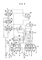
- Fig. 3 shows the hydraulic fluid circuit of a loading shovel comprising one embodiment of the invention.
- 22 is a directional control valve of the first directional control valve group 11, and 23 and 24 are pilot ports of the directional control valve 22.
- 25 and 26 are working ports of the directional control valve 22.
- 27 and 28 are lines for connecting the working ports 25 and 26 to bottom side chambers of the arm cylinder 7 and the bucket cylinder 8 respectively.
- 29 and 30 are check valves mounted in the lines 27 and 28 respectively.
- 31 is a pilot line connecting an output port 32 of the pilot valve 20 to the pilot port 23.
- 33 is a change-over valve normally disposed in position n and changing to position m when a pilot pressure is produced at the output port 32.
- an output port 34 of the pilot valve 21 communicates with the pilot port 24; when the change-over valve 33 is in position m, the pilot port 24 communicates with a tank.
- the arm control valve 15 and bucket control valve 16 are arranged in the second directional control valve group 12.
- the bucket control valve 16 and directional control valve 22 are actuated since the change-over valve 33 is in position n, so that the hydraulic fluid is supplied from the hydraulic pumps 9 and 10 to a bottom side chamber of the bucket cylinder 8 to lengthen the bucket cylinder 8 at high speed.
- the pilot valves 20 and 21 are brought to position B simultaneously, the hydraulic fluid is supplied from the hydraulic pumps 9 and 10 to the bottom side chamber of the arm cylinder 7 because the change-over valve 33 moves to position m, so that the arm cylinder 7 is lenthened at high speed.
- the bottom side chamber of the bucket cylinder 8 only receives hydraulic fluid from the hydraulic pump 10, so that the bucket cylinder is lengthened at normal speed.
- the embodiment of the hydraulic fluid circuit of the aforesaid construction in conformity with the invention has been shown and described as being of a loading shovel. However, it would be apparent that the hydraulic fluid circuit described herein can be used with a hydraulic shovel having a back for the front.
- the directional control valve 22 is automatically switched when the pilot valves 20 and 21 are actuated. However, an additional pilot valve for actuating the direction control valve 22 may be used.
- the directional control valves 13-15 and 22 used are of the pilot type.
- the invention is not limited to this specific type of directional control valves and the directional control valves may be of a mechanical type or an electromagnetic type.
- the hydraulic fluid may be supplied from the hydraulic pumps 9 and 10 to the hydraulic cylinders 7 and 8 when they are shortened.
- the bottom side chambers of the hydraulic cylinders 7 and 8 each have a pressure receiving area about twice as large as that of the rod side chambers thereof, and a higher speed is required for lengthening the hydraulic cylinders 7 and 8 than for shortening them.
- it is effective to supply the hydraulic fluid from the hydraulic pumps 9 and 10 to the hydraulic
- the speed at which lengthening of the arm cylinder 7 is obtained is increased when the pilot valves 20 and 21 are simultaneously brought to position B.
- the speed at which the bucket cylinder 8 is increased may be increased in place of the speed at which the arm cylinder is lengthened.
- the invention enables the speed at which two hydraulic cylinders are lengthened can be increased by merely adding another directional control valve to the directional control valves used heretofore, so that the efficienty with which excavation is carried out can be improved and the hydraulic pumps can be made effective use of. Since only one directional control valve is added, no appreciable increase in cost is involved. Since no increase in the size of the directional control valve groups is involved, no problem is raised as to the space for installing the circuit. Moreover, the hydraulic fluid circuit according to the invention is easy to maintain.
Landscapes
- Engineering & Computer Science (AREA)
- General Engineering & Computer Science (AREA)
- Physics & Mathematics (AREA)
- Fluid Mechanics (AREA)
- Mining & Mineral Resources (AREA)
- Civil Engineering (AREA)
- Structural Engineering (AREA)
- Mechanical Engineering (AREA)
- Operation Control Of Excavators (AREA)
- Fluid-Pressure Circuits (AREA)
Applications Claiming Priority (2)
| Application Number | Priority Date | Filing Date | Title |
|---|---|---|---|
| JP1981101830U JPS5810960U (ja) | 1981-07-10 | 1981-07-10 | 油圧ショベルの油圧回路 |
| JP101830/81U | 1981-07-10 |
Publications (2)
| Publication Number | Publication Date |
|---|---|
| EP0070005A1 true EP0070005A1 (fr) | 1983-01-19 |
| EP0070005B1 EP0070005B1 (fr) | 1986-02-19 |
Family
ID=14311009
Family Applications (1)
| Application Number | Title | Priority Date | Filing Date |
|---|---|---|---|
| EP82106156A Expired EP0070005B1 (fr) | 1981-07-10 | 1982-07-09 | Circuit de fluide hydraulique d'un excavateur hydraulique |
Country Status (5)
| Country | Link |
|---|---|
| US (1) | US4534268A (fr) |
| EP (1) | EP0070005B1 (fr) |
| JP (1) | JPS5810960U (fr) |
| KR (1) | KR870000935Y1 (fr) |
| DE (1) | DE3269163D1 (fr) |
Cited By (2)
| Publication number | Priority date | Publication date | Assignee | Title |
|---|---|---|---|---|
| GB2143304A (en) * | 1983-05-31 | 1985-02-06 | Komatsu Mfg Co Ltd | Directional control valve unit |
| CN119061970A (zh) * | 2024-09-30 | 2024-12-03 | 徐州徐工挖掘机械有限公司 | 推土铲可浮动升降的推土液压系统和挖掘机 |
Families Citing this family (8)
| Publication number | Priority date | Publication date | Assignee | Title |
|---|---|---|---|---|
| JPS6233950A (ja) * | 1985-08-06 | 1987-02-13 | Hitachi Constr Mach Co Ltd | 油圧機械の油圧回路 |
| US4838756A (en) * | 1987-02-19 | 1989-06-13 | Deere & Company | Hydraulic system for an industrial machine |
| US4984427A (en) * | 1989-09-01 | 1991-01-15 | Kabushiki Kaisha Kobe Seiko Sho | Control circuit for hydraulic actuator |
| JP3019671B2 (ja) * | 1993-05-27 | 2000-03-13 | ダイキン工業株式会社 | 超高圧制御装置 |
| JPH07238575A (ja) * | 1994-02-28 | 1995-09-12 | Komatsu Ltd | 走行用油圧装置 |
| JPH1113091A (ja) * | 1997-06-23 | 1999-01-19 | Hitachi Constr Mach Co Ltd | 建設機械の油圧駆動装置 |
| JP4721353B2 (ja) * | 2006-06-29 | 2011-07-13 | キャタピラー エス エー アール エル | 弁制御装置 |
| EP3660228B1 (fr) * | 2017-07-27 | 2022-04-20 | Sumitomo (S.H.I.) Construction Machinery Co., Ltd. | Pelleteuse |
Citations (6)
| Publication number | Priority date | Publication date | Assignee | Title |
|---|---|---|---|---|
| FR1431905A (fr) * | 1965-02-05 | 1966-03-18 | Auxitra Soc | Perfectionnements à la commande d'engins de travaux publics à plusieurs moteurs ouvérins |
| DE2138986A1 (de) * | 1971-08-04 | 1973-02-15 | Rexroth Gmbh G L | Steuerung fuer hydraulische antriebe |
| FR2169212A1 (fr) * | 1972-01-24 | 1973-09-07 | Kubota Ltd | |
| GB1405724A (en) * | 1972-01-27 | 1975-09-10 | Weyhausen G F | Hydraulic control for hydraulically operated working devices |
| US4207740A (en) * | 1979-06-12 | 1980-06-17 | Akermans Verkstad Ab | Valve blocks, in particular for hydraulic excavators |
| DE2856093A1 (de) * | 1978-12-23 | 1980-06-26 | Massey Ferguson Hanomag Inc & | Hydraulikanlage zur betaetigung von auf fahrzeugen aufgebauten arbeitsgeraeten, wie z.b. hydraulikbaggern, ladevorrichtungen usw. |
Family Cites Families (4)
| Publication number | Priority date | Publication date | Assignee | Title |
|---|---|---|---|---|
| US3760689A (en) * | 1972-02-24 | 1973-09-25 | Harnischfeger Corp | Control system for automatically sequencing operation of a plurality of hydraulic pumps for supplying a plurality of hydraulic actuators |
| US4142445A (en) * | 1977-03-17 | 1979-03-06 | Caterpillar Tractor Co. | Crossover plural circuit fluid system |
| US4073141A (en) * | 1977-03-17 | 1978-02-14 | Caterpillar Tractor Co. | Fluid control system with priority flow |
| JPS55120802U (fr) * | 1979-02-20 | 1980-08-27 |
-
1981
- 1981-07-10 JP JP1981101830U patent/JPS5810960U/ja active Granted
-
1982
- 1982-07-09 US US06/396,878 patent/US4534268A/en not_active Expired - Lifetime
- 1982-07-09 KR KR2019820005421U patent/KR870000935Y1/ko not_active Expired
- 1982-07-09 DE DE8282106156T patent/DE3269163D1/de not_active Expired
- 1982-07-09 EP EP82106156A patent/EP0070005B1/fr not_active Expired
Patent Citations (6)
| Publication number | Priority date | Publication date | Assignee | Title |
|---|---|---|---|---|
| FR1431905A (fr) * | 1965-02-05 | 1966-03-18 | Auxitra Soc | Perfectionnements à la commande d'engins de travaux publics à plusieurs moteurs ouvérins |
| DE2138986A1 (de) * | 1971-08-04 | 1973-02-15 | Rexroth Gmbh G L | Steuerung fuer hydraulische antriebe |
| FR2169212A1 (fr) * | 1972-01-24 | 1973-09-07 | Kubota Ltd | |
| GB1405724A (en) * | 1972-01-27 | 1975-09-10 | Weyhausen G F | Hydraulic control for hydraulically operated working devices |
| DE2856093A1 (de) * | 1978-12-23 | 1980-06-26 | Massey Ferguson Hanomag Inc & | Hydraulikanlage zur betaetigung von auf fahrzeugen aufgebauten arbeitsgeraeten, wie z.b. hydraulikbaggern, ladevorrichtungen usw. |
| US4207740A (en) * | 1979-06-12 | 1980-06-17 | Akermans Verkstad Ab | Valve blocks, in particular for hydraulic excavators |
Non-Patent Citations (1)
| Title |
|---|
| Patent Abstracts of Japan, Vol. 1, No. 40, 21 April 1977, page 2543M76, & JP-A-51 148 171 * |
Cited By (2)
| Publication number | Priority date | Publication date | Assignee | Title |
|---|---|---|---|---|
| GB2143304A (en) * | 1983-05-31 | 1985-02-06 | Komatsu Mfg Co Ltd | Directional control valve unit |
| CN119061970A (zh) * | 2024-09-30 | 2024-12-03 | 徐州徐工挖掘机械有限公司 | 推土铲可浮动升降的推土液压系统和挖掘机 |
Also Published As
| Publication number | Publication date |
|---|---|
| US4534268A (en) | 1985-08-13 |
| DE3269163D1 (en) | 1986-03-27 |
| EP0070005B1 (fr) | 1986-02-19 |
| JPS5810960U (ja) | 1983-01-24 |
| KR870000935Y1 (ko) | 1987-03-14 |
| KR840000545U (ko) | 1984-02-24 |
| JPH0245316Y2 (fr) | 1990-11-30 |
Similar Documents
| Publication | Publication Date | Title |
|---|---|---|
| US6026730A (en) | Flow control apparatus in a hydraulic circuit | |
| EP0087748B1 (fr) | Circuit hydraulique pour engin de construction | |
| US5081837A (en) | Hydraulic control circuit | |
| EP0070005A1 (fr) | Circuit de fluide hydraulique d'un excavateur hydraulique | |
| KR970000247B1 (ko) | 백호우장치의 유압회로구조 | |
| US3800669A (en) | Control valve arrangement for a hydraulic drive | |
| WO2010074507A2 (fr) | Contrôleur de pompe hydraulique pour machine de construction | |
| WO2009154140A1 (fr) | Vanne de commande multivoie à déplacement parallèle à la cloche | |
| US3991571A (en) | Fluid system of a work vehicle having fluid combining means and signal combining means | |
| US4559965A (en) | Multiple compensating unloading valve circuit | |
| WO2015093791A1 (fr) | Système hydraulique en circuit fermé pour engin de chantier | |
| JPH05209423A (ja) | 油圧回路 | |
| EP0059471B1 (fr) | Système d'entraînement hydrostatique pour machines de travaux publics | |
| US3987704A (en) | Fluid system of a work vehicle having fluid combining means | |
| SU1631137A1 (ru) | Гидропривод одноковшового экскаватора | |
| US4308787A (en) | Priority flow divider | |
| EP0440801B2 (fr) | Circuit hydraulique | |
| US4787204A (en) | Common relief valve | |
| KR20040045635A (ko) | 소형 굴삭기의 암속도 제어장치 | |
| CN217926511U (zh) | 一种掘进机臂俯仰流量匹配液压系统 | |
| JP2613459B2 (ja) | 建設機械の作業機用リリーフ回路 | |
| JPH0324302A (ja) | 油圧回路 | |
| RU2006557C1 (ru) | Гидропривод одноковшового экскаватора с устройством разгрузки | |
| RU2044841C1 (ru) | Гидросистема мобильной машины | |
| SU1051191A1 (ru) | Гидропривод отвала бульдозера |
Legal Events
| Date | Code | Title | Description |
|---|---|---|---|
| PUAI | Public reference made under article 153(3) epc to a published international application that has entered the european phase |
Free format text: ORIGINAL CODE: 0009012 |
|
| AK | Designated contracting states |
Designated state(s): DE FR |
|
| 17P | Request for examination filed |
Effective date: 19830531 |
|
| GRAA | (expected) grant |
Free format text: ORIGINAL CODE: 0009210 |
|
| AK | Designated contracting states |
Designated state(s): DE FR |
|
| ET | Fr: translation filed | ||
| REF | Corresponds to: |
Ref document number: 3269163 Country of ref document: DE Date of ref document: 19860327 |
|
| PLBE | No opposition filed within time limit |
Free format text: ORIGINAL CODE: 0009261 |
|
| STAA | Information on the status of an ep patent application or granted ep patent |
Free format text: STATUS: NO OPPOSITION FILED WITHIN TIME LIMIT |
|
| 26N | No opposition filed | ||
| PGFP | Annual fee paid to national office [announced via postgrant information from national office to epo] |
Ref country code: FR Payment date: 19990709 Year of fee payment: 18 |
|
| PGFP | Annual fee paid to national office [announced via postgrant information from national office to epo] |
Ref country code: DE Payment date: 19990712 Year of fee payment: 18 |
|
| PG25 | Lapsed in a contracting state [announced via postgrant information from national office to epo] |
Ref country code: FR Free format text: LAPSE BECAUSE OF NON-PAYMENT OF DUE FEES Effective date: 20010330 |
|
| REG | Reference to a national code |
Ref country code: FR Ref legal event code: ST |
|
| PG25 | Lapsed in a contracting state [announced via postgrant information from national office to epo] |
Ref country code: DE Free format text: LAPSE BECAUSE OF NON-PAYMENT OF DUE FEES Effective date: 20010501 |