EP0072576B1 - Procédé pour réparer le garnissage réfractaire d'un haut fourneau - Google Patents
Procédé pour réparer le garnissage réfractaire d'un haut fourneau Download PDFInfo
- Publication number
- EP0072576B1 EP0072576B1 EP82107547A EP82107547A EP0072576B1 EP 0072576 B1 EP0072576 B1 EP 0072576B1 EP 82107547 A EP82107547 A EP 82107547A EP 82107547 A EP82107547 A EP 82107547A EP 0072576 B1 EP0072576 B1 EP 0072576B1
- Authority
- EP
- European Patent Office
- Prior art keywords
- refractory
- furnace
- guide bar
- tubular member
- blast furnace
- Prior art date
- Legal status (The legal status is an assumption and is not a legal conclusion. Google has not performed a legal analysis and makes no representation as to the accuracy of the status listed.)
- Expired
Links
Images


Classifications
-
- C—CHEMISTRY; METALLURGY
- C21—METALLURGY OF IRON
- C21B—MANUFACTURE OF IRON OR STEEL
- C21B7/00—Blast furnaces
- C21B7/04—Blast furnaces with special refractories
- C21B7/06—Linings for furnaces
Definitions
- the present invention relates to a method and apparatus for making repairs in the refractory lining wall of a blast furnace.
- the inner wall of a blast furnace is composed of refractory bricks built up to line the inside of the steel shell of the blast furnace.
- the refractory lining becomes badly worn by contact with the charge and the molten iron in the furnace.
- Repair of the refractory lining wall of the blast furnace has, for example, been done by injecting refractory repair material into the spot to be repaired in the furnace while the furnace is hot run or is cold.
- These refractory repair materials can be classified into the heat setting, the hydraulic setting and the chemical setting.
- the refractory material is injected into the furnace in hot running, one of the heat setting types is generally used, while when the refractory material is injected into the furnace when cold, one of the hydraulic setting types of the chemical setting types is preferable.
- the refractory material should have excellent fluidity so that it will not clog the pressure spraying machine or the hose connected thereto.
- a refractory material of either the clay or the alumina type is usually used.
- spraying of the furnace when cold is also carried out for the protection of the steel shell.
- a high alumina refractory, fire clay refractory or a light weight insulating refractory is used.
- these refractories are composed of mixed powders having a particle size of less than 3 mm. They are required to have properties suited to pressure spraying.
- US-A-3 833 334 discloses a repair apparatus for the tap hole in a steel vessel.
- the repair apparatus comprises an umbrella-type member having a first closed position and a second open position. In the second open position the um-- brella-type member engages with the tap hole to seal the latter, and acts as a backing means for the refractory slurry which is forced into the tap hole to repair it.
- FR-A-2 430 583 discloses a relining apparatus for a shaft furnace, such as a blast furnace, provided with a blowing pipe on its iron shell.
- the relining apparatus comprises a plurality of holding means penetrating into the furnace in the vicinity of an injection hole for the refractories.
- JP-A-54-77207 discloses a method for repairing a furnace wall of a blast furnace. After detection of the damaged portion of the furnace wall and after the charged burden of the blast furnace has fallen down below the level of the damaged portion, a water-cooled injection pipe is inserted into the furnace from the outside thereof in order to spray the refractory material through the injection pipe so as to repair the refractory lining wall.
- the present invention is directed to a method and apparatus for making repairs in the refractory wall of a blast furnace in which an opening is provided through the steel shell of the blast furnace where the refractory wall is worn, a guide bar member having an outwardly bending means is inserted into the opening to be held thereat, a tubular member having a plurality of slits in the axial direction at its forward end is fitted on the outside of the guide bar member and inserted into the opening under pressure so as to make the forward slit end of the tubular member spread out in a flower-petal manner in the furnace, and a repair material (referred to as "monolithic refractories" hereinafter) is injected to form a refractory structure including a supporting structure constituted by the fully developed flower-petal pieces.
- a repair material referred to as "monolithic refractories” hereinafter
- Fig. 1 is a sectional view showing the basic constituents of the apparatus for making repairs in the refractory wall of a blast furnace according to the invention.
- Fig. 1 shows the steel shell 1 of the wall of a blast furnace and a refractory material 2 which lines the inside of the steel shell 1 and a charge 3.
- the steel shell 1 is provided with an opening 4 by drilling or piercing at the spot where the refractory wall is worn.
- the spot is located by the fact that the steel shell 1 becomes red hot where the refractory wall is damaged or by detecting it by some other means. It is understood that in the case where the refractory 2 remains to constitute the refractory wall 20 the opening 4 into the furnace should be made long enough to pass through the refractory wall 20 and reach the spot to be repaired.
- a guide bar member (referred to as "guide member” hereinafter) 5 is introduced via the opening 4 into the furnace.
- the guide member 5 is provided at its forward tip with a plurality of bending means 6 and the guide member 5 is inserted into the furnace far enough for the bending means 6 to reach a predetermined depth from the steel shell 1 to be held thereat.
- a support means 7 which holds the guide member 5 is provided on the steel shell 1.
- a tubular member 8 having a plurality of slits at its forward tip is fitted around the outside of the guide member 5 and the guide member 5 is introduced under pressure while it is held at the predetermined position.
- the tubular member 8 has a plurality of longitudinal slits 9 at its forward tip.
- the slits may be formed with or without gaps therebetween.
- the bending means 6 of the above embodiment is constituted by a head 6c formed at the forward end of the guide member 5 to have a larger diameter than that of the guide member 5, the head 6c being connected to the guide member 5 via a bending body 6a having a predetermined radius of curvature r or a suitable incline.
- a holder 6b having guide plates 6b 1 for insertion into the slits of the tubular member 8 is solidly mounted in the opening 4 of the steel shell 1 at a position forward of the bending body 6a.
- the holder 6b helps ensure that the tubular member 8 is smoothly introduced into the furnace and that the forward part of the tubular member is surely bent radially and outwardly.
- the bending means 6 encompasses an apparatus including the holder 6b, which may be provided according to necessity.
- the divided members at the top of the tubular member are spread out in the furnace in a flower petal manner so as to form a support structure for monolithic refractories.
- the monolithic refractory 12 is injected into the furnace from the gap 11 between the tubular member 8 and the opening 4 as shown in the embodiment of Fig. 5.
- the opening 4 is provided with a mouth piece 13 to which a hose 14 for delivering the monolithic refractory 12 is connected to perform the charging of the refractory 12 into the furnace.
- the guide member 5 is severed at a flange face 13a of the mouth piece 13 or somewhat nearer to the furnace wall so that the gap between the tubular member 8 and the guide bar member 5 is filled up with the monolithic refractory 12.
- the monolithic refractory 12 is gradually introduced under pressure into the furnace from the gap 11, and the monolithic refractory 12 is effectively spread out in the direction of the wall by the petal-like members 8a formed from the divided forward end of the tubular member 8 with the result that the monolithic refractory 12 adheres to the damaged wall inside the steel shell 1 or inside refractory 2.
- the monolithic refractory 12 provided between the damaged wall face and the furnace charge 3 is firmly held by the stud-like function exhibited by the divided forward tip 8a of the tubular member 8 so as to effectively prevent the monolithic refractory from peeling off from the wall.
- the position, size, and number of the openings 4 in the steel shell 1, the size of the tubular member 8, and the length of the slits 9 and the like be suitably determined in accordance with the size of the damaged portion of the refractory wall and also with the extent of the damage.
- the position where the guide member 5 should be inserted, or in other words the position of the bending means 6 in the furnace may be suitably selected in accordance with the extent of damage to the wall, the gap between the wall face and the charge 3 and the density of the charge 3 in the proximity of the wall. According to the experience of the inventors, a space for charging the monolithic refractory 12 can be formed even when the charge 3 is present at high density up to near the wall, provided that the divided forward end 8a of the tubular member 8 is fully spread out at a position near the wall as shown in Fig. 3, the guide member 5 is then severed at the point corresponding to the rear end of the tubular member 8 as illustrated in Fig. 6, and the tubular member 8 together with the guide member 5 are simultaneously forced into the furnace by the action of the cylinder means 10. Accordingly, both the efficiency of injecting the monolithic refractory 12 and its adherence to the wall are greatly improved by this invention.
- Fig. 7 is a sectional view explaining another embodiment of the invention.
- the cylinder means 10 is of the hollow, single-cylinder type.
- a piston rod 10a is secured to a piston 10b and abuts on the end face of the tubular member 8.
- the guide member 5 is secured to the end of the cylinder 10 by a nut 10c.
- the piston 10b is freely slidable on the guide member 5, so that the divided forward tip of the tubular member 8 can be made to spread radially in a flower petal manner by applying a pushing force to the tubular member 8.
- a mouth piece 14a connects to a hose which delivers the monolithic refractory 12 under pressure.
- the present invention can be applied by removing the damaged or detached cooling means and by utilizing the old opening in the steel shell in which the cooling means was installed.
- Fig. 8 shows an embodiment of the apparatus for making repairs in accordance with the present invention wherein an old opening 40 in the steel shell from which a cooling means has been removed is utilized.
- the effectiveness of the present invention can also be exhibited by forming both the guide member 50 and the tubular member 80 into a shape approximately the same as the sectional shape of the cooling means (for instance, into the shape of an ellipse and also by providing a plurality of slits attheforward part80a of the tubular member 80 so as to radially spread out the divided part 80a in a flower petal manner and build up monolithic refractories with a support structure for monolithic refractories.
- Fig. 9 shows another embodiment of the present invention based on the fundamental principle thereof wherein two tubular members 81 and 82 of different diameters but of the same construction are double fitted on the outside of a guide bar member 5 secured in the furnace wall as described in the foregoing embodiments, and are forced into the furnace.
- the double tubular members 81 and 82 fitted on the guide member 5 are inserted into the furnace while the forward parts of two tubular members 81 and 82 each divided into a plurality of members as in the embodiments described hereinbefore are radially spread out in the furnace in a flower petal manner.
- a two-stage support structure 101 is formed either by retracting the outer tubular member 82 by a predetermined length L or by advancing the inner member 81 together with the guide member 5 by such predetermined length, as illustrated in Fig. 11.
- the above embodiment of the invention including the use of double tubular members is particularly effective for repairs in which there is no charge 3 at all inside the refractory wall as might happen when, for instance, operation is carried out with a lower charging line and it is required to repair a damaged part of the refractory wall above the charge line.
- the forward tip of the guide member 5 is held at a predetermined position in the furnace and then double tubular members 81 and 82 are forced thereinto.
- the support structure 101 for monolithic refractories is formed either by retracting the outertubular member82 or by inwardly advancing the inner tubular member 81 together with the guide member 5.
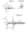
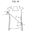
- Fig. 12 indicates another embodiment of the invention in which a support structure 101 of multistage construction is formed.
- Two bending means 61 and 62 are provided at the forward part of the guide member 5 and one bending means 61 is spaced from the other one 62 by an optional distance I.
- the latter 62 is provided with an aperture 62a through which the tubular member 81 only can penetrate as shown in Fig. 13.
- the structure of the bending means 62 is like that of the holder 6b mentioned in conjunction with Fig. 1.
- the inner tubular member 81 passes through the aperture 62a of the rear bending means 62 and the divided members of the forward part of the tubular. member 81 are outwardly bent by the foremost bending means 61.
- the divided members of the forward part of the outer tubular member 82 are outwardly bent by the rear bending means 62.
- a two-stage support structure 101 having its stages spaced by the distance I is formed within the furnace wall.
- the thickness of the sprayed refractory layer can be much thickened by a support member of two or more stages so that a repaired refractory wall of high dependability as well as durability can be attained.
- the repair work according to this invention is exceedingly effective.
- an opening 4 is provided by piercing or drilling at a part of the steel shell 1 where the refractory wall has been damaged, a guide member 5 is inserted via the opening 4 to be held thereat, a tubular member 8 having its forward end provided with a plurality of slits is fitted on the outside of the guide member 5, the guide member 5 together with the tubular member 8 are forced into the furnace, and the divided members of the forward end of the tubular member 8 are made to spread in the furnace in a flower petal manner to form a support structure 101 consisting of radially spread members.
- the monolithic refractory 12 is injected via the gap between the opening 4 and the tubular member 8, or the monolithic refractory 12 is sprayed via a nozzle introduced from an opening provided at the furnace top onto the spot to be repaired, so that a repaired refractory wall of high reliability can be obtained.
Landscapes
- Engineering & Computer Science (AREA)
- Chemical & Material Sciences (AREA)
- Manufacturing & Machinery (AREA)
- Materials Engineering (AREA)
- Metallurgy (AREA)
- Organic Chemistry (AREA)
- Furnace Housings, Linings, Walls, And Ceilings (AREA)
- Blast Furnaces (AREA)
Claims (7)
Applications Claiming Priority (4)
| Application Number | Priority Date | Filing Date | Title |
|---|---|---|---|
| JP12953981A JPS6017001B2 (ja) | 1981-08-19 | 1981-08-19 | 高炉炉壁の補修方法 |
| JP129539/81 | 1981-08-19 | ||
| JP92460/82 | 1982-05-31 | ||
| JP9246082A JPS6017002B2 (ja) | 1982-05-31 | 1982-05-31 | 高炉炉壁の補修方法 |
Publications (3)
| Publication Number | Publication Date |
|---|---|
| EP0072576A2 EP0072576A2 (fr) | 1983-02-23 |
| EP0072576A3 EP0072576A3 (en) | 1983-08-10 |
| EP0072576B1 true EP0072576B1 (fr) | 1986-07-23 |
Family
ID=26433879
Family Applications (1)
| Application Number | Title | Priority Date | Filing Date |
|---|---|---|---|
| EP82107547A Expired EP0072576B1 (fr) | 1981-08-19 | 1982-08-18 | Procédé pour réparer le garnissage réfractaire d'un haut fourneau |
Country Status (5)
| Country | Link |
|---|---|
| EP (1) | EP0072576B1 (fr) |
| KR (1) | KR850001534B1 (fr) |
| AU (1) | AU547322B2 (fr) |
| BR (1) | BR8204838A (fr) |
| DE (1) | DE3272143D1 (fr) |
Cited By (1)
| Publication number | Priority date | Publication date | Assignee | Title |
|---|---|---|---|---|
| RU2473491C1 (ru) * | 2011-11-11 | 2013-01-27 | Юлия Алексеевна Щепочкина | Арболитовая смесь |
Families Citing this family (1)
| Publication number | Priority date | Publication date | Assignee | Title |
|---|---|---|---|---|
| WO2017221118A1 (fr) * | 2016-06-21 | 2017-12-28 | Sabic Global Technologies B.V. | Réparation de revêtement réfractaire de fours et procédés associés |
Family Cites Families (2)
| Publication number | Priority date | Publication date | Assignee | Title |
|---|---|---|---|---|
| US3833334A (en) * | 1973-07-05 | 1974-09-03 | Combustion Eng | Apparatus for relining a bof vessel tap hole |
| FR2430583A1 (fr) * | 1978-07-07 | 1980-02-01 | Solmer | Procede et dispositif de regarnissage d'un four de fusion metallurgique |
-
1982
- 1982-08-17 AU AU87214/82A patent/AU547322B2/en not_active Ceased
- 1982-08-18 EP EP82107547A patent/EP0072576B1/fr not_active Expired
- 1982-08-18 DE DE8282107547T patent/DE3272143D1/de not_active Expired
- 1982-08-18 BR BR8204838A patent/BR8204838A/pt unknown
- 1982-08-19 KR KR8203737A patent/KR850001534B1/ko not_active Expired
Non-Patent Citations (2)
| Title |
|---|
| PATENT ABSTRACTS OF JAPAN, vol. 3, no. 100 (C-56), 24th August 1979, page 32C56 * |
| PATENT ABSTRACTS OF JAPAN, vol. 4, no. 22, (C-74), 23rd February 1980, page 16C74 * |
Cited By (1)
| Publication number | Priority date | Publication date | Assignee | Title |
|---|---|---|---|---|
| RU2473491C1 (ru) * | 2011-11-11 | 2013-01-27 | Юлия Алексеевна Щепочкина | Арболитовая смесь |
Also Published As
| Publication number | Publication date |
|---|---|
| EP0072576A3 (en) | 1983-08-10 |
| BR8204838A (pt) | 1983-08-02 |
| AU547322B2 (en) | 1985-10-17 |
| EP0072576A2 (fr) | 1983-02-23 |
| DE3272143D1 (en) | 1986-08-28 |
| AU8721482A (en) | 1983-02-24 |
| KR850001534B1 (ko) | 1985-10-16 |
| KR840001221A (ko) | 1984-03-28 |
Similar Documents
| Publication | Publication Date | Title |
|---|---|---|
| US4465648A (en) | Method for repairing refractory wall of furnace | |
| EP0072576B1 (fr) | Procédé pour réparer le garnissage réfractaire d'un haut fourneau | |
| US3495815A (en) | Outside change tuyere | |
| GB2043476A (en) | Gas distributor for fluidized beds | |
| EP0062986B1 (fr) | Lance pour réparer des récipients d'affinage | |
| JP3424144B2 (ja) | 転炉底吹き羽口の交換方法 | |
| JPH0689394B2 (ja) | 転炉の出鋼孔の補修用治具および出鋼孔の補修方法 | |
| JP2544719Y2 (ja) | 溶融金属容器のガス吹込みノズルの羽口構造 | |
| JPH05117738A (ja) | 転炉出鋼孔ライニングの補修に先立つ整形方法 | |
| JPH0140890B2 (fr) | ||
| JPS6028680Y2 (ja) | 溶融金属処理用ガス吹込みランス | |
| KR100477095B1 (ko) | 이단굴착바이트가 장착된 고로 출선구 굴착용 일발로드 장치 | |
| JPS5877511A (ja) | 高炉ステ−ブの剥離除去工法 | |
| JPS5846107Y2 (ja) | モルタル圧入孔 | |
| JPS5837951Y2 (ja) | ガス吹き込みパイプ | |
| JP2523061Y2 (ja) | 真空脱ガス設備用浸漬管における内巻き煉瓦脱落防止構造 | |
| JPS622237B2 (fr) | ||
| JPS57171605A (en) | Blowing-in method after intermediate relining of blast furnace | |
| JPS628487B2 (fr) | ||
| JPS626724B2 (fr) | ||
| JPS5881912A (ja) | 金属精錬炉羽口部の補修方法 | |
| JPS6136053B2 (fr) | ||
| SU985564A1 (ru) | Способ удалени из трубной доски теплообменной трубы и устройство дл его осуществлени | |
| JPS59129711A (ja) | 転炉底吹羽口の補修方法 | |
| JPS59179705A (ja) | 高炉炉底部の保護方法 |
Legal Events
| Date | Code | Title | Description |
|---|---|---|---|
| PUAI | Public reference made under article 153(3) epc to a published international application that has entered the european phase |
Free format text: ORIGINAL CODE: 0009012 |
|
| AK | Designated contracting states |
Designated state(s): DE FR GB IT |
|
| PUAL | Search report despatched |
Free format text: ORIGINAL CODE: 0009013 |
|
| 17P | Request for examination filed |
Effective date: 19830408 |
|
| AK | Designated contracting states |
Designated state(s): DE FR GB IT |
|
| ITF | It: translation for a ep patent filed | ||
| GRAA | (expected) grant |
Free format text: ORIGINAL CODE: 0009210 |
|
| AK | Designated contracting states |
Kind code of ref document: B1 Designated state(s): DE FR GB IT |
|
| ET | Fr: translation filed | ||
| REF | Corresponds to: |
Ref document number: 3272143 Country of ref document: DE Date of ref document: 19860828 |
|
| PLBE | No opposition filed within time limit |
Free format text: ORIGINAL CODE: 0009261 |
|
| STAA | Information on the status of an ep patent application or granted ep patent |
Free format text: STATUS: NO OPPOSITION FILED WITHIN TIME LIMIT |
|
| 26N | No opposition filed | ||
| PG25 | Lapsed in a contracting state [announced via postgrant information from national office to epo] |
Ref country code: GB Effective date: 19890818 |
|
| GBPC | Gb: european patent ceased through non-payment of renewal fee | ||
| PG25 | Lapsed in a contracting state [announced via postgrant information from national office to epo] |
Ref country code: FR Effective date: 19900427 |
|
| PG25 | Lapsed in a contracting state [announced via postgrant information from national office to epo] |
Ref country code: DE Effective date: 19900501 |
|
| REG | Reference to a national code |
Ref country code: FR Ref legal event code: ST |