EP0073892A1 - Raccord pour tubes isolants avec nervures périphériques - Google Patents
Raccord pour tubes isolants avec nervures périphériques Download PDFInfo
- Publication number
- EP0073892A1 EP0073892A1 EP82105897A EP82105897A EP0073892A1 EP 0073892 A1 EP0073892 A1 EP 0073892A1 EP 82105897 A EP82105897 A EP 82105897A EP 82105897 A EP82105897 A EP 82105897A EP 0073892 A1 EP0073892 A1 EP 0073892A1
- Authority
- EP
- European Patent Office
- Prior art keywords
- ribs
- securing element
- receptacle
- recess
- insulating tube
- Prior art date
- Legal status (The legal status is an assumption and is not a legal conclusion. Google has not performed a legal analysis and makes no representation as to the accuracy of the status listed.)
- Granted
Links
- 210000002445 nipple Anatomy 0.000 claims abstract description 26
- 238000007789 sealing Methods 0.000 claims description 5
- 230000004323 axial length Effects 0.000 claims description 2
- 230000037431 insertion Effects 0.000 abstract 1
- 238000003780 insertion Methods 0.000 abstract 1
- 239000011324 bead Substances 0.000 description 11
- 210000002105 tongue Anatomy 0.000 description 7
- 238000000926 separation method Methods 0.000 description 2
- 230000007704 transition Effects 0.000 description 2
- 230000015572 biosynthetic process Effects 0.000 description 1
- 230000000881 depressing effect Effects 0.000 description 1
- 230000003993 interaction Effects 0.000 description 1
- 238000012423 maintenance Methods 0.000 description 1
Images

Classifications
-
- F—MECHANICAL ENGINEERING; LIGHTING; HEATING; WEAPONS; BLASTING
- F16—ENGINEERING ELEMENTS AND UNITS; GENERAL MEASURES FOR PRODUCING AND MAINTAINING EFFECTIVE FUNCTIONING OF MACHINES OR INSTALLATIONS; THERMAL INSULATION IN GENERAL
- F16L—PIPES; JOINTS OR FITTINGS FOR PIPES; SUPPORTS FOR PIPES, CABLES OR PROTECTIVE TUBING; MEANS FOR THERMAL INSULATION IN GENERAL
- F16L37/00—Couplings of the quick-acting type
- F16L37/08—Couplings of the quick-acting type in which the connection between abutting or axially overlapping ends is maintained by locking members
- F16L37/12—Couplings of the quick-acting type in which the connection between abutting or axially overlapping ends is maintained by locking members using hooks, pawls, or other movable or insertable locking members
- F16L37/14—Joints secured by inserting between mating surfaces an element, e.g. a piece of wire, a pin, a chain
- F16L37/142—Joints secured by inserting between mating surfaces an element, e.g. a piece of wire, a pin, a chain where the securing element is inserted tangentially
- F16L37/146—Joints secured by inserting between mating surfaces an element, e.g. a piece of wire, a pin, a chain where the securing element is inserted tangentially the securing element being a rigid pin, screw or the like
-
- H—ELECTRICITY
- H02—GENERATION; CONVERSION OR DISTRIBUTION OF ELECTRIC POWER
- H02G—INSTALLATION OF ELECTRIC CABLES OR LINES, OR OF COMBINED OPTICAL AND ELECTRIC CABLES OR LINES
- H02G3/00—Installations of electric cables or lines or protective tubing therefor in or on buildings, equivalent structures or vehicles
- H02G3/02—Details
- H02G3/06—Joints for connecting lengths of protective tubing or channels, to each other or to casings, e.g. to distribution boxes; Ensuring electrical continuity in the joint
- H02G3/0616—Joints for connecting tubing to casing
- H02G3/0691—Fixing tubing to casing by auxiliary means co-operating with indentations of the tubing, e.g. with tubing-convolutions
-
- Y—GENERAL TAGGING OF NEW TECHNOLOGICAL DEVELOPMENTS; GENERAL TAGGING OF CROSS-SECTIONAL TECHNOLOGIES SPANNING OVER SEVERAL SECTIONS OF THE IPC; TECHNICAL SUBJECTS COVERED BY FORMER USPC CROSS-REFERENCE ART COLLECTIONS [XRACs] AND DIGESTS
- Y10—TECHNICAL SUBJECTS COVERED BY FORMER USPC
- Y10S—TECHNICAL SUBJECTS COVERED BY FORMER USPC CROSS-REFERENCE ART COLLECTIONS [XRACs] AND DIGESTS
- Y10S285/00—Pipe joints or couplings
- Y10S285/903—Corrugated
-
- Y—GENERAL TAGGING OF NEW TECHNOLOGICAL DEVELOPMENTS; GENERAL TAGGING OF CROSS-SECTIONAL TECHNOLOGIES SPANNING OVER SEVERAL SECTIONS OF THE IPC; TECHNICAL SUBJECTS COVERED BY FORMER USPC CROSS-REFERENCE ART COLLECTIONS [XRACs] AND DIGESTS
- Y10—TECHNICAL SUBJECTS COVERED BY FORMER USPC
- Y10S—TECHNICAL SUBJECTS COVERED BY FORMER USPC CROSS-REFERENCE ART COLLECTIONS [XRACs] AND DIGESTS
- Y10S285/00—Pipe joints or couplings
- Y10S285/921—Snap-fit
Definitions
- the invention relates to a connection nipple for circumferentially ribbed insulating pipes.
- the relatively thin-walled insulating tubes which are known to be used to hold electrical cables, must be provided with a nipple for connection to electrical devices, which has a threaded connector on one end for fastening to the housing wall of the device and the other end a receiving connector for the end of the insulating tube.
- nipples usually made of plastic, should enable a connection to the insulating tube that can no longer be detached without tools, which was previously only possible with relatively great effort.
- the present invention now aims to provide a nipple of the type mentioned, which enables the connection to the circumferentially finned insulating tube by simple manipulations and without tools, while the separation of the nipple from the tube cannot be accomplished without suitable tools.
- the nipple according to the invention which has an internally offset pipe section, which has a threaded connector on one end and a receiving connector for the insulating tube on the other, characterized in that a securing element is held in a wall recess of the receiving connector, which securing element has at least one for engagement in a circumferential channel of the insulating tube has a certain protrusion, and which can be pressed by hand into an operative position in which its protrusion protrudes radially into the socket bore and is held by force-locking or positive locking that can only be released by means of a tool.
- the securing element which is expediently made of plastic as well as the pipe section, can be designed as a push-button or spring arm which can be pressed in radially and is sunk in its operative position in the socket wall; slides which can be pressed tangentially into recesses of the connecting piece can also be provided as a securing element.
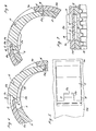
- the receptacle of the pipe section (the threaded connector is not shown) is designated 1 and provided with an outer bead la in its longitudinal central region.
- a recess 2 for example having a roughly square or circular outline, is provided;
- a radial bore 3 is provided through the nozzle wall.
- the location of the groove base is one designated by socket 1 circumferentially ribbed insulating tube indicated at 5.
- the transition from the recess 2 into the radial bore 3 is somewhat narrowed by a protruding lip 3a.
- a pressure plate 6 of the securing element which in its inactive position projects into the recess 2 by about half its height, is provided with a bolt 7 which engages under the lip 3a with a collar 7a and ends in a pin 8.
- the pin 8 lies completely within the wall thickness of the socket 1.
- Circumferential cams 6a or ribs which previously prevented the pressure plate 6 from falling into the recess 2, act as clamping members which make it impossible to remove the pressure plate 6 from the recess 2 by hand.
- the pin 8 is pressed into the circumferential groove of the insulating tube lying underneath, as a result of which this is perfectly prevented from axially separating from the insulating tube and nipple.
- this securing element designed as a push button could also be provided with a plurality of pins 8 carried by bolts 7 arranged on the pressure plate 6, each of which can engage in a circumferential groove of the insulating tube.
- the pipe section of the nipple has, in addition to a threaded connector (not shown), a receiving connector 10 with a circumferential bead 10a.
- Bead 10a and socket 10 each have a rectangular recess 11a and 11 in plan.
- a web 12 spanning the socket wall is formed on one circumferential end of the recesses and a stepped tongue 13 also overlapping the socket wall is formed on the other circumferential end of the recesses.
- the boundary wall of the recess 11 lying in the region of the web 12 is offset in the radial direction with the formation of an undercut 14.
- This pressure section 15b has a radially inner nose 16 which engages under the tongue 13 of the bead 10a and to which a ramp 17a with a step 17b adjoins; radially on the outside, the pressure section 15b has two edge tongues 18 which overlap the tongue 13 of the bead 10a and are separated by a cutout located in the region of the nose 16.
- the radial thickness of the pressure section 15b corresponds to the radial thickness of the bead and connecting piece wall.
- the inside of the pressure section 15b of the securing arm 15 is provided with two (there could also be several) extending in the circumferential direction of the connecting piece and the width and height of the circumferential grooves of the circumferentially ribbed insulating tube 19 to be accommodated in the connecting piece 10a (FIG. 7). provided adapted ribs 20.
- FIGS. 4, 6 and 7 The mode of operation of the securing element provided with the two ribs 20 is shown in FIGS. 4, 6 and 7 easily recognizable.
- the ribs 20 lie completely outside the clear width of the connector 10, so that the appropriate insulating tube 19 can be inserted without hindrance.
- the securing element 15 is pivoted inward about its bearing point formed by the undercut 14, so that the ribs 20 can engage in the grooves of the insulating tube 19 underneath.
- the ramp 17a slides under the tongue 13 until the latter rests on the shoulder 17b and thus prevents the securing element from swinging up again (FIG. 6). Only by placing a tool in the gap 18a between the bead 10a and the tongue 18 could the securing element 15 be released from its operative position secured by the interaction of the tongue 13 and the shoulder 17b.
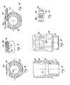
- FIG. 8-13 Another example is shown in Figs. 8-13.
- the socket piece 30 provided with a hexagon of the other end having a threaded socket 31 is provided with a tangential recess 32 which is connected in the middle to the bore of the socket piece 30 and is additionally open to the outside through a wall opening 32a.
- the recess 32 is designed in such a way that it cuts the inner bore of the socket 30 by the radial depth of the grooves of the insulating tube 33 (FIG. 9) provided for receiving it.
- an open circumferential groove 34 is created after the receptacle, in which, as indicated in FIG.
- a sealing ring 35 is supported, against which the insulating tube 33 can rest.
- the securing element is in this case a plastic slide 36.
- This slide 36 the underside of which is provided with three longitudinal ribs 37, fits into the recess 32 of the receptacle 30.
- a protruding cam 38 on the upper side of the slide makes it somewhat more difficult to insert the slide 36 into the recess 32 (FIG. 10), but thanks to the elasticity of the plastic it is easily possible by hand.
- the three ribs 37 of the slide 36 are also adjusted in height, width and mutual distance to the corresponding dimensions of the insulating tube 33, so that the inserted insulating tube is properly secured against axial separation from the nipple after the slide 36 has been inserted.
- the cam 38 which lies in the operative position in the opening 32a when the slide 36 is pushed in, prevents the slide from being removed by hand.
- the cam 38 is provided with an incision 38a, on which a tool, for example a screwdriver, can be attached; it is thus possible to push the slider 36 out of the recess 32 despite the protruding cam 38.
- an elastic sealing ring 35 is provided, as mentioned.
- the axial length of this ring is chosen so that when the insulating tube is pushed against the sealing ring 35, the circumferential grooves of the insulating tube are axially offset, for example by half the groove width, with respect to the position of the ribs 37 of the locking slide 36 to be used; by correspondingly pushing the tube inward against the elastically flexible sealing ring 35, the circumferential grooves of the tube can be inserted into their for the engagement of the ribs 20 of the Slider 36 are brought to the correct position.
- the slide 36 used not only secures the insulating tube in the nipple, but thus also ensures the maintenance of a tight connection between the insulating tube and the nipple.
Landscapes
- Engineering & Computer Science (AREA)
- General Engineering & Computer Science (AREA)
- Mechanical Engineering (AREA)
- Architecture (AREA)
- Civil Engineering (AREA)
- Structural Engineering (AREA)
- Quick-Acting Or Multi-Walled Pipe Joints (AREA)
- Lining Or Joining Of Plastics Or The Like (AREA)
- Processes Specially Adapted For Manufacturing Cables (AREA)
Priority Applications (1)
| Application Number | Priority Date | Filing Date | Title |
|---|---|---|---|
| AT82105897T ATE13347T1 (de) | 1981-09-07 | 1982-07-02 | Anschlussnippel fuer umfangsgerippte isolierrohre. |
Applications Claiming Priority (2)
| Application Number | Priority Date | Filing Date | Title |
|---|---|---|---|
| CH5748/81A CH652471A5 (de) | 1981-09-07 | 1981-09-07 | Anschlussnippel fuer umfangsgerippte isolierrohre. |
| CH5748/81 | 1981-09-07 |
Publications (2)
| Publication Number | Publication Date |
|---|---|
| EP0073892A1 true EP0073892A1 (fr) | 1983-03-16 |
| EP0073892B1 EP0073892B1 (fr) | 1985-05-15 |
Family
ID=4298685
Family Applications (1)
| Application Number | Title | Priority Date | Filing Date |
|---|---|---|---|
| EP82105897A Expired EP0073892B1 (fr) | 1981-09-07 | 1982-07-02 | Raccord pour tubes isolants avec nervures périphériques |
Country Status (7)
| Country | Link |
|---|---|
| US (1) | US4513998A (fr) |
| EP (1) | EP0073892B1 (fr) |
| AT (1) | ATE13347T1 (fr) |
| CA (1) | CA1184219A (fr) |
| CH (1) | CH652471A5 (fr) |
| DE (1) | DE3263523D1 (fr) |
| DK (1) | DK362382A (fr) |
Cited By (12)
| Publication number | Priority date | Publication date | Assignee | Title |
|---|---|---|---|---|
| US4575132A (en) * | 1984-05-31 | 1986-03-11 | Commander Electrical Materials, Inc. | Conduit connector wedge type |
| FR2586827A1 (fr) * | 1985-09-05 | 1987-03-06 | Lignes Telegraph Telephon | Dispositif pour la mise a la masse rapide d'un cable, tel qu'un cable optique. |
| GB2204187A (en) * | 1987-04-28 | 1988-11-02 | Kitagawa Ind Co Ltd | Connector fitting for a corrugated tube |
| GB2222228A (en) * | 1988-07-22 | 1990-02-28 | Oliver Engineering Limited | Valves |
| EP0392908A1 (fr) * | 1989-04-13 | 1990-10-17 | Societe Industrielle De Boulay, S.I.B.-A.D.R. | Raccord pour tuyauteries |
| NL1001273C2 (nl) * | 1995-09-22 | 1997-03-25 | Applied Power Inc | Vergrendeling voor een fluïduminsteekverbinding. |
| WO1998016772A1 (fr) * | 1996-10-14 | 1998-04-23 | Masco Corporation Of Indiana | Systeme de raccordement d'un appareil hydraulique a un element externe |
| GB2349188A (en) * | 1999-03-10 | 2000-10-25 | Colin George Burley | Connection for corrugated or ribbed pipes |
| GB2350656A (en) * | 1999-04-07 | 2000-12-06 | Polypipe Plc | Apparatus for connecting a conduit with a corrugated outer surface to another element |
| US6199920B1 (en) * | 1995-10-28 | 2001-03-13 | Interflex S.A. | Connecting piece for profiled pipes, profiled nipples, corrugated tubes or the like elongate articles |
| WO2022200597A1 (fr) * | 2021-03-26 | 2022-09-29 | Abb Schweiz Ag | Bague d'usure |
| US20230141677A1 (en) * | 2020-04-03 | 2023-05-11 | Endress+Hauser Wetzer Gmbh+Co. Kg | Thermometer for cryogenic applications |
Families Citing this family (8)
| Publication number | Priority date | Publication date | Assignee | Title |
|---|---|---|---|---|
| CA1272499A (fr) * | 1986-02-06 | 1990-08-07 | Commander Electrical Materials, Inc. | Raccord pour tubes ondules |
| US4836580A (en) * | 1988-03-01 | 1989-06-06 | Scepter Manufacturing Company Limited | Conduit connector |
| DE4216518A1 (de) * | 1992-05-19 | 1993-11-25 | United Carr Gmbh Trw | Klemmverbindung aus Kunststoff |
| BE1008705A3 (fr) * | 1994-09-23 | 1996-07-02 | Polva Pipelife Bv | Raccord de fixation pour un tube annele. |
| GB2315529A (en) * | 1996-07-24 | 1998-02-04 | Artform Int Ltd | Pipe connector with tangential retainer |
| GB0202305D0 (en) * | 2002-02-01 | 2002-03-20 | Smiths Group Plc | Pipe couplings |
| IL167905A (en) * | 2005-04-07 | 2008-06-05 | Israel Aerospace Ind Ltd | Structure coupler and coupler therefor |
| CA2686364A1 (fr) * | 2008-12-05 | 2010-06-05 | Plastiflex Canada Inc. | Raccordement sous vide |
Citations (2)
| Publication number | Priority date | Publication date | Assignee | Title |
|---|---|---|---|---|
| GB191112860A (en) * | 1911-05-29 | 1912-03-07 | Barton & Sons Ltd | An Improvement in Fittings for Electrical Conduits. |
| AT335001B (de) * | 1975-02-03 | 1977-02-25 | Goeransson Bengt S | Kupplungseinrichtung |
Family Cites Families (4)
| Publication number | Priority date | Publication date | Assignee | Title |
|---|---|---|---|---|
| GB191200081A (en) * | 1912-01-01 | 1912-11-14 | Frederick John Whiting | An Improved Joint for the Metallic Coverings of Insulated Electric Wires. |
| US1383303A (en) * | 1919-03-20 | 1921-07-05 | Grabler Mfg Company | Coupling |
| DE2908337C2 (de) * | 1979-03-03 | 1982-11-18 | PMA Elektro AG, 8623 Wetzikon | Anschlußarmatur für flexible Wellschläuche |
| US4423892A (en) * | 1980-10-29 | 1984-01-03 | Bartholomew Donald D | Swivelable quick connector assembly |
-
1981
- 1981-09-07 CH CH5748/81A patent/CH652471A5/de not_active IP Right Cessation
-
1982
- 1982-07-02 AT AT82105897T patent/ATE13347T1/de not_active IP Right Cessation
- 1982-07-02 EP EP82105897A patent/EP0073892B1/fr not_active Expired
- 1982-07-02 DE DE8282105897T patent/DE3263523D1/de not_active Expired
- 1982-08-12 DK DK362382A patent/DK362382A/da not_active Application Discontinuation
- 1982-08-13 US US06/407,733 patent/US4513998A/en not_active Expired - Fee Related
- 1982-08-18 CA CA000409712A patent/CA1184219A/fr not_active Expired
Patent Citations (2)
| Publication number | Priority date | Publication date | Assignee | Title |
|---|---|---|---|---|
| GB191112860A (en) * | 1911-05-29 | 1912-03-07 | Barton & Sons Ltd | An Improvement in Fittings for Electrical Conduits. |
| AT335001B (de) * | 1975-02-03 | 1977-02-25 | Goeransson Bengt S | Kupplungseinrichtung |
Cited By (17)
| Publication number | Priority date | Publication date | Assignee | Title |
|---|---|---|---|---|
| US4575132A (en) * | 1984-05-31 | 1986-03-11 | Commander Electrical Materials, Inc. | Conduit connector wedge type |
| FR2586827A1 (fr) * | 1985-09-05 | 1987-03-06 | Lignes Telegraph Telephon | Dispositif pour la mise a la masse rapide d'un cable, tel qu'un cable optique. |
| GB2204187A (en) * | 1987-04-28 | 1988-11-02 | Kitagawa Ind Co Ltd | Connector fitting for a corrugated tube |
| GB2204187B (en) * | 1987-04-28 | 1991-01-09 | Kitagawa Ind Co Ltd | Connector fitting for a corrugated tube |
| GB2222228A (en) * | 1988-07-22 | 1990-02-28 | Oliver Engineering Limited | Valves |
| EP0392908A1 (fr) * | 1989-04-13 | 1990-10-17 | Societe Industrielle De Boulay, S.I.B.-A.D.R. | Raccord pour tuyauteries |
| FR2645942A1 (fr) * | 1989-04-13 | 1990-10-19 | Sib Adr | Raccord pour tuyauterie |
| US5765879A (en) * | 1995-09-22 | 1998-06-16 | Applied Power Inc. | Locking arrangement for a fluid insertion connection |
| NL1001273C2 (nl) * | 1995-09-22 | 1997-03-25 | Applied Power Inc | Vergrendeling voor een fluïduminsteekverbinding. |
| US6199920B1 (en) * | 1995-10-28 | 2001-03-13 | Interflex S.A. | Connecting piece for profiled pipes, profiled nipples, corrugated tubes or the like elongate articles |
| WO1998016772A1 (fr) * | 1996-10-14 | 1998-04-23 | Masco Corporation Of Indiana | Systeme de raccordement d'un appareil hydraulique a un element externe |
| GB2349188A (en) * | 1999-03-10 | 2000-10-25 | Colin George Burley | Connection for corrugated or ribbed pipes |
| GB2350656A (en) * | 1999-04-07 | 2000-12-06 | Polypipe Plc | Apparatus for connecting a conduit with a corrugated outer surface to another element |
| GB2350656B (en) * | 1999-04-07 | 2003-04-23 | Polypipe Plc | Conduits |
| US20230141677A1 (en) * | 2020-04-03 | 2023-05-11 | Endress+Hauser Wetzer Gmbh+Co. Kg | Thermometer for cryogenic applications |
| WO2022200597A1 (fr) * | 2021-03-26 | 2022-09-29 | Abb Schweiz Ag | Bague d'usure |
| US12601429B2 (en) | 2021-03-26 | 2026-04-14 | Abb Schweiz Ag | Wear ring |
Also Published As
| Publication number | Publication date |
|---|---|
| US4513998A (en) | 1985-04-30 |
| CA1184219A (fr) | 1985-03-19 |
| CH652471A5 (de) | 1985-11-15 |
| ATE13347T1 (de) | 1985-06-15 |
| DK362382A (da) | 1983-03-08 |
| EP0073892B1 (fr) | 1985-05-15 |
| DE3263523D1 (en) | 1985-06-20 |
Similar Documents
| Publication | Publication Date | Title |
|---|---|---|
| EP0073892B1 (fr) | Raccord pour tubes isolants avec nervures périphériques | |
| DE68903750T2 (de) | Vorrichtung zur befestigung eines durch eine wand zu fuehrenden teiles. | |
| EP0086900B1 (fr) | Raccord de connexion en matière plastique pour tuyaux isolés et nervurés sur leur pourtour | |
| DE3890614C2 (de) | Wellrohr-Verbinder | |
| DE69209919T2 (de) | Anzeigevorrichtung für eine Schnellverschlusskupplung | |
| DE4334529C2 (de) | Verbindungsvorrichtung für ein flexibles Wellrohr | |
| DE69422418T2 (de) | Schnellkupplung mit einem integrierten entriegelungselement | |
| DE3224798C2 (de) | Verbindungsvorrichtung für zylindrische oder rohrförmige Körper | |
| EP0057916A2 (fr) | Dispositif de fixation des manches aux ustensiles, en particulier ustensiles domestiques et de jardin | |
| DE2042938A1 (de) | Rohranschluß, insbesondere fur Steig leitungen von Unterwasser Bohrungen | |
| DE2901306A1 (de) | Schnelltrennduese | |
| EP0059877A1 (fr) | Accouplement pour tuyaux à pression | |
| DE19540279A1 (de) | Anschlußstück für Profilrohre, Profilstutzen, Wellschläuche oder dergleichen Stränge | |
| DE8915932U1 (de) | Rohrverbinder | |
| DE19830586A1 (de) | Tränkeventil | |
| DE3248154C1 (de) | Elektrische Steckverbindung | |
| EP1457607B1 (fr) | Armature sanitaire comportant un dispositif pour fixer une conduite | |
| DE3604213A1 (de) | Kabelverschraubung | |
| DE3522390A1 (de) | Anschlussdose fuer eine wasserarmatur | |
| DE1603699A1 (de) | Werkzeug fuer elektrische Verbinder | |
| DE4239250A1 (de) | Einsteckkupplung für die Verbindung von zwei Kunststoffrohren | |
| EP0727850A2 (fr) | Dispositif pour le positionnement d'un composant électrique ou électronique dans une boîte | |
| EP0455972B1 (fr) | Dispositif support pour l'accouplement simultané de plusieurs raccords parallèles pour fluide | |
| DE1675178A1 (de) | Rohrkupplung | |
| DE102021102585A1 (de) | Steckverbindungen zum lösbaren Verbinden von Leitungen und System umfassend eine solche Steckverbindung |
Legal Events
| Date | Code | Title | Description |
|---|---|---|---|
| PUAI | Public reference made under article 153(3) epc to a published international application that has entered the european phase |
Free format text: ORIGINAL CODE: 0009012 |
|
| AK | Designated contracting states |
Designated state(s): AT BE DE FR GB IT NL SE |
|
| 17P | Request for examination filed |
Effective date: 19830826 |
|
| ITF | It: translation for a ep patent filed | ||
| GRAA | (expected) grant |
Free format text: ORIGINAL CODE: 0009210 |
|
| AK | Designated contracting states |
Designated state(s): AT BE DE FR GB IT NL SE |
|
| REF | Corresponds to: |
Ref document number: 13347 Country of ref document: AT Date of ref document: 19850615 Kind code of ref document: T |
|
| REF | Corresponds to: |
Ref document number: 3263523 Country of ref document: DE Date of ref document: 19850620 |
|
| ET | Fr: translation filed | ||
| PLBE | No opposition filed within time limit |
Free format text: ORIGINAL CODE: 0009261 |
|
| STAA | Information on the status of an ep patent application or granted ep patent |
Free format text: STATUS: NO OPPOSITION FILED WITHIN TIME LIMIT |
|
| 26N | No opposition filed | ||
| PGFP | Annual fee paid to national office [announced via postgrant information from national office to epo] |
Ref country code: AT Payment date: 19860703 Year of fee payment: 5 |
|
| PGFP | Annual fee paid to national office [announced via postgrant information from national office to epo] |
Ref country code: NL Payment date: 19860731 Year of fee payment: 5 |
|
| PG25 | Lapsed in a contracting state [announced via postgrant information from national office to epo] |
Ref country code: AT Effective date: 19870702 |
|
| PG25 | Lapsed in a contracting state [announced via postgrant information from national office to epo] |
Ref country code: SE Effective date: 19870703 |
|
| BERE | Be: lapsed |
Owner name: GROSSAUER ALFRED Effective date: 19870731 |
|
| PG25 | Lapsed in a contracting state [announced via postgrant information from national office to epo] |
Ref country code: NL Effective date: 19880201 |
|
| NLV4 | Nl: lapsed or anulled due to non-payment of the annual fee | ||
| PG25 | Lapsed in a contracting state [announced via postgrant information from national office to epo] |
Ref country code: FR Free format text: LAPSE BECAUSE OF NON-PAYMENT OF DUE FEES Effective date: 19880331 |
|
| PG25 | Lapsed in a contracting state [announced via postgrant information from national office to epo] |
Ref country code: DE Effective date: 19880401 |
|
| GBPC | Gb: european patent ceased through non-payment of renewal fee | ||
| REG | Reference to a national code |
Ref country code: FR Ref legal event code: ST |
|
| PG25 | Lapsed in a contracting state [announced via postgrant information from national office to epo] |
Ref country code: GB Free format text: LAPSE BECAUSE OF NON-PAYMENT OF DUE FEES Effective date: 19881121 |
|
| PG25 | Lapsed in a contracting state [announced via postgrant information from national office to epo] |
Ref country code: BE Effective date: 19890731 |
|
| EUG | Se: european patent has lapsed |
Ref document number: 82105897.1 Effective date: 19880901 |