EP0074113A2 - Appareil de commande pour moteur à combustion interne - Google Patents
Appareil de commande pour moteur à combustion interne Download PDFInfo
- Publication number
- EP0074113A2 EP0074113A2 EP82108221A EP82108221A EP0074113A2 EP 0074113 A2 EP0074113 A2 EP 0074113A2 EP 82108221 A EP82108221 A EP 82108221A EP 82108221 A EP82108221 A EP 82108221A EP 0074113 A2 EP0074113 A2 EP 0074113A2
- Authority
- EP
- European Patent Office
- Prior art keywords
- rotation speed
- engine
- warming
- throttle valve
- signal
- Prior art date
- Legal status (The legal status is an assumption and is not a legal conclusion. Google has not performed a legal analysis and makes no representation as to the accuracy of the status listed.)
- Granted
Links
- 238000002485 combustion reaction Methods 0.000 title claims abstract description 11
- 239000000446 fuel Substances 0.000 claims description 59
- 230000001133 acceleration Effects 0.000 claims description 19
- 230000001502 supplementing effect Effects 0.000 claims description 18
- 230000007423 decrease Effects 0.000 claims description 6
- 230000004044 response Effects 0.000 claims description 6
- 238000010792 warming Methods 0.000 claims description 3
- XLYOFNOQVPJJNP-UHFFFAOYSA-N water Substances O XLYOFNOQVPJJNP-UHFFFAOYSA-N 0.000 claims description 2
- 238000001816 cooling Methods 0.000 claims 1
- 239000000498 cooling water Substances 0.000 abstract description 11
- VHYFNPMBLIVWCW-UHFFFAOYSA-N 4-Dimethylaminopyridine Chemical compound CN(C)C1=CC=NC=C1 VHYFNPMBLIVWCW-UHFFFAOYSA-N 0.000 description 22
- 230000001276 controlling effect Effects 0.000 description 9
- 238000000034 method Methods 0.000 description 6
- 230000000994 depressogenic effect Effects 0.000 description 3
- 230000003247 decreasing effect Effects 0.000 description 2
- 238000010586 diagram Methods 0.000 description 2
- 239000007789 gas Substances 0.000 description 2
- 239000000203 mixture Substances 0.000 description 2
- QVGXLLKOCUKJST-UHFFFAOYSA-N atomic oxygen Chemical compound [O] QVGXLLKOCUKJST-UHFFFAOYSA-N 0.000 description 1
- 230000000694 effects Effects 0.000 description 1
- 230000006870 function Effects 0.000 description 1
- 239000001301 oxygen Substances 0.000 description 1
- 229910052760 oxygen Inorganic materials 0.000 description 1
- 230000001105 regulatory effect Effects 0.000 description 1
- 239000007858 starting material Substances 0.000 description 1
- 239000013589 supplement Substances 0.000 description 1
- 238000011144 upstream manufacturing Methods 0.000 description 1
Images





Classifications
-
- F—MECHANICAL ENGINEERING; LIGHTING; HEATING; WEAPONS; BLASTING
- F02—COMBUSTION ENGINES; HOT-GAS OR COMBUSTION-PRODUCT ENGINE PLANTS
- F02D—CONTROLLING COMBUSTION ENGINES
- F02D31/00—Use of speed-sensing governors to control combustion engines, not otherwise provided for
- F02D31/001—Electric control of rotation speed
- F02D31/002—Electric control of rotation speed controlling air supply
- F02D31/003—Electric control of rotation speed controlling air supply for idle speed control
- F02D31/004—Electric control of rotation speed controlling air supply for idle speed control by controlling a throttle stop
-
- F—MECHANICAL ENGINEERING; LIGHTING; HEATING; WEAPONS; BLASTING
- F02—COMBUSTION ENGINES; HOT-GAS OR COMBUSTION-PRODUCT ENGINE PLANTS
- F02D—CONTROLLING COMBUSTION ENGINES
- F02D41/00—Electrical control of supply of combustible mixture or its constituents
- F02D41/24—Electrical control of supply of combustible mixture or its constituents characterised by the use of digital means
- F02D41/26—Electrical control of supply of combustible mixture or its constituents characterised by the use of digital means using computer, e.g. microprocessor
- F02D41/263—Electrical control of supply of combustible mixture or its constituents characterised by the use of digital means using computer, e.g. microprocessor the program execution being modifiable by physical parameters
-
- Y—GENERAL TAGGING OF NEW TECHNOLOGICAL DEVELOPMENTS; GENERAL TAGGING OF CROSS-SECTIONAL TECHNOLOGIES SPANNING OVER SEVERAL SECTIONS OF THE IPC; TECHNICAL SUBJECTS COVERED BY FORMER USPC CROSS-REFERENCE ART COLLECTIONS [XRACs] AND DIGESTS
- Y02—TECHNOLOGIES OR APPLICATIONS FOR MITIGATION OR ADAPTATION AGAINST CLIMATE CHANGE
- Y02T—CLIMATE CHANGE MITIGATION TECHNOLOGIES RELATED TO TRANSPORTATION
- Y02T10/00—Road transport of goods or passengers
- Y02T10/10—Internal combustion engine [ICE] based vehicles
- Y02T10/40—Engine management systems
Definitions
- This invention relates to an apparatus for electronically controlling the quantity of air and the quantity and quality of the air-fuel mixture supplied to an internal combustion engine.
- United States Patent No. 3,964,457 proposes a technique for controlling an internal combustion engine, in which, in order to rotate the internal combustion engine at an appropriate rotation speed in its warming-up stage, the actual rotation speed (rpm) of the engine is compared with the rotation speed (rpm) corresponding to the temperature of engine cooling water to find the error therebetween, and the quantity of air supplied to the engine is regulated on the-basis of the error.
- the desired warming-up rotation speed is set at a high level so as to shorten the length of time required for warming up the engine and has such a characteristic that the higher the temperature of engine cooling water, it becomes lower along a gradient.
- Another object of the present invention is to provide an apparatus of the kind above described in which means are provided to suppress generation of the CO component to a minimum when the throttle valve is opened under the condition in which the vehicle is not driven and the engine is being merely warmed up.
- the control apparatus is featured by the fact that a first desired warming-up rotation speed corresponding to the temperature of engine cooling water and a second desired warming-up rotation speed lower than the first desired warming-up rotation speed are previously set, and the rotation speed of the internal combustion engine is so controlled that the engine rotates at the first desired warming-up rotation speed when the throttle valve is not opened even a single time during warming-up and at the second desired warming-up rotation speed when the throttle valve is opened once and is then closed during wraming-up.
- the present invention is also featured by the fact that the quantity of fuel is increased for acceleration when the throttle valve is opened during warming-up to drive the vehicle, but the increase in the quantity of fuel for acceleration is not done when the vehicle is not driven although the throttle valve is opened.
- FIG. 1 shows generally the structure of a preferred embodiment of the electronic engine control apparatus according to the present invention.
- a carburetor 3 is provided in an intake pipe 2 of an internal combustion engine 1.
- a main fuel control solenoid 7 and a slow fuel control solenoid 8 are associated with the carburetor 3.
- the former solenoid 7 is energized for controlling the main jet, and the latter solenoid 8 is energized for controlling the slow air bleed.
- Two other solenoids 10 and 11 are also associated with the carburetor 3.
- the former solenoid 10 is energized for increasing the quantity of fuel for starting the engine, and the latter solenoid 11 is energized for increasing the quantity of fuel for accelerating the engine.
- a throttle switch 12 and a throttle opening sensor 13 are associated with a throttle valve (not shown) disposed in the carburetor 3.
- the throttle switch 12 senses whether the throttle valve is full closed or not, and the throttle opening sensor 13 senses the opening of the throttle valve.
- An air cleaner 4 is disposed upstream of the carburetor 3 to supply clean air to the carburetor 3.
- the air cleaner 4 is provided with an intake air temperature sensor 18 sensing the temperature of intake air.
- a pressure sensor 14 for sensing the internal pressure of the intake pipe 2 is provided on the intake pipe 2.
- An exhaust pipe 5 extends from the engine 1, and an 02 sensor 17 for sensing oxygen in the engine exhaust gases thereby detecting the air-fuel ratio is provided on the exhaust pipe 5.
- the engine 1 is provided with a crank angle sensor 16 for sensing the engine crank angle, a water temperature sensor 15 for sensing the temperature of engine cooling water, a rotation speed sensor 19 for sensing the rotation speed of the engine 1, and a vehicle speed sensor 20 for sensing the speed of the vehicle.
- the output signals from all of these sensors 12 to 20 are applied to a control unit 6 including a microcomputer therein, and, on the basis of the input signals from the sensors, the control unit 6 energizes the actuators such as the main fuel control solenoid 7, slow fuel control solenoid 8, starting fuel increasing solenoid 10 and accelerating fuel increasing solenoid 11 associated with the carburetor 3 thereby controlling the engine 1.
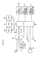
- FIG . 2 is a block diagram showing the structure of the control unit 6 shown in FI G . 1.
- the control unit 6 includes, as its fundamental elements, a microprocessing unit (abbreviated hereinafter as an M PU) 30 making arithmetic and logical processing, a memory element (abbreviated hereinafter as an ROM) 32 storing a control program and fixed data, a readable and writable memory element (abbreviated hereinafter as an RAM) 31, and a control part 33 including an input/output interface.
- MPU 30, ROM 32, RAM 31 and control part 33 are connected to each other by an address bus, a data bus and control lines. Signals applied to the control unit 6 are classified into analog signals and digital signals.
- Analog input signals include the output signals from the intake air temperature sensor 18, cooling water temperature sensor 15, throttle opening sensor 13, 0 2 sensor 17 and pressure sensor 14. These signals are applied to a multiplexer (abbreviated hereinafter as an MPX) 34.
- the MPX 34 has the function of selectively applying the analog signals to an analog-digital converter (abbreviated hereinafter as an A/D converter) 35 under control of a control signal applied from the control part 33 under command of the MPU 30. As a result, the A/D converter 35 is actuated to convert its analog input signal into a digital signal which is applied to the control part 33 of the control unit 6.
- Digital input signals include the output signal from the throttle switch 12 sensing the full closure of the throttle valve and the output signal from the starter 36. These digital input signals are applied to the control part 33 of the control unit 6.
- the crank angle sensor 16 generates two kinds of pulse signals, that is, a pulse signal generated each time the crankshaft rotates through a predetermined crank angle of, for example, 180° and a pulse signal generated each time the crankshaft rotates through another predetermined rotation angle of, for example, 1°. These two kinds of pulse signals are applied to the control part 33 of the control unit 6 as digital data indicative of the rotation speed (rpm) of the engine 1.
- the MPU 30 makes necessary computation according to the control program stored in the ROM 32, and the resultant data are applied to the control part 33, so that the control unit 6 applies necessary output signals to.the elements including the main fuel control solenoid 7, slow fuel control solenoid 8, starting fuel increasing solenoid 10 and/or'accelerating fuel increasing solenoid 11 for selectively energizing the same.
- FIG. 3 shows the air-fuel ratio relative to the on-duty of the main fuel control solenoid 7 and shows also the air-fuel ratio relative to the on-duty of the slow fuel control solenoid 8.
- the system including the main fuel control solenoid 7 controls the fuel, and, therefore, the air-fuel ratio decreases with the increase in the on-duty factor.
- the system including the slow fuel control solenoid 8 controls the air bleed, and, therefore, the air-fuel ratio increases with the increases in the on-duty factor.
- the fuel-air ratio can be controlled to be set at the stoichiometric value of 14.7 when the on-duty factors are controlled to be 50%.
- the air-fuel ratio can be controlled to be set at the stoichiometric value by controlling the main and slow fuel control valves when the operating parameters are fixed.
- FIG. 4 shows a map representing the on-duty factor relative to various values of the operating parameters including the vacuum in the intake pipe 2 and the rotation speed of the engine 1. Such a control map is stored in the ROM 32.
- the on-duty factor required for supplying the air-fuel mixture of the stoichiometric air-fuel ratio can be determined on the basis of the sensed engine rotation speed and intake vacuum.
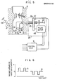
- the throttle valve 40 is disposed downstream of the venturi of the carburetor 3. Associated with this throttle valve 40 are a throttle actuating lever 41 arranged for interlocking movement with the throttle valve 40 and a throttle return lever 43 pivoted to the throttle valve 40 by a pivot pin 42 for making rocking movement around the pivot pin 42.
- a return spring 44 is anchored at one end thereof to one or free end of the throttle return lever 43 so as to normally bias the throttle return lever 43 in one direction.
- the free end of the throttle actuating lever 41 is engaged by one end of a storke shaft 45 which makes threaded engagement at its threaded portion with a reduction gear 46 mounted on the shaft of a pulse motor 48.
- An idling sensing switch 47 is disposed adjacent to the reduction gear 46 so that.idling is sensed when the reduction gear 46 is brought into contact with the idling sensing switch 47.
- a spring 49 is anchored at one end thereof to the other end of the stroke shaft 45, that is, the end remote from the end making engagement with the throttle actuating lever 41, so as to normally bias the stroke shaft 45 in a direction shown by the arrow B.
- the pulse motor 48, spring 49, idling sensing switch 47, stroke shaft 45 and reduction gear 46 constitute the throttle actuator 21.
- the throttle valve 40 is normally biased clockwise as viewed in FIG. 5 by the force of the return spring 44 in the direction of the arrow A. Unless the accelerator pedal is depressed, the throttle actuating lever 41 presses against the stroke shaft 45, and the idling sensing switch 47 is sensing that the engine 1 is idling. When now the accelerator pedal is depressed, the throttle actuating lever 41 turns counter-clockwise in F IG. 5, and the stroke shaft 45 is biased in the direction of the arrow B by the force of the spring 49. As a result, the reduction gear 46 moves away from the idling sensing switch 47, so that the idling sensing switch 47 senses that the engine is not idling.
- the desired idling rotation speed determined by the position of the stroke shaft 45 is determined by the pulse motor 48. The above operation is carried out under control of the control unit 6. Now, with the rotation of the motor 48, the gear 46 rotates, while the stroke shaft 45 does not rotate.
- a pulse voltage waveform as shown in FIG. 6 is applied to the pulse motor 48 in the throttle actuator 21 shown in FIG. 5.
- the symbols A and B designate a normal-rotation pulse signal and a reverse-rotation pulse signal applied to the pulse motor 48 respectively.
- the rotation speed of the engine increases linearly with the increase in the number of pulses and decreases linearly with the decrease in the number of pulses.
- the linear speed increase in response to the application of the normal-rotation pulse signal is represented by A in FIG.- 7
- the linear speed decrease in response to the application of the reverse-rotation pulse signal is represented by B in FIG. 7.
- FIG. 8 shows the relation between the pulse occurrence period and the error AN of the engine rotation speed N.
- the symbols A and B in FIG. 8 designate the relation when the normal-rotation pulse signal and reverse-rotation pulse signal are applied to the pulse motor 48 respectively.
- FIG. 9 shows two desired idling rotation speeds relative to the temperature T W of engine cooling water in the embodiment of the present invention.
- the characteristic curve N setO represents the desired idling rotation speed when the engine is warmed up without depression of the accelerator pedal even for a short time
- the characteristic curve N setl represents the desired idling rotation speed when the throttle valve 40 is opened once and the closed for revving up during warming-up, or when the vehicle is not driven under the warming-up condition.
- FIG. 11 shows the process of rotation speed control according to the present invention.
- FIG. 10 illustrates how the rotation speed of the engine varies when the throttle valve is opened at time t 0 and closed at time t l .
- the data N set0 and N set1 are read out from the ROM 32 and stored in the RAM 31 at time t 0 , and the flag indicating that the rotation speed is to be N set0 before depression of the accelerator pedal is set.
- the number of pulses corresponding to the value (N set0 - N set1 ) is computed, and the reverse-rotation pulse signal including the computed number of pulses of short period which is different from the pulse period characteristic shown in FIG. 8 is applied to the pulse motor 48.
- FIG. 11 shows the characteristic curves of such coefficients K A , K B and K C respectively representing coefficients in a state of acceleration, a state other than acceleration and deceleration, and a state of deceleration.
- the signal indicative of the value obtained by multiplication of the on-duty map data D MAP determined from FIG. 4 by one of these coefficients K A , K B and K C is applied to the main fuel control solenoid 7, slow fuel control solenoid 8, starting fuel increasing solenoid 10 and accelerating fuel increasing solenoid 11.
- FIG. 14 shows the variation of the on-duty factor of the signal applied to the slow and main fuel control solenoids 8 and 7 when the engine rotating at the idling rotation speed is revved up.
- the fuel quantity is increased to supplement the acceleration as shown by the broken curves in FIG. 14, and the result is that a large quantity of CO is geneated whenever the engine is revved up during idling, as shown in FIG. 12.
- such a large quantity of CO is not generated since the fuel quantity is not increased for supplementing the acceleration even when the accelerator pedal is depressed at the vehicle speed of 0 Km/h, as seen in FIG. 13.
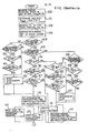
- the program is run at predetermined time intervals of, for example, 10 msec.
- step 100 the rotation speed N of the engine 1 and the vacuum V C in the intake pipe 2 are measured.
- step 101 the corresponding map duty D MAP is read out from the map shown in FIG. 4.
- step 102 the temperature T W of engine cooling water is measured to select the idling rotation speeds N set0 , N set1 and the coefficients K A , K B , K C .
- step 103 the differential value dV /dt of the vacuum V c in the intake pipe is computed.
- step 104 judgment is made as to whether or not the flag indicative of acceleration supplementing is set at "1".
- step 105 judgment is made in step 105 as to whether or not the flag indicative of deceleration supplementing is set at "1".
- step 106 judgment is made in step 106 as to whether or not the period of time required for deceleration supplementing has elapsed.
- step 108 judgment is made in step 108 as to whether or not the relation ⁇ a holds, where a shows a predetermined opening rate of the throttle valve.
- step 107 judgment is made in step 108 as to whether or not the relation ⁇ a holds, where a shows a predetermined opening rate of the throttle valve.
- step 111 When the result of judgment in step 104 proves that the flag indicative of acceleration supplementing is set at "1", judgment is made in step 111 as to whether or not the acceleration supplementing period of time has elapsed. When the result of judgment in step 111 is "yes”, the flag indicative of acceleration is reset in step 112. On the other hand, when the result of judgment in step 111 is "no”, judgment is made in step 113 as to whether or not the relation ⁇ B holds, where shows a predetermined closing rate of the throttle valve. When the result of judgment in step 113 is "yes”, step 112 is followed. On the other hand, when the result of judgment in step 113 is "no", judgment is made in step 114 as to whether or not the idling sensing switch 47 is in its off position.
- step 112 is followed.
- step 115 is followed in which judgment dV is made as to whether or not the relation ⁇ a holds.
- judgment dV is made as to whether or not the relation ⁇ a holds.
- step 116 judges whether or not the idling sensing switch 47 is in its off position.
- step 117 judges whether or not the relation vehicle speed Vp > 0 Km/h holds.
- step 119 is followed in which judgment is made as to whether or not the relation - ⁇ ⁇ holds.
- judgment is made in step 120 as to whether or not the idling sensing switch 47 is in its on position.
- step 121 is followed.
- judgment is made in step 122 as to whether or not the relation Vp > 0 Km/h holds.
- step 120 when the result of judgment in step 120 proves that the idling sensing swtich 47 is not turned on, step 121 is followed.
- step 110 is followed in which the deceleration supplementing period of time is set, the duty D DUT KC x D MAP is computed, and the flag indicative of deceleration is set.
- step 118 K A x D MAP computed in step 118 is applied in step 123 to the main fuel control solenoid 7 and slow fuel control solenoid 8 for the acceleration supplementing period of time and is also applied in step 147 to the accelerating fuel increasing solenoid 11.
- step 124 judges whether or not the idling sensing switch 47 is in its on position.
- step 127 judgment is made in step 127 as to whether or not the flag indicative of storage of N set0 and N setl is set at "1".
- step 131 is followed.
- step 128 is followed in which N set0 and N set1 are stored in the RAM 31.
- step 129 the flag indicative of storage of N set0 and N se1 is set at "1".
- step 130 the flag indicative of whether N is represented by N set0 or N setl immediately before turning-off of the idling sensing switch 47 is set.
- step 131 the throttle actuator 21 is deenergized to complete the program.
- step 134 judgment is made in step 134 as to whether or not the required pulse application completion flag indicative of the control by the computed number of the reverse-rotation pulses corresponding to the value of (N set0 - Nset1 ) selected u p to that time is set at "1".
- step 144 is followed.
- step 135 judgment is made in step 135 as to whether or not the flag indicative of application of the required pulses is set at "1".
- step 136 When the result of judgment in step 135 proves that the.flag is set at "1", judgment is made in step 136 as to whether or not the engine rotation speed N is lower than or equal to N setl .
- step 138 is followed.
- step 137 On the other hand, when the result of judgment in step 136 proves that the relation N ⁇ N tl does not hold, judgment is made in step 137 as to whether or not application of the required pulses has been completed.
- the result of judgment in step 137 proves that application of the pulses has been completed, the flag indicative of complete application of the required pulses is set at "1" in step 138, and the throttle actuator 21 is deenergized in step 131.
- step 142 is followed.
- step 139 judges whether or not N set0 has been selected up to then for the control.
- the result of judgment in step 139 is "yes”
- the number of required pulses is computed on the basis of the previous value of (N set0 N setl ) in step 140, and teh flag indicative of application of the required pulses is set at "1" in step 141.
- a short pulse period different from the pulse period characteristic shown in FIG. 8 is set in step 142, and the reverse-rotation pulse signal is applied to the pulse motor 48 in step 143.
- step 144 judges whether or not the relation N ⁇ N set0 (or N setl ) holds.
- the pulse period B in the pulse period characteristic shown in FIG. 8 is set in step 145 to apply the reverse-rotation pulse signal to the pulse motor 48.
- the pulse period A in the pulse period characteristic shown in FIG. 8 is set in step 146 to apply the normal-rotation pulse signal to the pulse motor 48.
- the rotation speed error AN N N set0 is computed in step 126, and whether or not the relation N ⁇ N set0 holds is judged in step 144. Then, in step 145 or 146, the pulse period B or A corresponding to the value of ⁇ N is set.
- the procedure including the steps 139 to 143 is carried out immediately after the closure of the throttle valve, and a short pulse period different from the characteristic shown in FIG. 8 is set to apply the reverse-rotation pulse signal of short period to the pulse motor 48.
- the rotation speed error ⁇ N N - N setl is computed in step 126, and whether or not the relation N ⁇ N setl holds is judged in step 144. Then, the pulse period B or A corresponding to the value of ⁇ N is set in step 145 or 146.
Landscapes
- Engineering & Computer Science (AREA)
- Chemical & Material Sciences (AREA)
- Combustion & Propulsion (AREA)
- Mechanical Engineering (AREA)
- General Engineering & Computer Science (AREA)
- Computer Hardware Design (AREA)
- Microelectronics & Electronic Packaging (AREA)
- Electrical Control Of Air Or Fuel Supplied To Internal-Combustion Engine (AREA)
- Control Of Throttle Valves Provided In The Intake System Or In The Exhaust System (AREA)
Applications Claiming Priority (2)
| Application Number | Priority Date | Filing Date | Title |
|---|---|---|---|
| JP141018/81 | 1981-09-09 | ||
| JP56141018A JPS5844249A (ja) | 1981-09-09 | 1981-09-09 | アイドル回転数制御装置 |
Publications (3)
| Publication Number | Publication Date |
|---|---|
| EP0074113A2 true EP0074113A2 (fr) | 1983-03-16 |
| EP0074113A3 EP0074113A3 (en) | 1984-03-28 |
| EP0074113B1 EP0074113B1 (fr) | 1986-09-10 |
Family
ID=15282277
Family Applications (1)
| Application Number | Title | Priority Date | Filing Date |
|---|---|---|---|
| EP82108221A Expired EP0074113B1 (fr) | 1981-09-09 | 1982-09-07 | Appareil de commande pour moteur à combustion interne |
Country Status (4)
| Country | Link |
|---|---|
| US (1) | US4469064A (fr) |
| EP (1) | EP0074113B1 (fr) |
| JP (1) | JPS5844249A (fr) |
| DE (1) | DE3273196D1 (fr) |
Cited By (1)
| Publication number | Priority date | Publication date | Assignee | Title |
|---|---|---|---|---|
| EP0661430A1 (fr) * | 1992-07-20 | 1995-07-05 | Hyundai Motor Company | Dispositif et méthode de commande d'augmentation de la vitesse de ralenti d'un moteur |
Families Citing this family (10)
| Publication number | Priority date | Publication date | Assignee | Title |
|---|---|---|---|---|
| JPS58172446A (ja) * | 1982-04-02 | 1983-10-11 | Honda Motor Co Ltd | 内燃機関の作動状態制御装置 |
| US4619237A (en) * | 1983-05-25 | 1986-10-28 | Auslander David M | Engine cold starting |
| JPS603448A (ja) * | 1983-06-20 | 1985-01-09 | Honda Motor Co Ltd | 内燃エンジンの作動状態制御方法 |
| FI68916C (fi) * | 1983-12-30 | 1985-11-11 | Kone Oy | Foerfarande foer att ladda ett instrument med kyvetter samt enyvettfoerpackning |
| JPS61129446A (ja) * | 1984-11-28 | 1986-06-17 | Fuji Heavy Ind Ltd | アイドル回転数制御装置 |
| JPS623147A (ja) * | 1985-06-28 | 1987-01-09 | Honda Motor Co Ltd | 内燃機関のアイドル回転数制御装置 |
| JPH0255520A (ja) * | 1988-08-16 | 1990-02-23 | Fujitsu Denso Ltd | スイッチング・レギュレータの負荷短絡保護回路 |
| JPH0275739A (ja) * | 1988-09-08 | 1990-03-15 | Mitsubishi Electric Corp | 機関のアイドル調整方法 |
| JP2922752B2 (ja) * | 1993-07-29 | 1999-07-26 | 三菱電機株式会社 | ステップモータの駆動制御装置 |
| US11733691B2 (en) * | 2020-11-03 | 2023-08-22 | Ford Global Technologies, Llc | Remote controlled engine revving |
Family Cites Families (7)
| Publication number | Priority date | Publication date | Assignee | Title |
|---|---|---|---|---|
| JPS5727299B2 (fr) * | 1974-01-26 | 1982-06-09 | ||
| US3964457A (en) * | 1974-06-14 | 1976-06-22 | The Bendix Corporation | Closed loop fast idle control system |
| US4191137A (en) * | 1976-11-04 | 1980-03-04 | Lucas Industries Limited | Electronic fuel injection control for an internal combustion engine |
| US4240145A (en) * | 1977-12-01 | 1980-12-16 | Nissan Motor Company, Limited | Closed loop controlled auxiliary air delivery system for internal combustion engine |
| CA1127273A (fr) * | 1978-10-23 | 1982-07-06 | Edwin D. Des Lauriers | Regulateur de ralenti a correction asymetrique des rapports pour moteur de vehicule automobile |
| JPS5752650A (en) * | 1980-09-17 | 1982-03-29 | Toyota Motor Corp | Fuel cut-off control method for internal combustion engine |
| JPS57131834A (en) * | 1981-02-10 | 1982-08-14 | Automob Antipollut & Saf Res Center | Engine speed control device |
-
1981
- 1981-09-09 JP JP56141018A patent/JPS5844249A/ja active Granted
-
1982
- 1982-09-07 DE DE8282108221T patent/DE3273196D1/de not_active Expired
- 1982-09-07 EP EP82108221A patent/EP0074113B1/fr not_active Expired
- 1982-09-08 US US06/416,044 patent/US4469064A/en not_active Expired - Fee Related
Cited By (1)
| Publication number | Priority date | Publication date | Assignee | Title |
|---|---|---|---|---|
| EP0661430A1 (fr) * | 1992-07-20 | 1995-07-05 | Hyundai Motor Company | Dispositif et méthode de commande d'augmentation de la vitesse de ralenti d'un moteur |
Also Published As
| Publication number | Publication date |
|---|---|
| JPS5844249A (ja) | 1983-03-15 |
| DE3273196D1 (en) | 1986-10-16 |
| JPS6336410B2 (fr) | 1988-07-20 |
| EP0074113B1 (fr) | 1986-09-10 |
| EP0074113A3 (en) | 1984-03-28 |
| US4469064A (en) | 1984-09-04 |
Similar Documents
| Publication | Publication Date | Title |
|---|---|---|
| US4691677A (en) | Throttle valve control system for internal combustion engine | |
| US4739483A (en) | Automatic transmission control system for an automobile | |
| US4581924A (en) | Method of detecting opening of a throttle valve in a fully closed position in an internal combustion engine | |
| KR880002075B1 (ko) | 스파아크 점화 내연기관용 전자(電子)조절식 연료 분사장치 | |
| US4385602A (en) | Rotational speed control device during idling of engine | |
| US4462378A (en) | Control apparatus for an internal combustion engine having a carburetor | |
| US4399792A (en) | Air/fuel ratio control system for internal combustion engines, having engine warming-up detecting means | |
| US4469064A (en) | Apparatus for controlling internal combustion engine | |
| EP0979934B1 (fr) | Unité de commande électronique de papillon d'admission | |
| JPH0625545B2 (ja) | 内燃機関の電子スロツトル制御装置 | |
| US4938195A (en) | Atmospheric pressure detecting device for engine control | |
| US4531490A (en) | Idling speed feedback control method having fail-safe function for abnormalities in functioning of crank angle position-detecting system of an internal combustion engine | |
| US5195497A (en) | Method for detecting fuel blending ratio | |
| KR900000579A (ko) | 내연기관의 드로틀 제어장치 | |
| US4474151A (en) | Engine revolution speed control device | |
| US4938199A (en) | Method for controlling the air-fuel ratio in vehicle internal combustion engines | |
| EP0100063B1 (fr) | Appareil et méthode de commande de la quantité d'air au démarrage de moteur | |
| GB2136606A (en) | Idling rpm feedback control method for internal combustion engines | |
| US5197451A (en) | Method for detecting fuel blending ratio | |
| US4753209A (en) | Air-fuel ratio control system for internal combustion engines capable of controlling air-fuel ratio in accordance with degree of warming-up of the engines | |
| EP0110312B1 (fr) | Méthode de commande de moteur | |
| GB2148549A (en) | Method of controlling operating amounts of operation control means for an internal combustion engine | |
| JPH06272580A (ja) | 内燃機関のバルブタイミングの制御方法 | |
| JPS639092B2 (fr) | ||
| EP0113529B1 (fr) | Procédé de commande de marche pour moteurs pas-à-pas |
Legal Events
| Date | Code | Title | Description |
|---|---|---|---|
| PUAI | Public reference made under article 153(3) epc to a published international application that has entered the european phase |
Free format text: ORIGINAL CODE: 0009012 |
|
| AK | Designated contracting states |
Designated state(s): CH DE FR GB IT LI NL SE |
|
| PUAL | Search report despatched |
Free format text: ORIGINAL CODE: 0009013 |
|
| AK | Designated contracting states |
Designated state(s): CH DE FR GB IT LI NL SE |
|
| 17P | Request for examination filed |
Effective date: 19840330 |
|
| GRAA | (expected) grant |
Free format text: ORIGINAL CODE: 0009210 |
|
| RBV | Designated contracting states (corrected) |
Designated state(s): DE FR GB |
|
| AK | Designated contracting states |
Kind code of ref document: B1 Designated state(s): DE FR GB |
|
| REF | Corresponds to: |
Ref document number: 3273196 Country of ref document: DE Date of ref document: 19861016 |
|
| ET | Fr: translation filed | ||
| PLBE | No opposition filed within time limit |
Free format text: ORIGINAL CODE: 0009261 |
|
| STAA | Information on the status of an ep patent application or granted ep patent |
Free format text: STATUS: NO OPPOSITION FILED WITHIN TIME LIMIT |
|
| 26N | No opposition filed | ||
| PGFP | Annual fee paid to national office [announced via postgrant information from national office to epo] |
Ref country code: FR Payment date: 19920615 Year of fee payment: 11 |
|
| PGFP | Annual fee paid to national office [announced via postgrant information from national office to epo] |
Ref country code: GB Payment date: 19920624 Year of fee payment: 11 |
|
| PGFP | Annual fee paid to national office [announced via postgrant information from national office to epo] |
Ref country code: DE Payment date: 19920930 Year of fee payment: 11 |
|
| PG25 | Lapsed in a contracting state [announced via postgrant information from national office to epo] |
Ref country code: GB Effective date: 19930907 |
|
| GBPC | Gb: european patent ceased through non-payment of renewal fee |
Effective date: 19930907 |
|
| PG25 | Lapsed in a contracting state [announced via postgrant information from national office to epo] |
Ref country code: FR Free format text: LAPSE BECAUSE OF NON-PAYMENT OF DUE FEES Effective date: 19940531 |
|
| PG25 | Lapsed in a contracting state [announced via postgrant information from national office to epo] |
Ref country code: DE Effective date: 19940601 |
|
| REG | Reference to a national code |
Ref country code: FR Ref legal event code: ST |