EP0075353A1 - Procédé et dispositif pour la détermination de substances en solution à l'aide d'un guide d'ondes optique - Google Patents
Procédé et dispositif pour la détermination de substances en solution à l'aide d'un guide d'ondes optique Download PDFInfo
- Publication number
- EP0075353A1 EP0075353A1 EP82201107A EP82201107A EP0075353A1 EP 0075353 A1 EP0075353 A1 EP 0075353A1 EP 82201107 A EP82201107 A EP 82201107A EP 82201107 A EP82201107 A EP 82201107A EP 0075353 A1 EP0075353 A1 EP 0075353A1
- Authority
- EP
- European Patent Office
- Prior art keywords
- analyte
- core
- wave
- reactant
- guide
- Prior art date
- Legal status (The legal status is an assumption and is not a legal conclusion. Google has not performed a legal analysis and makes no representation as to the accuracy of the status listed.)
- Granted
Links
- 230000003287 optical effect Effects 0.000 title claims abstract description 62
- 238000000034 method Methods 0.000 title claims description 64
- 239000012491 analyte Substances 0.000 claims abstract description 104
- 239000000376 reactant Substances 0.000 claims abstract description 49
- 230000035515 penetration Effects 0.000 claims abstract description 17
- 239000000463 material Substances 0.000 claims abstract description 5
- 239000012429 reaction media Substances 0.000 claims abstract description 5
- 239000000835 fiber Substances 0.000 claims description 103
- 238000006243 chemical reaction Methods 0.000 claims description 55
- 238000012360 testing method Methods 0.000 claims description 37
- 239000010408 film Substances 0.000 claims description 26
- 238000000576 coating method Methods 0.000 claims description 24
- 239000011248 coating agent Substances 0.000 claims description 21
- 238000010521 absorption reaction Methods 0.000 claims description 17
- 230000008859 change Effects 0.000 claims description 16
- 239000013307 optical fiber Substances 0.000 claims description 16
- 230000004048 modification Effects 0.000 claims description 15
- 238000012986 modification Methods 0.000 claims description 15
- 230000003993 interaction Effects 0.000 claims description 13
- 230000010287 polarization Effects 0.000 claims description 11
- 239000000700 radioactive tracer Substances 0.000 claims description 9
- 230000015572 biosynthetic process Effects 0.000 claims description 8
- 230000000694 effects Effects 0.000 claims description 5
- 239000010409 thin film Substances 0.000 claims description 5
- 230000007423 decrease Effects 0.000 claims description 4
- 230000036961 partial effect Effects 0.000 claims description 3
- 238000012545 processing Methods 0.000 claims description 3
- 102000036639 antigens Human genes 0.000 description 112
- 108091007433 antigens Proteins 0.000 description 112
- 239000000427 antigen Substances 0.000 description 108
- 239000000243 solution Substances 0.000 description 58
- 239000003153 chemical reaction reagent Substances 0.000 description 40
- 239000000523 sample Substances 0.000 description 40
- 238000003556 assay Methods 0.000 description 32
- 238000005259 measurement Methods 0.000 description 30
- 239000000047 product Substances 0.000 description 22
- 238000005253 cladding Methods 0.000 description 21
- 230000000875 corresponding effect Effects 0.000 description 20
- 239000011521 glass Substances 0.000 description 20
- 210000004027 cell Anatomy 0.000 description 19
- 230000035945 sensitivity Effects 0.000 description 14
- 238000004458 analytical method Methods 0.000 description 12
- 230000005284 excitation Effects 0.000 description 12
- 229940027941 immunoglobulin g Drugs 0.000 description 11
- 239000007788 liquid Substances 0.000 description 9
- 241000894007 species Species 0.000 description 9
- 230000008901 benefit Effects 0.000 description 8
- 239000000872 buffer Substances 0.000 description 8
- 239000007795 chemical reaction product Substances 0.000 description 8
- 238000005530 etching Methods 0.000 description 8
- 238000002474 experimental method Methods 0.000 description 8
- 102000004169 proteins and genes Human genes 0.000 description 8
- 108090000623 proteins and genes Proteins 0.000 description 8
- XLYOFNOQVPJJNP-UHFFFAOYSA-N water Substances O XLYOFNOQVPJJNP-UHFFFAOYSA-N 0.000 description 8
- 230000005540 biological transmission Effects 0.000 description 7
- 239000003599 detergent Substances 0.000 description 6
- 230000005684 electric field Effects 0.000 description 6
- 239000008363 phosphate buffer Substances 0.000 description 6
- 241000283973 Oryctolagus cuniculus Species 0.000 description 5
- 238000010586 diagram Methods 0.000 description 5
- 239000012153 distilled water Substances 0.000 description 5
- 238000009826 distribution Methods 0.000 description 5
- 238000011049 filling Methods 0.000 description 5
- 238000011065 in-situ storage Methods 0.000 description 5
- 230000008569 process Effects 0.000 description 5
- 230000004044 response Effects 0.000 description 5
- CSCPPACGZOOCGX-UHFFFAOYSA-N Acetone Chemical compound CC(C)=O CSCPPACGZOOCGX-UHFFFAOYSA-N 0.000 description 4
- 102000004190 Enzymes Human genes 0.000 description 4
- 108090000790 Enzymes Proteins 0.000 description 4
- FAPWRFPIFSIZLT-UHFFFAOYSA-M Sodium chloride Chemical compound [Na+].[Cl-] FAPWRFPIFSIZLT-UHFFFAOYSA-M 0.000 description 4
- 238000013459 approach Methods 0.000 description 4
- 230000001419 dependent effect Effects 0.000 description 4
- 238000001514 detection method Methods 0.000 description 4
- 238000010790 dilution Methods 0.000 description 4
- 239000012895 dilution Substances 0.000 description 4
- MHMNJMPURVTYEJ-UHFFFAOYSA-N fluorescein-5-isothiocyanate Chemical compound O1C(=O)C2=CC(N=C=S)=CC=C2C21C1=CC=C(O)C=C1OC1=CC(O)=CC=C21 MHMNJMPURVTYEJ-UHFFFAOYSA-N 0.000 description 4
- 230000006870 function Effects 0.000 description 4
- 238000003018 immunoassay Methods 0.000 description 4
- 239000000203 mixture Substances 0.000 description 4
- 238000000926 separation method Methods 0.000 description 4
- VYPSYNLAJGMNEJ-UHFFFAOYSA-N silicon dioxide Inorganic materials O=[Si]=O VYPSYNLAJGMNEJ-UHFFFAOYSA-N 0.000 description 4
- 108091003079 Bovine Serum Albumin Proteins 0.000 description 3
- 108060003951 Immunoglobulin Proteins 0.000 description 3
- QAOWNCQODCNURD-UHFFFAOYSA-N Sulfuric acid Chemical compound OS(O)(=O)=O QAOWNCQODCNURD-UHFFFAOYSA-N 0.000 description 3
- 230000000903 blocking effect Effects 0.000 description 3
- 210000004369 blood Anatomy 0.000 description 3
- 239000008280 blood Substances 0.000 description 3
- 229940098773 bovine serum albumin Drugs 0.000 description 3
- 239000004568 cement Substances 0.000 description 3
- 230000002860 competitive effect Effects 0.000 description 3
- 238000009792 diffusion process Methods 0.000 description 3
- 229920001971 elastomer Polymers 0.000 description 3
- 230000005672 electromagnetic field Effects 0.000 description 3
- 238000000572 ellipsometry Methods 0.000 description 3
- 229940088597 hormone Drugs 0.000 description 3
- 239000005556 hormone Substances 0.000 description 3
- 102000018358 immunoglobulin Human genes 0.000 description 3
- 238000001727 in vivo Methods 0.000 description 3
- 238000009304 pastoral farming Methods 0.000 description 3
- 239000004033 plastic Substances 0.000 description 3
- 229920003023 plastic Polymers 0.000 description 3
- 230000002285 radioactive effect Effects 0.000 description 3
- 239000002904 solvent Substances 0.000 description 3
- 239000000126 substance Substances 0.000 description 3
- 238000011282 treatment Methods 0.000 description 3
- LFQSCWFLJHTTHZ-UHFFFAOYSA-N Ethanol Chemical compound CCO LFQSCWFLJHTTHZ-UHFFFAOYSA-N 0.000 description 2
- KRHYYFGTRYWZRS-UHFFFAOYSA-N Fluorane Chemical compound F KRHYYFGTRYWZRS-UHFFFAOYSA-N 0.000 description 2
- 238000002835 absorbance Methods 0.000 description 2
- 230000009471 action Effects 0.000 description 2
- 239000007853 buffer solution Substances 0.000 description 2
- 239000003795 chemical substances by application Substances 0.000 description 2
- 238000004737 colorimetric analysis Methods 0.000 description 2
- 230000009918 complex formation Effects 0.000 description 2
- 150000001875 compounds Chemical class 0.000 description 2
- 230000002596 correlated effect Effects 0.000 description 2
- 230000008878 coupling Effects 0.000 description 2
- 238000010168 coupling process Methods 0.000 description 2
- 238000005859 coupling reaction Methods 0.000 description 2
- 238000000151 deposition Methods 0.000 description 2
- 239000003814 drug Substances 0.000 description 2
- GNBHRKFJIUUOQI-UHFFFAOYSA-N fluorescein Chemical compound O1C(=O)C2=CC=CC=C2C21C1=CC=C(O)C=C1OC1=CC(O)=CC=C21 GNBHRKFJIUUOQI-UHFFFAOYSA-N 0.000 description 2
- 230000001900 immune effect Effects 0.000 description 2
- 230000000984 immunochemical effect Effects 0.000 description 2
- 238000002347 injection Methods 0.000 description 2
- 239000007924 injection Substances 0.000 description 2
- NOESYZHRGYRDHS-UHFFFAOYSA-N insulin Chemical compound N1C(=O)C(NC(=O)C(CCC(N)=O)NC(=O)C(CCC(O)=O)NC(=O)C(C(C)C)NC(=O)C(NC(=O)CN)C(C)CC)CSSCC(C(NC(CO)C(=O)NC(CC(C)C)C(=O)NC(CC=2C=CC(O)=CC=2)C(=O)NC(CCC(N)=O)C(=O)NC(CC(C)C)C(=O)NC(CCC(O)=O)C(=O)NC(CC(N)=O)C(=O)NC(CC=2C=CC(O)=CC=2)C(=O)NC(CSSCC(NC(=O)C(C(C)C)NC(=O)C(CC(C)C)NC(=O)C(CC=2C=CC(O)=CC=2)NC(=O)C(CC(C)C)NC(=O)C(C)NC(=O)C(CCC(O)=O)NC(=O)C(C(C)C)NC(=O)C(CC(C)C)NC(=O)C(CC=2NC=NC=2)NC(=O)C(CO)NC(=O)CNC2=O)C(=O)NCC(=O)NC(CCC(O)=O)C(=O)NC(CCCNC(N)=N)C(=O)NCC(=O)NC(CC=3C=CC=CC=3)C(=O)NC(CC=3C=CC=CC=3)C(=O)NC(CC=3C=CC(O)=CC=3)C(=O)NC(C(C)O)C(=O)N3C(CCC3)C(=O)NC(CCCCN)C(=O)NC(C)C(O)=O)C(=O)NC(CC(N)=O)C(O)=O)=O)NC(=O)C(C(C)CC)NC(=O)C(CO)NC(=O)C(C(C)O)NC(=O)C1CSSCC2NC(=O)C(CC(C)C)NC(=O)C(NC(=O)C(CCC(N)=O)NC(=O)C(CC(N)=O)NC(=O)C(NC(=O)C(N)CC=1C=CC=CC=1)C(C)C)CC1=CN=CN1 NOESYZHRGYRDHS-UHFFFAOYSA-N 0.000 description 2
- 238000002372 labelling Methods 0.000 description 2
- 150000002605 large molecules Chemical class 0.000 description 2
- 229920002521 macromolecule Polymers 0.000 description 2
- 239000003960 organic solvent Substances 0.000 description 2
- 239000003973 paint Substances 0.000 description 2
- 239000002244 precipitate Substances 0.000 description 2
- 239000010453 quartz Substances 0.000 description 2
- 238000003127 radioimmunoassay Methods 0.000 description 2
- 230000002829 reductive effect Effects 0.000 description 2
- 230000002441 reversible effect Effects 0.000 description 2
- 239000012085 test solution Substances 0.000 description 2
- 241000380131 Ammophila arenaria Species 0.000 description 1
- 241000894006 Bacteria Species 0.000 description 1
- 241000424941 Canis lupus lupus Species 0.000 description 1
- WQZGKKKJIJFFOK-GASJEMHNSA-N Glucose Natural products OC[C@H]1OC(O)[C@H](O)[C@@H](O)[C@@H]1O WQZGKKKJIJFFOK-GASJEMHNSA-N 0.000 description 1
- 102000001554 Hemoglobins Human genes 0.000 description 1
- 108010054147 Hemoglobins Proteins 0.000 description 1
- 102000004877 Insulin Human genes 0.000 description 1
- 108090001061 Insulin Proteins 0.000 description 1
- VVQNEPGJFQJSBK-UHFFFAOYSA-N Methyl methacrylate Chemical compound COC(=O)C(C)=C VVQNEPGJFQJSBK-UHFFFAOYSA-N 0.000 description 1
- 101100400378 Mus musculus Marveld2 gene Proteins 0.000 description 1
- 229920005372 Plexiglas® Polymers 0.000 description 1
- 229920001213 Polysorbate 20 Polymers 0.000 description 1
- 239000004793 Polystyrene Substances 0.000 description 1
- 108010071390 Serum Albumin Proteins 0.000 description 1
- 102000007562 Serum Albumin Human genes 0.000 description 1
- 229910003074 TiCl4 Inorganic materials 0.000 description 1
- 241000700605 Viruses Species 0.000 description 1
- 239000002250 absorbent Substances 0.000 description 1
- 230000002745 absorbent Effects 0.000 description 1
- 238000000862 absorption spectrum Methods 0.000 description 1
- 230000003321 amplification Effects 0.000 description 1
- 239000000538 analytical sample Substances 0.000 description 1
- 239000007864 aqueous solution Substances 0.000 description 1
- 238000000149 argon plasma sintering Methods 0.000 description 1
- 238000001210 attenuated total reflectance infrared spectroscopy Methods 0.000 description 1
- 239000011324 bead Substances 0.000 description 1
- 230000006399 behavior Effects 0.000 description 1
- 230000000975 bioactive effect Effects 0.000 description 1
- 238000004166 bioassay Methods 0.000 description 1
- 230000008033 biological extinction Effects 0.000 description 1
- 239000012490 blank solution Substances 0.000 description 1
- 210000000601 blood cell Anatomy 0.000 description 1
- 230000005587 bubbling Effects 0.000 description 1
- 238000011088 calibration curve Methods 0.000 description 1
- 230000000711 cancerogenic effect Effects 0.000 description 1
- 238000005119 centrifugation Methods 0.000 description 1
- 239000013626 chemical specie Substances 0.000 description 1
- 238000004140 cleaning Methods 0.000 description 1
- 238000012875 competitive assay Methods 0.000 description 1
- 230000000295 complement effect Effects 0.000 description 1
- 239000011365 complex material Substances 0.000 description 1
- 238000010668 complexation reaction Methods 0.000 description 1
- 239000012141 concentrate Substances 0.000 description 1
- 239000000470 constituent Substances 0.000 description 1
- 230000009260 cross reactivity Effects 0.000 description 1
- 230000003247 decreasing effect Effects 0.000 description 1
- 230000008021 deposition Effects 0.000 description 1
- 238000013461 design Methods 0.000 description 1
- 238000003745 diagnosis Methods 0.000 description 1
- AHUXYBVKTIBBJW-UHFFFAOYSA-N dimethoxy(diphenyl)silane Chemical compound C=1C=CC=CC=1[Si](OC)(OC)C1=CC=CC=C1 AHUXYBVKTIBBJW-UHFFFAOYSA-N 0.000 description 1
- 238000006073 displacement reaction Methods 0.000 description 1
- 238000010494 dissociation reaction Methods 0.000 description 1
- 230000005593 dissociations Effects 0.000 description 1
- 229940079593 drug Drugs 0.000 description 1
- 238000001035 drying Methods 0.000 description 1
- 239000000428 dust Substances 0.000 description 1
- 238000011067 equilibration Methods 0.000 description 1
- 239000005329 float glass Substances 0.000 description 1
- 239000008103 glucose Substances 0.000 description 1
- 238000004442 gravimetric analysis Methods 0.000 description 1
- 239000011440 grout Substances 0.000 description 1
- 229940098197 human immunoglobulin g Drugs 0.000 description 1
- 230000002209 hydrophobic effect Effects 0.000 description 1
- 230000006872 improvement Effects 0.000 description 1
- 239000012535 impurity Substances 0.000 description 1
- 238000000338 in vitro Methods 0.000 description 1
- 239000004615 ingredient Substances 0.000 description 1
- 229940125396 insulin Drugs 0.000 description 1
- 230000002452 interceptive effect Effects 0.000 description 1
- 239000004816 latex Substances 0.000 description 1
- 229920000126 latex Polymers 0.000 description 1
- 230000000670 limiting effect Effects 0.000 description 1
- 238000011068 loading method Methods 0.000 description 1
- 230000000873 masking effect Effects 0.000 description 1
- 239000011159 matrix material Substances 0.000 description 1
- 230000007246 mechanism Effects 0.000 description 1
- 238000006386 neutralization reaction Methods 0.000 description 1
- 238000003199 nucleic acid amplification method Methods 0.000 description 1
- 238000005457 optimization Methods 0.000 description 1
- 239000002245 particle Substances 0.000 description 1
- 230000000149 penetrating effect Effects 0.000 description 1
- 238000005375 photometry Methods 0.000 description 1
- 229920000728 polyester Polymers 0.000 description 1
- 229920000642 polymer Polymers 0.000 description 1
- 239000000256 polyoxyethylene sorbitan monolaurate Substances 0.000 description 1
- 235000010486 polyoxyethylene sorbitan monolaurate Nutrition 0.000 description 1
- 229920002223 polystyrene Polymers 0.000 description 1
- 108090000765 processed proteins & peptides Proteins 0.000 description 1
- 102000004196 processed proteins & peptides Human genes 0.000 description 1
- 230000001681 protective effect Effects 0.000 description 1
- 239000012460 protein solution Substances 0.000 description 1
- 239000011541 reaction mixture Substances 0.000 description 1
- 230000009257 reactivity Effects 0.000 description 1
- 239000011347 resin Substances 0.000 description 1
- 229920005989 resin Polymers 0.000 description 1
- 230000000284 resting effect Effects 0.000 description 1
- 230000000717 retained effect Effects 0.000 description 1
- 238000012552 review Methods 0.000 description 1
- 229910052594 sapphire Inorganic materials 0.000 description 1
- 239000010980 sapphire Substances 0.000 description 1
- 229920006395 saturated elastomer Polymers 0.000 description 1
- 238000009738 saturating Methods 0.000 description 1
- 238000011896 sensitive detection Methods 0.000 description 1
- 229910052710 silicon Inorganic materials 0.000 description 1
- 239000010703 silicon Substances 0.000 description 1
- 239000000377 silicon dioxide Substances 0.000 description 1
- 229920002379 silicone rubber Polymers 0.000 description 1
- 239000004945 silicone rubber Substances 0.000 description 1
- 239000007787 solid Substances 0.000 description 1
- 238000000638 solvent extraction Methods 0.000 description 1
- 238000004611 spectroscopical analysis Methods 0.000 description 1
- 239000013589 supplement Substances 0.000 description 1
- XJDNKRIXUMDJCW-UHFFFAOYSA-J titanium tetrachloride Chemical compound Cl[Ti](Cl)(Cl)Cl XJDNKRIXUMDJCW-UHFFFAOYSA-J 0.000 description 1
- 238000004448 titration Methods 0.000 description 1
- 231100000331 toxic Toxicity 0.000 description 1
- 230000002588 toxic effect Effects 0.000 description 1
- 230000001131 transforming effect Effects 0.000 description 1
- 238000004879 turbidimetry Methods 0.000 description 1
- 230000000007 visual effect Effects 0.000 description 1
- 238000010792 warming Methods 0.000 description 1
- 238000005406 washing Methods 0.000 description 1
- 239000003643 water by type Substances 0.000 description 1
- 230000005428 wave function Effects 0.000 description 1
- 238000004804 winding Methods 0.000 description 1
Images


Classifications
-
- G—PHYSICS
- G01—MEASURING; TESTING
- G01N—INVESTIGATING OR ANALYSING MATERIALS BY DETERMINING THEIR CHEMICAL OR PHYSICAL PROPERTIES
- G01N21/00—Investigating or analysing materials by the use of optical means, i.e. using sub-millimetre waves, infrared, visible or ultraviolet light
- G01N21/62—Systems in which the material investigated is excited whereby it emits light or causes a change in wavelength of the incident light
- G01N21/63—Systems in which the material investigated is excited whereby it emits light or causes a change in wavelength of the incident light optically excited
- G01N21/64—Fluorescence; Phosphorescence
- G01N21/645—Specially adapted constructive features of fluorimeters
- G01N21/648—Specially adapted constructive features of fluorimeters using evanescent coupling or surface plasmon coupling for the excitation of fluorescence
-
- G—PHYSICS
- G01—MEASURING; TESTING
- G01N—INVESTIGATING OR ANALYSING MATERIALS BY DETERMINING THEIR CHEMICAL OR PHYSICAL PROPERTIES
- G01N21/00—Investigating or analysing materials by the use of optical means, i.e. using sub-millimetre waves, infrared, visible or ultraviolet light
- G01N21/62—Systems in which the material investigated is excited whereby it emits light or causes a change in wavelength of the incident light
- G01N21/63—Systems in which the material investigated is excited whereby it emits light or causes a change in wavelength of the incident light optically excited
- G01N21/64—Fluorescence; Phosphorescence
- G01N21/645—Specially adapted constructive features of fluorimeters
- G01N21/6452—Individual samples arranged in a regular 2D-array, e.g. multiwell plates
-
- G—PHYSICS
- G01—MEASURING; TESTING
- G01N—INVESTIGATING OR ANALYSING MATERIALS BY DETERMINING THEIR CHEMICAL OR PHYSICAL PROPERTIES
- G01N21/00—Investigating or analysing materials by the use of optical means, i.e. using sub-millimetre waves, infrared, visible or ultraviolet light
- G01N21/75—Systems in which material is subjected to a chemical reaction, the progress or the result of the reaction being investigated
- G01N21/77—Systems in which material is subjected to a chemical reaction, the progress or the result of the reaction being investigated by observing the effect on a chemical indicator
- G01N21/7703—Systems in which material is subjected to a chemical reaction, the progress or the result of the reaction being investigated by observing the effect on a chemical indicator using reagent-clad optical fibres or optical waveguides
-
- G—PHYSICS
- G01—MEASURING; TESTING
- G01N—INVESTIGATING OR ANALYSING MATERIALS BY DETERMINING THEIR CHEMICAL OR PHYSICAL PROPERTIES
- G01N33/00—Investigating or analysing materials by specific methods not covered by groups G01N1/00 - G01N31/00
- G01N33/48—Biological material, e.g. blood, urine; Haemocytometers
- G01N33/50—Chemical analysis of biological material, e.g. blood, urine; Testing involving biospecific ligand binding methods; Immunological testing
- G01N33/53—Immunoassay; Biospecific binding assay; Materials therefor
- G01N33/543—Immunoassay; Biospecific binding assay; Materials therefor with an insoluble carrier for immobilising immunochemicals
- G01N33/551—Immunoassay; Biospecific binding assay; Materials therefor with an insoluble carrier for immobilising immunochemicals the carrier being inorganic
- G01N33/553—Metal or metal coated
-
- Y—GENERAL TAGGING OF NEW TECHNOLOGICAL DEVELOPMENTS; GENERAL TAGGING OF CROSS-SECTIONAL TECHNOLOGIES SPANNING OVER SEVERAL SECTIONS OF THE IPC; TECHNICAL SUBJECTS COVERED BY FORMER USPC CROSS-REFERENCE ART COLLECTIONS [XRACs] AND DIGESTS
- Y10—TECHNICAL SUBJECTS COVERED BY FORMER USPC
- Y10S—TECHNICAL SUBJECTS COVERED BY FORMER USPC CROSS-REFERENCE ART COLLECTIONS [XRACs] AND DIGESTS
- Y10S436/00—Chemistry: analytical and immunological testing
- Y10S436/805—Optical property
Definitions
- the present invention relates to the use of waveguide for the determination of the concentration of a species (or analyte) in solution in a liquid by measuring the rate (concentration dependent) of its combination with or dissociation from a specific reactant thereto, e.g. a conjugate moiety in a complexation reaction. More specifically, the invention concerns a method for determining an analyte in solution in which a layer of analyte-reactant product is formed at the surface of a lit waveguide carrying a totally and multiply reflected electromagnetic wave signal and changes the optical properties thereof so as to modify said signal, said modification being measured and used for said determination.
- the invention applies to a variety of chemical and biological systems and, particularly well, to the determination of bioactive molecules in low concentration by imnunoassay type reactions, i.e. reactions based on the formation of complexes by the addition of antibody (AB) to antigen (AG) molecules or vice-versa.
- imnunoassay type reactions i.e. reactions based on the formation of complexes by the addition of antibody (AB) to antigen (AG) molecules or vice-versa.
- the wave guide is contacted with the analyte in solution whereby a reaction with the reactant on the wave guide occurs with the consequence that the optical properties of the latter are modified.
- the measurement of such modification then provides the required data for the analyte determination.
- the guides can consist (BUCKLES) of a porous light transmitting core inpregnated with the reactant into which the analyte will diffuse during the reaction.
- the wave-guide can consist of a non porous light transmitting core (e.g.
- a rod-shaped wave-guide is coated with an antibody layer bonded by diphenyldimethoxysilane and reacted with polystyrene latex spheres treated with an antigen.
- the antigen treated beads will then attach to the guide and modify the light signal output of the latter, which variation is used for the analytical determination.
- the output signal (the result of the light having been modified by passing through the products of reaction: reactant + analyte within the sheath) will not readily reenter the core and reach the back end thereof (this behavior results from elementary optical principles to be discussed later) and, for the measurements, the output light detector must be located in the very near vicinity of the testing probe (i.e. the back end of the sheath).
- Such arrangement is not always practical constructionwise, namely when the guide (plus sheath) is dipped in a liquid for measuring an analyte in solution.
- the present invention remedies these drawbacks as it involves no porous core or sheath and no diffusion through a matrix structure (sheath or core). Also, in the present invention, the light signal travelling inside the wave-guide by total reflection is neither transmitted by nor guided within the reactant analyte product; rather, only the evanescent wave component of the signal input (i.e. that part of the wave that extends into the region outside the core in the case of total reflection) is involved. Thus, since the range of action of the evanescent wave is only a fraction of wavelength ( ⁇ ), the quantity of product needed (reactant + analyte) is extremely small and utmost sensitivity (with regard to the total amount of species to be analyzed) can be achieved.
- one object of the invention is to provide a method for the fast and accurate determination, with an optical wave-guide, of the concentration of a chemical species or analyte in. solution in a liquid.
- Another objection of the invention is to provide an analytical method for determining biological analytes with great specificity and sensitivity.
- Another object is to provide an analytical method which can be easily implemented by moderately skilled workers and which requires only a minor amount of analytical solution.
- Still another object of the invention is to provide versatile and automated measuring devices adapted for carrying out the above mentionned method.
- the method involves contacting a section of a lit (non porous) wave-guide core coated with a thin film of a reactant specific to an analyte with a solution of said analyte thereby enabling said analyte to react with said reactant of the film and form a reactant-analyte product layer, observing the corresponding optical changes with time occurring to the light signal travelling through the core at the output of said core as the result of said product layer formation and comparing the rate data obtained with standard reference data obtained in a similar manner from calibrating sanples of said analyte, the refractive index (n l ) of said core being greater than that (n 2 ) of said solution and the thickness of said film being only a fraction of the signal wavelength.
- Fig. 2 The meaning of these re- laticns is illustrated by Fig. 2 in which the penetration depth divided by the incident and reflected wavelength ⁇ 1 is plotted versus the angle of incidence ⁇ for a number of interfaces (i.e. for different ratios of n 2 /n 1 ).
- This penetration becomes indefinitely large as ⁇ approaches ⁇ c .
- the penetration depth is larger in the case of small index differences (i.e., as n 2-1 approaches 1).
- the penetration depth is also proportional to wavelength and hence is greater at longer wavelengths.
- n 1 /n 1 0.867 which corresponds approximately to curve 11 of Fig. 2.
- the penetration would be about 1/3 the wavelength at the grazing angle, theoretically infinite at the critical angle ( 60°) but already below 1 at 65°.
- the thickness of the reaction product film should approximately match the depth of that region. This is illustrated on Fig. 3 which shows an incident (N) and a reflected beam (R), the zero depth vector E of the evanescent wave and a film of product reactant plus analyte (A), the thickness of which approximately matches the penetration depth dp where E is about E o /3.
- N incident
- R reflected beam
- A film of product reactant plus analyte
- the influence of the refractive index of the thin film A is not considered significant because the thickness of this film does not exceed the depth of penetration of the evanescent wave.
- the change of refractive index of the rare medium due to the growing of the analyte-reactant film in the reaction area is so small that the corresponding change of the value of the critical angle of reflection is practically negligible except for the reflecting modes quite close to that reflecting angle. Support to this view which constitutes an unexpected advantage of the invention over the prior art can be found for instance in the aforesaid N.Y. HARRICK reference, p.51.
- Another point which should be enphasized for comparison with the prior art concerns the efficiency of the interaction of the light signal with the reaction product.
- a light signal is passed through a transparent holder containing the analyte (beaker or cuvette) and part of the energy is absorbed by the sample which leads to sane degree of absorption that is measured.
- this method is not particularly efficient as the amount of analyte should be relatively large to provide significant interaction with the light signal under usual conditions.
- the efficiency is considerably higher since there is a strong light anplification effect in the interaction area.
- the field strength of the evansscent wave within its range of interaction with the analyte-reactant layer is much stronger than that of the incoming signal. This is actually due to the simultaneous presence of both the incoming and outgoing beam field anplitudes.
- the thickness of the product layer will usually be determined by the respective size of the product molecules.
- the product layer may be constituted of a first film of an antibody and a second film of an antigen.
- the thickness of this may range depending on the molecule types from several Angstroms to several hundreds of Angstroms or more.
- the index of refraction of the core may be selected and also in sane cases the wavelength so that the above discussed parameters will be matched as much as possible.
- this refracted wave will be totally reflected by the outside boundary of the sheath and will bounce back toward the core.
- the wave will do either of the two following things: if the incident angle is larger than the critical angle, the wave will be again reflected and will stay definitely in the sheath. If the incident angle is smaller than the critical angle, the wave will go through the core and penetrate on the other side into the sheath and so on. So, in no case will a wave originally injected into the.core and having been refracted in the sheath return solely in the core and be present therein at the output of the core unless it is still surrounded by the sheath. This is perfectly illustrated in Fig. 3B of USP 4,050,895. No shortcoming of that sort exists with the invention in which the key light signal only travels within the core and not in the outside layer containing the reactant and analyte.
- the optical changes involved in the method of the invention can relate to different kinds of phenomena; for instance, the following phenomena can be involved: absorption of the light travelling in the core; scattering of the light signal by the reaction product; fluorescence of the reaction product upon excitation by the light signal in the core.
- the excitation signal in the core can be polarized and ellipticity polarization factors may be subject to modification by the analytical reaction and be monitored.
- Excess reagent assay refers to cases in which an excess of a reactant in respect to the analyte is used.
- "Limited reagent” essentially involves the use of a system in which the test substance or analyte (containing the antigen to be measured) is treated with a limited amount of a specific reagent (the antibody) to give an analyte-reactant product (e.g. an AG.AB complex) plus sane residual analyte. When the reaction is allowed to go to completion, i.e.
- saturation assay that is, the limiting conjugate reagent (AB) is saturated with the analyte
- AB limiting conjugate reagent
- a labelled form of the analyte AG*
- the proportion of the labelled antigen (AG*) to the unlabelled one shall stay the same in said residual analyte as it was at the start.
- the known amount of AB used will bind a known amount of the AG + AG* mixture, it suffices to determine the residual AG* or the AG* bound to the AB (by means of its label) to calculate the amount of AG originally present in the sample.
- AG enzyme conjugate
- AB enzyme conjugate
- the unknown amount of complementary antigen AG to be determined is then added as before but simultaneously with a known small amount of the same antigen labelled with a molecule having specific optical properties (AG*) e.g. optical absorption, fluorescence, etc..) which may be detected by the evanescent wave interaction at the surface of the coated fiber using suitable optical arrangements to be described in this specification.
- AG* optical absorption, fluorescence, etc..
- both labelled and unlabelled AG are essentially identical in reactivity towards the AB-coated fibre optic, but only the labelled species can be detected via its label, the apparent change in the optical property detected through the fibre (e.g. fall in absorbance if an absorbing label is used) will be inversely proportional to the unknown concentration of AG and can be determined with reference to a suitable series of known standards. This kind of application is illustrated in one of the Examples hereinafter.
- the analyte has an intrinsic property that can be detected when it is concentrated locally (i.e. in situ separation and in situ concentration), e.g. on the surface of a fiber optic probe, then the addition of a labelled analyte tracer is no longer necessary.
- the in situ concentration of the analyte-reagent complex may allow for the detection of the analyte without resort to a labelled tracer.
- tracer systems in which a labelled version of the analyte is added in trace amounts to the reaction and the labelled reagent systems in which a label is attached to the specific reagent.
- the former tracer reagent is normally used in limited reagent assays (e.g. standard radio immunoassays), while the latter is normally used in excess reagent assays (e.g. standard sandwich assays) and can be used in certain forms of kinetic reagent assays (e.g. KRONICK et al, USP 3,939,350); labelled analyte and labelled reagent systems are suitable for the present invention if the label used is capable of being detected in an optical wave guide system (e.g. absorbing or fluorescent labels).
- an optical wave guide system e.g. absorbing or fluorescent labels
- a wave-guide core 1 of which only a portion (with refractive index n l ) is represented is provided with a film of antibody AB and this core is immersed in an analyte solution having refractive index n 2 (n 1 > n 2 ) containing an antigen AG? to be determined.
- the antigen will attach to the AB molecules at a rate proportional to the antigen concentration [AG?] (since the amount of AB film cn the core is a fixed entity) and when this rate is determined, it can be correlated with standard rates obtained from calibrating AG solutions and [AG?] can be determined.
- the amount of AB available can be "limited” or it can be in excess and the reaction can go to an equilibrium.
- the various aforesaid techniques can be used (i.e. extinction of the signal by absorption, scattering and fluorescence phenomena, etc..), provided the formation of AB.AG generates the required optical changes. So, the test applies particularly well to large molecules able to scatter light or having observable properties at determined wavelengths or emitting fluorescence under excitation by certain wavelengths.
- the wave-guide core is coated with a known or fixed amount of the same antigen (preferably in pure form) which should be determined in the analytical sample, after which the core is contacted with the sample and, simultaneously, a fixed amount of free detectable antibody is added.
- a known or fixed amount of the same antigen preferably in pure form
- the reference amount of antibody AB will. simultaneously react with the reference AG on the core and with the AG? to be measured.
- the observed rate (as depicted by the optical changes occurring in the core) will be related to the AB/AG? mole ratio and correlation with standard reference rate curves will provide the desired results.
- the AB must have observable properties in the optical method used for the test, i.e. AB can have absorbance at suitable ⁇ 's or be adapted to scatter light or the like.
- AB is not directly observable on the guide when reacting with AG, it can be labelled e.g. coupled with a fluorescent or any other optically detectable label.
- Still another system involves the so-called sequential testing illustrated by Fig. 7.
- a core with a fixed amount of AB, this amount being in excess of the corresponding equivalency needed to bind the AG? to be determined.
- the coated core is contacted with the sample whereby the available AG? is bound and thus removed fran the sample.
- the core is contacted with labelled AG* which will fill the voids in the antibody layer on the core. Measuring thereafter or during reaction the optical changes due to the label of AG* will give the necessary data for calculating the original amount of AG?.
- the present invention also applies well to the assay case called “sandwich” assay relating to the determination of antigens having more than one bonding sites for antibodies, i.e. antigens having sites numbered (1), (2)... (n) capable of bonding with 1, 2 or n different antibodies.
- This is schematically represented on Fig. 8 where the first antibody is indicated as ABl, the second antibody as AB2 and a two-site antigen as (2)AG(1).
- the antigen is not detectable per se optically whereas AB2 is detectable after reacting on the appropriate second site of AG.
- a core is used with an initial reference coating of a first antibody (AB1) and is contacted with the antigen solution.
- the latter will thus bind to the core by its first binding site after which the second antibody AB2 in reference amount is added and its rate of binding on site 2 of the antigen is measured in view of the optical changes occurring in the core as the result of this binding.
- the first reaction AB1 + (1)AG(2) can be allowed to go to equilibrium before adding the reference quantity of AB2; or, alternatively, a simultaneous type test can be undertaken, i.e. the AB2 can be added to the solution simultaneously with the contacting thereof with the AB1 coated guide core.
- the apparatus shown schematically on Fig. 9 essentially comprises the following components:
- FIG. 10 shows a plastic holder tank 2 in two opposite sides of which S shaped grooves or slots 21a and 21b have been cut.
- a portion of a fiber optics 1 with its cladding 22 has been inserted into and is being held by said grooves.
- the cladding of the middle portion of the fiber has been removed, for instance, by etching with a suitable solvent, and thereafter coated with a thin film 23 of a specific complex conjugate of the species to be determined, such species being represented by the small squares 24.
- Filter 5 is first selected for passing through the core a wavelength ⁇ 1 which is modified by absorption at each internal reflection site because of absorption of-part of the evanescent wave by the coating of the complex material that will form between the film 23 and the dissolved molecules to be analyzed 24.
- 23 represents a very thin layer of an antibody (AB) and 24 represents molecules of a specific antigen (AG) to be determined, the assay being of the "direct type” kind illustrated on Fig. 4.
- Filter 6 is selected for passing a wavelength ⁇ 2 through the core that is essentially not absorbed by such complex coating and hence not affected by the immmological reaction involved.
- the probe core is prepared by selecting a suitable length of optical fiber (multimode in the case shown on Fig. 10), inserting it into the grooves 21a and 21b so that the middle portion is held horizontal in the cuvette 2; water tightness is provided by then filling the grooves with a rubber grout or cement solution and allowing it to dry. Then the cladding of said middle portion is etched away.
- a suitable length of optical fiber multimode in the case shown on Fig. 10
- the fiber core is coated with a film of antibody (AB) by usual means, i.e.
- the signals ⁇ 1 and ⁇ 2 are fed to the core of the probe and the detector 12 converts them into approximately squared electric pulses which are fed to the lock-in amplifier 13.
- a reference locking signal is also provided once every turn, via the hole 7, by source 15 and detector 16 enabling the amplifier to distinguish (by coincidence) between the pulses from ⁇ 1 and ⁇ 2 .
- the controls are preferably set up so that the said pulses have about the same magnitude before starting the reaction. Then, at zero time, the sample to be analyzed (a solution of AG) is added to the cuvette of probe 2 and mixed rapidly with the buffer (for instance with a stirrer or a gas bubbler not shown).
- the signal due to ⁇ 1 then starts to progressively change at the exit of the core of the probe, as a consequence of the molecules of the analyte AG binding to the fiber core (for building the AB.AG complex) and said complex absorbing a part of the evanescent wave energy of A., at a rate proportional to the concentration of AG, corresponding variations being provided to the amplifier in the form of the corresponding electric pulses from the detector 12.
- the computing circuits associated with the lock-in amplifier 13 will compute the data resulting from the ratio of the ⁇ 1 / ⁇ 2 signals and provide the results to the display system 14, for instance in the form of a rate curve recorded on a chart (of course, any other type of display can also be used if desired: digital or oscilloscope, etc..).
- the obtained rate data are thereafter ccm- pared to standard data obtained from solutions of AG of known concentrations and the unknown concentration is provided by interpolation.
- Such calculations can be made manually or can be done automatically by means of a microcomputer, the reference data being stored in the memory thereof.
- the desired reaction rate data can be selected and distinguished from other rate data due to the reaction of interfering and undesired reactions proceeding more or less simultaneously but at different rates.
- the equilibrium conditions can be derived by extrapolating and by this the time taken to do each measurement in comparison with normal equilibrium measurements is reduced. Further consideration about this question can be found in "Kinetic Versus Equilibrium Methods of Analysis" by B.W. RENOE et al., in "Centrifugal Analysis in Clinical Chemistry, PRICE & SPENCER; PRAEGER (1980) and Analytical Chemistry 50/02, (1978), 1611 - 1618.
- the sensitivity of the measurements can be varied depending on the. light mode orders applied to the fiber input, i.e. changing the aperture 10 annular setting and width. This is easy to understand when it is remembered that the absorption phenomena pertaining to a totally reflected beam inside of a core and due to a cladding outside said core only affect the evanescent wave component of said beam, i.e. the electric components penetrating into the cladding.
- the total reflection angles of the modes selected must be shallow enough with regard to the fiber axis to ensure full reflection (even when the refractive index of the aqueous solution is slightly modified by the growing of the coating surrounding the fiber core) and steep enough to provide a suf-' ficient density of reflecting sites along the fiber (indeed, it is only at such sites that the evanescent wave is interacting with the cmplex coating).
- a test sensitivity optimization can be reached by properly ajusting the aperture parameters, this being dependent on the respective core, test solution and complex refractive indices.
- Such adjustments can be determined by those skilled in the art for each type of measurements and can be then design incorporated for the intention of field operators.
- FIG. lla and b A type of fiber holder that will multiply the sensitivity of the test by a large factor is pictured schematically on Fig. lla and b.
- This holder consists of two helically grooved flanges made of an inert plastic (plexiglass or polyester for instance) on which a piece of optical fiber is wound and clamped by clamps 33 and 34.
- the front and back ends of the fiber, respectively 35 and 36, are bent sideways so as to be usable with the light injecting lens 11 and detector 12.
- the middle straight sections of the windings 37 of the fiber are bare while the remaining curved sections 38 resting in the grooves keep their original protective cladding.
- the etching of the bare portions is done by first covering the lower flange of the holder with a suitable silicons rubber cement solution and letting it dry. Thereafter the holder is immersed in an etching solution down to the lower face of the upper flange whereby all the intermediate sections of the cladding will be removed, the lower rubber protected flange remaining untouched. For doing the tests and after coating the bare portion of the fiber with AG or AB as before, the holder is correctly positioned with the aid of a hook 39 in the optical path of the apparatus. Then a cuvette with the reaction medium is brought in from below, the reagent is added and the measurements are done as before.
- mono-mpde fibers Another important point that should be discussed is the question of mono-mpde fibers. Indeed, with very minor modifications known in the art and mainly pertaining to light injection into the fiber, single-mode fiber optics can be used as well in the present method.
- Such fibers generally have a very thin core (a few microns) surrounded by a relatively thick cladding and their transmission is strongly wavelength dependent, e.g. a fiber with only 5% attenuation per meter at 850 nm may have attenuation of about 40% at 800 and 900 nm (see T.G. GIALLCBENZI in Proceedings of the IEEE 66 (1978), 748).
- T.G. GIALLCBENZI in Proceedings of the IEEE 66 (1978), 748.
- the value V is small (e.g. below 1), the guided single mode becomes more loosely bound, i.e. the field spreads considerably beyond the physical core of the fiber (e.g. two or three times the core diameter).
- the transmission characteristics of single-mode fibers are very sensitive to tiny changes ( ⁇ n changes) in the refractive index of the cladding, i.e. that of the organic coating which forms during the test of the present invention.
- this refractive index is the key variable involved in the present assay performed with single-mode fibers as the thickness of the complex layer grows during the reaction.
- the mono-mode fiber allows for the passage of this evanescent wave fraction parallel to the core along the whole effective length of the fiber.
- Single-mode fibers can be used without etching the original cladding completely since the guided light fields extend significantly into the cladding and also into the complex layer formed during the reaction.
- the present apparatus can also be used for performing the method of the invention but using fluorescence effects instead of absorption or refractive index changes. For doing this, the following modifications should be made thereto:
- the probe with buffer medium and its fiber optics 1 coated (as usual) with an AB film will be installed and the apparatus will be adjusted for response as shown diagramatically in Fig. 12a.
- Fig. 12a there is shown a succession of pulses from the detector 12; the pulses marked R are the reference pulses produced when filter 6 is in the beam; the pulses E are the emitted fluorescence pulses injected into the fiber by the fluorescent complex AB.AG* molecules that form onto the fiber core.
- the E level (Fig. 12a) is about zero from no fluorescence or only residual back-ground noise.
- the analyte containing the antigen to be determined plus a known quantity of fluorescent labelled AG* is added; a fluorescent coating gradually forms at a rate proportional to the AG concentration and an emission fluorescence signal appears in the fiber and progressively increases with time as shown on Fig. 12b., This variation is detected, applied to the amplifying and computing sections of the apparatus and recorded as the rate measurement desired. Then, afterwards, visual or computerized comparisons are made of the recorded data and standard reference data from which the desired analytical results are obtained using the techniques specific to "limited reagent" assays discussed above.
- the fluorescence generated by the coating outside the fiber core is substantially reinjected into the fiber and provides the signal used for the test.
- a related phenane- non has been recently described (see The Journal of Cell Biology 89, 141-145 (1981) with regard to a glass block.
- sidewise fluorescence pick up can also be measured, for example, by using a flat-coiled piece of fiber and placing the detector axially to the coil thus collecting a larger part of the fluorescent light emitted by the fiber.
- the present embodiment provides many advantages over the present testing methods and devices known in the art. For instance,
- optical fiber probes can be prepared with a film containing the blood constituents of said patient and tested against the blood cells of potential donors.
- the cells will precipitate onto the fiber (because of the reaction of their own AG centers with the AB of the fiber) and this reaction can be easily monitored by one of the typical absorption bands of hemoglobin (e.g. at 555 nm).
- Another interesting specific case is the possibility of using a wave-guide sensor in vivo to make qualitative or quantitative measurements of analytes within or secreted from the body.
- the in vivo sensor would detect the circulating hormone concentration.
- the possibility of using in vivo sensors has now been described by BUCKLES, but the present inventicn would have the added advantages of absence of a label in the immunoassay mode (where many labels are highly active compounds with possible toxic or carcinogenic effects) and improved light transmission thus obviating the need for special transmission fibers to couple the signal in and out of the sensor as described by BUCKLES.
- Fig. 13a and 13b The apparatus shown schematically on Fig. 13a and 13b comprises the following key components:
- the apparatus further comprises a photomultiplier detector 53 with its high voltage power supply 54, the outlet of which is connected to a lock-in amplifier 55 through a two way switch 56.
- the photanultiplier is arranged to collect the light scattered by the product that forms on the wave-guide plate in the space 41a as the result of a chemical reaction occurring between a reactant and an analyte of the solution filling space 41a.
- the scattered light is indicated by arrows 57.
- the apparatus further comprises a detector 58 for collecting the light emerging at the output of the wave-guide core after multiple reflections therein as shown on the drawing.
- the output of this detector can be alternatively fed to the lock-in amplifier 55 through switch 56.
- the references signals for the apparatus are provided by a semi-transparent mirror 59 which derives a small portion of the light of the source on a detector 60, the latter providing an intensity reference signal fed to an analog divider 61, this being for compensating possible variations of the source during the measurements.
- a pulsed locking reference signal is provided by a mirror 61 and a detector 62, the corresponding electric signal being fed to the amplifier 55.
- the apparatus finally comprises an electronic unit 62 which will comprise a display element (like in the previous embodiments) and recorder for recording the output data and, optionally, a microprocessor for conputing the measured data and effecting the required comparisons with the stored reference data from calibrating experiments.
- an electronic unit 62 which will comprise a display element (like in the previous embodiments) and recorder for recording the output data and, optionally, a microprocessor for conputing the measured data and effecting the required comparisons with the stored reference data from calibrating experiments.
- the present apparatus is operated as follows.
- the first step is to prepare the optical probe by depositing a film of a reactive species on the face of the wave-guide 41 that defines the space 41a. Details on how to do this are given hereinafter.
- the guide 41 and the plate 42 are mounted on the apparatus and the optical and electronic systems are started up. After a few minutes of warming up, the controls are adjusted for zero response from photomultiplier 53 (or alternatively, full transmission from detector 58).
- the analyte solution (a few ⁇ l) is pipetted into space 41a whereby the analyte in solution begins reacting with the reactant film on the guide 41.
- the photomultiplier tube 53 which is amplified, processed and displayed with time by the display included in the unit 62. This results in a rate curve; the slope data are recorded and can- puted against standard data obtained from calibrating. samples and tared in the memory of the electronic unit 62.
- This computation provides the desired analytical results (e.g. the concentration of the unknown species in the analyte solution) according to usual means. If the output of detector 58 is not used, the edge 41b of the guide 41 can be masked to minimize the formation of back scattered light. Masking can be done for instance with black paper or paint.
- Fig. 14 An improvement to the aforedescribed embodiment is illustrated on Fig. 14.
- the surface 41c of the guide 41 has been slightly roughened at areas indicated by numeral 41d, such areas being as parallel stripes about one wavelength wide and separated by a distance of the same order of magnitude.
- Such a grating-like pattern can be obtained by first covering the surface with a photo-resist, exposing said resist layer through a photographic film with the negative image of the grating, developping (i.e. dissolving the unexposed areas in a suitable solvent) and etching slightly the bare areas, after developping, for instance with HF. After final removal of the resist, the plate has a grating pattern of stripes with alternating zones of higher and lower affinity for proteins (antigens or antibodies). Thus, when the plate is contacted with a reactant (AB), the latter will mainly attach to the etched areas as indicated on Fig. 14 by the letters AB.
- AB reactant
- the thickness of the pattern is not sufficient to provide scattering; hcwever, in the presence of the antigen (which is of the proper nature to scatter light), the latter will bind to the stripes having thereon the antigen i.e. as indicated by AG on the drawing.
- This discontinuous type of layer will provide distinct orders of diffracted scattered light in contrast to the stray scattering mode of the main embodiment thus inproving the directivity and the collecting efficiency (by the photomultiplier tube) of the scattered signal.
- the arrows 65 indicate the zero order of diffraction and the arrows 66 indicate the first order of diffraction.
- the collection of the signal by the photomultiplier tube 54 is then strongly amplified. and the signal-to-noise ratio is increased in this modification as compared with the collection of the stray scattered light which is only around 10% of the total scattered light.
- a perfectly flat and regular surface 41c of a wave-guide was sprayed with microdroplets of antibody (AB) and, during analysis, the antigen AG attaches only to such preferential areas.
- AB antibody
- Such a structure constitutes a statistical scatterer which scatters light in the shape of a cone the size and geometrical parameters of which depend on the size and the distri- buticn of the droplets.
- Another advantage of providing diffracted light signal is to minimize the importance of accidental scatterers such as dust particles or scratches in the glass with larger sizes (of the next higher order of magnitude, i.e. about 10 ⁇ or more); in such case the angle of diffraction is smaller and, the resulting diffracted light not reaching the photomultiplier tube, its presence can be neglected.
- the apparatus represented on Fig. 16 is generally similar to that already discussed with reference to Fig. 13 but it is adapted for fluorescence measurements instead of scattered light measurements.
- This apparatus essentially comprises an optical system represented by block 70 which is practically identical with the system used in the apparatus of Fig. 13. Therefore, the details are not repeated for simplification.
- This system 70 contains a pulsed light source and means for providing a test signal of the correct excitation wavelength properly directed to a wave-guide 71 and a reference, signal to a reference detector 80.
- there is a plate 72 determining with guide 71 a thin space 71 for introducing the analyte solution, the layer of reactant being coated on the upper face of the guide 71.
- the apparatus also comprises a side-detector (the photomultiplier tube 73 and its supply 74), a core output detector 78 and blocking filters 76 and 77 (these items are missing in the previous embodiment).
- the electronic components of the apparatus comprise two integrator amplifiers 81 and 82, a multiplexer 83, an analog to digital converter 84, a microprocessor 85 and a display recorder 86. All these elements are conventional and their operations are familiar to those skilled in the art.
- the operation of the apparatus in the side-pickup mode is quite similar to that described for the scattering embodiment.
- the analyte solution is introduced to provide a fluorescent reactant-analyte product.
- the optical unit 70 sends a test signal of the proper wavelength ⁇ 1 for exciting the fluorescence of wavelength ⁇ 2 .
- the emitted fluorescent light goes across screen 76 (which screens off all other wavelengths including scattered exciting light) and hits the. photomultiplier tube 73 whereby a signal proportional to the fluorescence (and to the extent of the reaction) is produced.
- This signal, together with the reference signal from detector 80 is fed to the multiplex amplifier 83 which alternatively feeds them to the remainder of the electronic elements whereby a processing similar to that described previously will occur.
- the signal occurring at the core output and falling on detector 78 can also be monitored.
- Fig. 17 On this figure, there is shown a portion of the guide 71, the plate 72 and, in between the space 71a and, schematically, a layer of AB.AG product (the product which is the result of the reaction of the reactant AB plus the analyte AG of which the rate is being measured in the test).
- the figure also shows the various light beams involved in the excitation to fluorescence process, i.e. N is the incident beam at ⁇ 1 , R is the reflected beam of wavelength ⁇ 1 and R f are the generated backward and forward fluorescent beams ( ⁇ 2 ).
- ⁇ i is the angle of incidence and ⁇ ic the critical angle for ⁇ 1 .
- ⁇ fc is the critical angle for ⁇ 2 .
- excited molecules emit evanescent photons which behave exactly as the incident evanescent wave photons.
- the fluorescence emitted by molecules close to the dense-to-rare interface propagates into the dense medium at angles larger than the critical angle ⁇ fc for ⁇ 2 .
- peak fluorescence is observed when ⁇ i is close to ⁇ ic and at angles close to ⁇ fc (see R.E. BRENNER et al. Fiber Optics, Advances in R & D, Buffalo, RI, USA; 19-23 June 1978, NY Plenum Press (1979)).
- the emitted fluorescence maximum intensity concentrates within a relatively small angular range and, when guided in the wave-guide, the output at several interaction sites add up to provide a higher intensity signal at the output of the core.
- a second point of importance is that, because the refractive indices are different for different wavelengths, the exciting signal and the fluorescent signal are following paths with different reflection angles in the guide and they will emerge from the output also with angles different from one another.
- the emitted beam from the excitation beam at the output of the core and detector 78 can be suitably placed to be in the path of the fluorescent signal ( ⁇ 2 ) while avoiding the residual excitation beam ( ⁇ 1 ) even in the absence of filter 77.
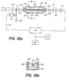
- the apparatus represented on Figs 13a and 18b is intended for measuring optical changes occurring in an optical fiber wave-guide provided by the formation of a product on the surface of said fiber, this measuring being performed by means of ellipsometry.
- Ellustne- tric measurement applications to bioassays have been detailed in our related European application EP 81 810 255.0 and the present reader is referred to this disclosure for general considerations in this field.
- the main difference of the present application with the prior disclosure is the use of an optical fiber instead of the generally known flat reflecting surfaces. Ellipsometry is based on the measurement of changes in the degree of elliptical polarization of light caused by the presence of a film of matter deposited on the reflecting surfaces.
- the optical probe (of which the key can- pcnent is the optical fiber) is made short and rigidly immobilized to minimize the undesirable effect of vibration or other possible perturbations.
- the radial light intensity should have a Gaussian distribution, e.g. that obtained from a laser radiating in the fundamental mode and the beam should be directed axially and centrally on the fiber end.
- This coupling can be achieved by means of a microscope objective.
- the HE 11 mode lower single mode
- multi-mode fibers are usable with single mode signals. This can be made possible (i.e. the proper Gaussian distribution can be selected) by letting the incident beam diameter at the fiber input face be 0.65 times the diameter of the fiber core.
- the fiber length is preferably 10 an or less for the aforementioned reasons.
- It is preferably a high quality single-mode fiber with respect to depolarizaticn and birefringence characteristics. Fibers obtained by CVD techniques such as that disclosed in H. AULICH et al., Applied Optics 19, 22, 3735 (1980) are preferred.
- the apparatus represented on Figs 18a and 18b comprises an optical probe comprising a partially etched piece of optical fiber 101 with a core 101a and a symmetrically removed cladding 101b.
- the technique for removing the cladding is the same as that disclosed for other optical fiber applications in this specification.
- At a very short distance from the bare fiber core (a fraction of a mm) on both sides thereof are placed two glass plates 102 rigidly maintained on "U" shaped brackets 103.
- the clad end portions of the fiber wave-guide are clamped by means of clamps not shown mounted on an adjustable rack not shown, the latter enabling the position of the fiber to be accurately controlled sidewise and up and down.
- the space 104 between the fiber- core and the plates 102 is the reaction site, the liquids to be tested being retained by capillary forces between the fiber and the plates.
- the present apparatus further comprises two microscope objectives 105 and 106 for coupling the input incident beam with the fiber and the output elliptically polarized signal with the detecting system, respectively.
- the incident beam is generated by a light source 107, (in this embodiment a He-Ne laser) the output light of which goes across a polarizer plate 108 and a rotating chopper disk 109 driven by a motor 110 and having a hole 111 for chopping the signal.
- the detecting system of the apparatus comprises a quarter-wave plate 112, a polarization analyzer 113 and a photodetector 114, these elements being similar to corresponding elements described in related application EP 81 810 255.0 and operating similarly.
- the apparatus comprises a lock-in amplifier 115 and associated components, i.e. micro-computer 116 and recorder 117, the functions of these electronic components being essentially the seme as that of the corresponding elements already described earlier in this specification.
- the reference chopped signal used for reference purpose is represented on the drawing as originating from the chopper motor 110 and being transmitted to the amplifier 115 by a line 118.
- the operation of the apparatus is very similar in essence to that described in the previous embodiments combined with the opera- ticn of the apparatus described in related application No. EP 81-810 255.0.
- a reactant e.g. the antibody
- the bare portion of the fiber is first coated with a reactant (e.g. the antibody) as shown by numeral 120 on the drawing by filling the space with the proper so- luticn as shown on the drawing by dashed patterns.
- a reactant e.g. the antibody
- the polarizing elements 112 and 113 see description in application No.
- the solution to be tested is introduced for starting the reaction between the antigen analyte and the antibody coating which results in the growing of the reactant-analyte layer on the wave-guide core and consequent modification of the elliptically polarized output.
- the corresponding change from the photodetector 114 is amplified and monitored in the electronic associated components l16 and 117 and provides the desired data exactly as in the previous embodiments.
- the etched fiber is first cleaned in an aqueous detergent (e.g. a 2% aqueous detergent solution). Then, it is rinsed under running water and imnersed overnight in conc. H2S04. Then, it is rinsed with distilled H 2 0 and dried in warm air. It then readily binds proteins from solutions, e.g. human IgG in buffers.
- an aqueous detergent e.g. a 2% aqueous detergent solution.
- the active portion of the guide after cleaning with H 2 SO 4 and rinsing as above is immersed for an hour in a 15% (w/v) of TiCl 4 in an anhydrous organic solvent like acetone or ethanol. Then, it is washed with distilled water and 0.1 M phosphate buffer (pH -7) and, thereafter, contacted with a human IgG solution (2 g/l in 0.9% NaCl solution or 0.1 M phosphate buffer, pH 7).
- the fiber (or rather the probe) thus made ready for testing against AG's is stored wet in a suitable buffer (or even dry for shorter periods).
- the cell was emptied by absorbing the liquid with an absorbent material and the cell was rinsed with distilled water, the rinsing waters being removed as before. Then a 0.1 M phosphate buffer (pH 7) containing 2 g/1 of bovine serum albumin and 0.5 ml/l of liquid detergent (TMEEN 20) was placed in the cell and left there for 1 hr.
- the serum albumin would fill the "holes" left empty on the glass after coating with the antigen (i.e. since the antigen does normally not attach to all available areas on the glass and, since the antibody to be tested has also affinity for the bare glass, the presence of uncoated areas, the "holes" on the wave-guide, might subsequently introduce errors in the measurements). Since the antibody has no affinity for the bovine serum albumin, this treatment would there simply disable the unused bare portions of the glass. The detergent actually supplements such action.
- the cell was allowed to dry in a current of pure warm air. It was then ready for the experiments. All analysis were dale at room temperature. The various optical and electronic components, except the photomultiplier tube, were turned on and allowed to equilibrate and a sample of antibody solution (2 ml) was introduced into the cell by the same means.
- the antibody selected was rabbit anti-human immunoglobulin from DAKO IMMUNOCHEMICALS, Copenhagen, Denmark in 0.9% NaCl.
- the initial solution as received was a 10 g/l protein solution with a titre of 900/ml, i.e.
- Example 2 the signal obtained from the light emerging from the back-end of the wave-guide and falling on detector 58 was used for generating the rate curve.
- the optical probe was essentially the same as that used in Example 2 (with a coating of AB, rabbit anti-human immunoglobulin).
- Samples of antigen solutions (like in Example 2) were used the concentrations of which are shown in Table III below. The remainder of the operations were carried out exactly as explained in Examples 1 and 2 with the difference that the pho- tomul tiplier 53 was not used and that the signal actually decreased as the reaction went on (this is because the proportion of light not reaching the output of the wave-guide increases as the reaction proceeds).
- the slope of the rate curves recorded as a function of the amount of AG present in the samples is given in Table III.
- Example 5 illustrates a competitive assay method of the type discussed with reference to Fig. 5.
- a fluorescence measurement type of apparatus of the kind disclosed with reference to Fig. 16 was used.
- the optical probe was prepared by coating the corresponding wave-guide 71 with a film of human inmunoglo- bulin (AG) by the same procedure described in Example 1.
- the antibody AB* used was labelled with fluorescein isothiocyanate (FITC) and specific to the antigen tested (it was obtained from DAKO IM-MDNOGLOBULINS, Copenhagen).
- the unlabelled corresponding antibody AB was also obtained from the same source.
- the output face 71b of the wave-guide was coated with black paint to minimize scattered incident light.
- a probe cell was prepared by taking a piece of plastic clad silica fiber from "Quartz & Silice SA", type PCS Fibrosil WSF-UV series (diameter 380 ⁇ m, core 200 ⁇ m, losses 0.14 db/m at 350 nm, 97% transmission) and inserting it by its ends into the grooves of a PVC cell as pictured on Figs 10a and 10b.
- a solution of silicone rubber cement in acetone was used for caulking.
- the cladding was etched away by filling the cell with concentrated H 2 SO 4 and leaving it there for an hour, (unclad section about 10 cm long), then the fiber was made active by the first preferred method described at the last paragraphs before the Examples.
- the method was essentially as described in the foregoing example but replacing the rabbit IgG by a corresponding labelled anti-serum.
- the labelling compound was fluorescein-isothiocyanate "isomer-1" (FITC) and the labelled antiserum was obtained from "Dako". This material strongly absorbs at 492 nm (this wavelength is actually also that which excites fluorescein).
- the tests were performed as already described with various concentrations of FITC-labelled of IgG and also using, in another set of measurements, active fiber sections of only 5 cm. The results are reported in Table VI.
- Example 8 The experiment was actually per famed exactly as in Example 8 but measuring an increase of signal (emitted fluorescence) instead of a decrease as in absorption phenomena.
- the analyte contained 1 ⁇ g/ml of fluorescent IgG + various concentrations of unlabelled human IgG as shown in the left column in the Table.
Landscapes
- Health & Medical Sciences (AREA)
- Chemical & Material Sciences (AREA)
- Immunology (AREA)
- Life Sciences & Earth Sciences (AREA)
- Physics & Mathematics (AREA)
- Pathology (AREA)
- Engineering & Computer Science (AREA)
- Analytical Chemistry (AREA)
- General Physics & Mathematics (AREA)
- General Health & Medical Sciences (AREA)
- Biochemistry (AREA)
- Biomedical Technology (AREA)
- Hematology (AREA)
- Molecular Biology (AREA)
- Urology & Nephrology (AREA)
- Nuclear Medicine, Radiotherapy & Molecular Imaging (AREA)
- Biotechnology (AREA)
- Medicinal Chemistry (AREA)
- Food Science & Technology (AREA)
- Microbiology (AREA)
- Cell Biology (AREA)
- Inorganic Chemistry (AREA)
- Chemical Kinetics & Catalysis (AREA)
- Plasma & Fusion (AREA)
- Investigating Or Analysing Materials By Optical Means (AREA)
- Investigating, Analyzing Materials By Fluorescence Or Luminescence (AREA)
- Investigating Or Analysing Materials By The Use Of Chemical Reactions (AREA)
- Investigating Or Analysing Biological Materials (AREA)
Priority Applications (1)
| Application Number | Priority Date | Filing Date | Title |
|---|---|---|---|
| AT82201107T ATE29073T1 (de) | 1981-09-18 | 1982-09-08 | Verfahren und vorrichtung zur bestimmung von geloesten stoffen mit hilfe eines optischen wellenleiters. |
Applications Claiming Priority (2)
| Application Number | Priority Date | Filing Date | Title |
|---|---|---|---|
| EP81810385 | 1981-09-18 | ||
| EP81810385 | 1981-09-18 |
Publications (2)
| Publication Number | Publication Date |
|---|---|
| EP0075353A1 true EP0075353A1 (fr) | 1983-03-30 |
| EP0075353B1 EP0075353B1 (fr) | 1987-08-19 |
Family
ID=8188676
Family Applications (1)
| Application Number | Title | Priority Date | Filing Date |
|---|---|---|---|
| EP82201107A Expired EP0075353B1 (fr) | 1981-09-18 | 1982-09-08 | Procédé et dispositif pour la détermination de substances en solution à l'aide d'un guide d'ondes optique |
Country Status (10)
| Country | Link |
|---|---|
| US (1) | US4608344A (fr) |
| EP (1) | EP0075353B1 (fr) |
| JP (1) | JPS58501481A (fr) |
| AU (1) | AU557816B2 (fr) |
| CA (1) | CA1189348A (fr) |
| DE (1) | DE3277030D1 (fr) |
| DK (1) | DK166639C (fr) |
| ES (2) | ES8401625A1 (fr) |
| FI (1) | FI76432C (fr) |
| WO (1) | WO1983001112A1 (fr) |
Cited By (7)
| Publication number | Priority date | Publication date | Assignee | Title |
|---|---|---|---|---|
| DE4307042A1 (de) * | 1993-03-05 | 1994-09-08 | S & L Ges Fuer Wissenschaftlic | Verfahren zum optischen qualitativen und quantitativen Nachweis von Molekülen, Biomolekülen und Mikroorganismen |
| WO1996009532A1 (fr) * | 1994-09-22 | 1996-03-28 | Abbott Laboratories | Procede utilisant un guide d'ondes optique pour detecter des evenements de liaison specifique par diffusion de la lumiere |
| WO1997032212A1 (fr) * | 1996-03-01 | 1997-09-04 | Beckman Instruments, Inc. | Systeme d'essais multiples simultanes de fixation de ligands |
| US5952035A (en) * | 1996-03-15 | 1999-09-14 | Ia, Inc. | Surface treatment and light injection method and apparatus |
| US8111401B2 (en) | 1999-11-05 | 2012-02-07 | Robert Magnusson | Guided-mode resonance sensors employing angular, spectral, modal, and polarization diversity for high-precision sensing in compact formats |
| US9778267B2 (en) | 2007-07-11 | 2017-10-03 | X-Body, Inc. | Methods for identifying modulators of ion channels |
| US10359573B2 (en) | 1999-11-05 | 2019-07-23 | Board Of Regents, The University Of Texas System | Resonant waveguide-granting devices and methods for using same |
Families Citing this family (151)
| Publication number | Priority date | Publication date | Assignee | Title |
|---|---|---|---|---|
| US4582809A (en) * | 1982-06-14 | 1986-04-15 | Myron J. Block | Apparatus including optical fiber for fluorescence immunoassay |
| US4447546A (en) * | 1982-08-23 | 1984-05-08 | Myron J. Block | Fluorescent immunoassay employing optical fiber in capillary tube |
| DE3376685D1 (en) * | 1982-12-21 | 1988-06-23 | Ares Serono Nv | Assay technique |
| GB8314523D0 (en) * | 1983-05-25 | 1983-06-29 | Lowe C R | Diagnostic device |
| US4558014A (en) * | 1983-06-13 | 1985-12-10 | Myron J. Block | Assay apparatus and methods |
| DE3344019C2 (de) * | 1983-12-06 | 1995-05-04 | Max Planck Gesellschaft | Vorrichtung zur optischen Messung der Konzentration einer in einer Probe enthaltenen Komponente |
| DE3588124T2 (de) * | 1984-06-13 | 1997-02-20 | Applied Research Systems | Vorrichtung, mit Verwendung in chemischen Prüfverfahren |
| US4647544A (en) * | 1984-06-25 | 1987-03-03 | Nicoli David F | Immunoassay using optical interference detection |
| USRE33581E (en) * | 1984-06-25 | 1991-04-30 | Immunoassay using optical interference detection | |
| GB8423204D0 (en) * | 1984-09-14 | 1984-10-17 | Comtech Res Unit | Assay technique and equipment |
| US4668636A (en) * | 1984-11-06 | 1987-05-26 | Battelle Memorial Institute | Analytical assembly usable in apparatuses for optically determining species in solution |
| DE3480490D1 (en) * | 1984-12-10 | 1989-12-21 | Prutec Ltd | Optical test probe and apparatus for optically determining species in solution |
| EP0184600B1 (fr) * | 1984-12-10 | 1990-03-14 | Prutec Limited | Méthode pour la détermination optique de paramètres d'espèces chimiques dans un échantillon liquide |
| JPH0660876B2 (ja) * | 1985-03-30 | 1994-08-10 | 株式会社東芝 | 分析装置 |
| GB8509491D0 (en) * | 1985-04-12 | 1985-05-15 | Plessey Co Plc | Optic waveguide biosensors |
| CH665033A5 (fr) * | 1985-07-01 | 1988-04-15 | Prutec Ltd | Guide d'onde utilisable comme sonde optique dans l'analyse spectroscopique a reflexion interne. |
| DE3689095T2 (de) * | 1985-07-31 | 1994-01-27 | Ciba Corning Diagnostics Corp | Dielektrischer Wellenleiter zur Verwendung in einem Analyseverfahren. |
| US4716121A (en) * | 1985-09-09 | 1987-12-29 | Ord, Inc. | Fluorescent assays, including immunoassays, with feature of flowing sample |
| JPS6275230A (ja) * | 1985-09-26 | 1987-04-07 | チバ−ガイギ− アクチエンゲゼルシヤフト | 分析法 |
| DE3543108A1 (de) * | 1985-12-06 | 1987-06-19 | Strahlen Umweltforsch Gmbh | Verfahren zur messung der wechselwirkung im wand/fluid-bereich |
| JPH01502131A (ja) * | 1986-01-14 | 1989-07-27 | レビン ハーマン ダブリュ | エバネッセント波背景螢光/吸光度の検出 |
| US4945245A (en) * | 1986-01-14 | 1990-07-31 | Levin Herman W | Evanescent wave background fluorescence/absorbance detection |
| US4852967A (en) * | 1986-03-25 | 1989-08-01 | Ciba Corning Diagnostics Corp. | Evanescent wave sensors |
| EP0245206A1 (fr) * | 1986-05-05 | 1987-11-11 | IntraCel Corporation | Méthode analytique de détection et de mesure d'un acide nucléique spécifiquement séquencé |
| JP2591750B2 (ja) * | 1986-06-26 | 1997-03-19 | オ−ソ・ダイアグノステイツク・システムズ・インコ−ポレ−テツド | 免疫分析システム |
| BE1000572A4 (fr) * | 1987-05-20 | 1989-02-07 | Block Myron J | Cellule rta, appareil et procede pour titrer un polynucleotide dans un liquide. |
| US4834496A (en) * | 1987-05-22 | 1989-05-30 | American Telephone And Telegraph Company, At&T Bell Laboratories | Optical fiber sensors for chemical detection |
| AT389590B (de) * | 1987-05-27 | 1989-12-27 | Avl Verbrennungskraft Messtech | Verfahren zur kontinuierlichen, quantitativen bestimmung von schwefeldioxid und anordnung zur durchfuehrung des verfahrens |
| US4909990A (en) * | 1987-09-02 | 1990-03-20 | Myron J. Block | Immunoassay apparatus |
| WO1989007254A1 (fr) * | 1988-01-28 | 1989-08-10 | Spectran Corporation | Sonde a emission infrarouge et analyses au moyen de celle-ci |
| US4827121A (en) * | 1988-02-24 | 1989-05-02 | Measurex Corporation | System for detecting chemical changes in materials by embedding in materials an unclad fiber optic sensor section |
| US4913519A (en) * | 1988-03-04 | 1990-04-03 | Fiberchem Inc. | Optical sensor for the detection of ice formation and other chemical species |
| GB8807488D0 (en) * | 1988-03-29 | 1988-05-05 | Ares Serono Res & Dev Ltd | Method of assay |
| US4893894A (en) * | 1988-04-29 | 1990-01-16 | Mine Safety Appliances Company | Evanescent sensor |
| GB8817710D0 (en) * | 1988-07-25 | 1988-09-01 | Ares Serono Res & Dev Ltd | Method of assay |
| GB2223841A (en) * | 1988-08-31 | 1990-04-18 | Red Kite Tech | Parameter measurement using refractive index change |
| US4940328A (en) * | 1988-11-04 | 1990-07-10 | Georgia Tech Research Corporation | Optical sensing apparatus and method |
| SE8902043L (sv) * | 1988-11-10 | 1990-05-11 | Pharmacia Ab | Foerfarande foer karakterisering av makromolekyler |
| US4892383A (en) * | 1989-02-17 | 1990-01-09 | Fiberchem Inc. | Reservoir fiber optic chemical sensors |
| US5266486A (en) * | 1989-05-12 | 1993-11-30 | Nvl Photronics Corporation | Method and apparatus for detecting biological activities in a specimen |
| US5082629A (en) * | 1989-12-29 | 1992-01-21 | The Board Of The University Of Washington | Thin-film spectroscopic sensor |
| US5377008A (en) * | 1990-09-20 | 1994-12-27 | Battelle Memorial Institute | Integrated optical compensating refractometer apparatus |
| EP0510175B1 (fr) * | 1990-11-13 | 1996-06-12 | Myron J. Block | Appareil d'analyse par fluorescence |
| US5212099A (en) * | 1991-01-18 | 1993-05-18 | Eastman Kodak Company | Method and apparatus for optically measuring concentration of an analyte |
| US5192510A (en) * | 1991-01-30 | 1993-03-09 | E. I. Du Pont De Nemours And Company | Apparatus for performing fluorescent assays which separates bulk and evanescent fluorescence |
| CA2069537A1 (fr) * | 1991-06-07 | 1992-12-08 | Thomas A. Cook | Systeme d'analyse a sorties multiples utilisant un capteur d'ondes evanescentes |
| FR2685086A1 (fr) * | 1991-12-17 | 1993-06-18 | Devienne Marcel | Procede d'observation sequentielle des etats successifs d'une reaction chimique. |
| WO1993020240A1 (fr) * | 1992-04-06 | 1993-10-14 | Abbott Laboratories | Procede et dispositif de detection d'acide nucleique ou d'analyte au moyen d'une technique de reflexion interne totale |
| US5777726A (en) * | 1992-05-12 | 1998-07-07 | Raytheon Company | Spectrophotometric supercritical fluid contamination monitor |
| GB9212305D0 (en) * | 1992-06-10 | 1992-07-22 | Applied Research Systems | Sensor for optical assay |
| US5326531A (en) * | 1992-12-11 | 1994-07-05 | Puritan-Bennett Corporation | CO2 sensor using a hydrophilic polyurethane matrix and process for manufacturing |
| US5448071A (en) * | 1993-04-16 | 1995-09-05 | Bruce W. McCaul | Gas spectroscopy |
| US5625189A (en) * | 1993-04-16 | 1997-04-29 | Bruce W. McCaul | Gas spectroscopy |
| US5413939A (en) * | 1993-06-29 | 1995-05-09 | First Medical, Inc. | Solid-phase binding assay system for interferometrically measuring analytes bound to an active receptor |
| US6287850B1 (en) * | 1995-06-07 | 2001-09-11 | Affymetrix, Inc. | Bioarray chip reaction apparatus and its manufacture |
| US5814565A (en) * | 1995-02-23 | 1998-09-29 | University Of Utah Research Foundation | Integrated optic waveguide immunosensor |
| US5922534A (en) | 1995-03-28 | 1999-07-13 | Hewlett-Packard Company | Dry biochemical assay plate and method for making the same |
| US5633724A (en) * | 1995-08-29 | 1997-05-27 | Hewlett-Packard Company | Evanescent scanning of biochemical array |
| BR9611136A (pt) * | 1995-10-23 | 1999-09-14 | Cytometrics Inc | Processo e aparelho para análise de imagem refletida |
| GB9609653D0 (en) * | 1996-05-09 | 1996-07-10 | Applied Research Ars Holding N | Method of assay |
| US6331275B1 (en) | 1996-07-08 | 2001-12-18 | Burstein Technologies, Inc. | Spatially addressable, cleavable reflective signal elements, assay device and method |
| US6342349B1 (en) | 1996-07-08 | 2002-01-29 | Burstein Technologies, Inc. | Optical disk-based assay devices and methods |
| CN1230216A (zh) | 1996-07-08 | 1999-09-29 | 伯斯坦恩实验室股份有限公司 | 可断裂信号元件装置和方法 |
| US20050214827A1 (en) * | 1996-07-08 | 2005-09-29 | Burstein Technologies, Inc. | Assay device and method |
| US7335164B2 (en) | 1996-07-15 | 2008-02-26 | Ntc Technology, Inc. | Multiple function airway adapter |
| US6325978B1 (en) | 1998-08-04 | 2001-12-04 | Ntc Technology Inc. | Oxygen monitoring and apparatus |
| US20070225612A1 (en) * | 1996-07-15 | 2007-09-27 | Mace Leslie E | Metabolic measurements system including a multiple function airway adapter |
| US6815211B1 (en) | 1998-08-04 | 2004-11-09 | Ntc Technology | Oxygen monitoring methods and apparatus (I) |
| US5982534A (en) * | 1997-06-18 | 1999-11-09 | The Regents Of The University Of California | Specimen illumination apparatus with optical cavity for dark field illumination |
| US6222619B1 (en) * | 1997-09-18 | 2001-04-24 | University Of Utah Research Foundation | Diagnostic device and method |
| DE19747572C1 (de) * | 1997-10-28 | 1999-04-08 | Inst Chemo Biosensorik | Vorrichtung und Verfahren zur Durchführung von Fluoreszenzimmuntests |
| US6224830B1 (en) * | 1998-01-30 | 2001-05-01 | The Governors Of The University Of Alberta | Absorbance cell for microfluid devices |
| US6326213B1 (en) * | 1998-02-09 | 2001-12-04 | The Boards Of Govenors For Higher Education, State Of Rhode Island And Providence Plantations | Acoustic standing-wave enhancement of a fiber-optic Salmonella biosensor |
| US6300082B1 (en) * | 1998-03-20 | 2001-10-09 | Ia, Inc. | Method and apparatus for measurement of the effect of test compounds on signal transduction at the level of biological receptors |
| US6251688B1 (en) * | 1998-03-20 | 2001-06-26 | Ia, Inc. | Method and apparatus for measurement of binding between a protein and a nucleotide |
| EP1082601B1 (fr) * | 1998-05-25 | 2005-08-10 | Jennissen, Herbert P. | Analyseur de cisaillement de flux passant pour molecules biologiquement actives se trouvant dans des couches de liquide sur des surfaces, procede d'analyse d'un liquide et procede de determination de l'epaisseur d'une couche de liquide ultra mince |
| US6429023B1 (en) | 1998-07-20 | 2002-08-06 | Shayda Technologies, Inc. | Biosensors with polymeric optical waveguides |
| WO2000005582A2 (fr) * | 1998-07-21 | 2000-02-03 | Burstein Laboratories, Inc. | Dispositifs de dosage utilisant des disques optiques et methodes correspondantes |
| US6266998B1 (en) * | 1999-04-01 | 2001-07-31 | DRäGERWERK AKTIENGESELLSCHAFT | System for measuring the concentration of gases |
| EE04249B1 (et) * | 1999-04-21 | 2004-02-16 | Asper O� | Meetod biopolümeermaatriksi lugemiseks ja fluorestsentsdetektor |
| US6399295B1 (en) | 1999-12-17 | 2002-06-04 | Kimberly-Clark Worldwide, Inc. | Use of wicking agent to eliminate wash steps for optical diffraction-based biosensors |
| ATE486275T1 (de) * | 2000-03-22 | 2010-11-15 | Axela Inc | Verfahren und vorrichtung zur bestimmung mehrerer analyten |
| US6927851B2 (en) * | 2000-03-31 | 2005-08-09 | Neogen Corporation | Methods and apparatus to improve the sensitivity and reproducibility of bioluminescent analytical methods |
| US7205347B2 (en) * | 2000-10-19 | 2007-04-17 | Trans Photonics, Llc. | Substituted-polyaryl chromophoric compounds |
| US7300803B2 (en) | 2000-10-30 | 2007-11-27 | Sru Biosystems, Inc. | Label-free methods for performing assays using a colorimetric resonant reflectance optical biosensor |
| US7371562B2 (en) | 2000-10-30 | 2008-05-13 | Sru Biosystems, Inc. | Guided mode resonant filter biosensor using a linear grating surface structure |
| US7615339B2 (en) | 2000-10-30 | 2009-11-10 | Sru Biosystems, Inc. | Method for producing a colorimetric resonant reflection biosensor on rigid surfaces |
| US7175980B2 (en) | 2000-10-30 | 2007-02-13 | Sru Biosystems, Inc. | Method of making a plastic colorimetric resonant biosensor device with liquid handling capabilities |
| US7142296B2 (en) | 2000-10-30 | 2006-11-28 | Sru Biosystems, Inc. | Method and apparatus for detecting biomolecular interactions |
| US7202076B2 (en) * | 2000-10-30 | 2007-04-10 | Sru Biosystems, Inc. | Label-free high-throughput optical technique for detecting biomolecular interactions |
| US20030113766A1 (en) * | 2000-10-30 | 2003-06-19 | Sru Biosystems, Llc | Amine activated colorimetric resonant biosensor |
| US20030092075A1 (en) * | 2000-10-30 | 2003-05-15 | Sru Biosystems, Llc | Aldehyde chemical surface activation processes and test methods for colorimetric resonant sensors |
| US7306827B2 (en) * | 2000-10-30 | 2007-12-11 | Sru Biosystems, Inc. | Method and machine for replicating holographic gratings on a substrate |
| US7264973B2 (en) * | 2000-10-30 | 2007-09-04 | Sru Biosystems, Inc. | Label-free methods for performing assays using a colorimetric resonant optical biosensor |
| US7575939B2 (en) | 2000-10-30 | 2009-08-18 | Sru Biosystems, Inc. | Optical detection of label-free biomolecular interactions using microreplicated plastic sensor elements |
| US7875434B2 (en) | 2000-10-30 | 2011-01-25 | Sru Biosystems, Inc. | Label-free methods for performing assays using a colorimetric resonant reflectance optical biosensor |
| US7023544B2 (en) * | 2000-10-30 | 2006-04-04 | Sru Biosystems, Inc. | Method and instrument for detecting biomolecular interactions |
| US7101660B2 (en) * | 2000-10-30 | 2006-09-05 | Sru Biosystems, Inc. | Method for producing a colorimetric resonant reflection biosensor on rigid surfaces |
| US7094595B2 (en) | 2000-10-30 | 2006-08-22 | Sru Biosystems, Inc. | Label-free high-throughput optical technique for detecting biomolecular interactions |
| US6951715B2 (en) * | 2000-10-30 | 2005-10-04 | Sru Biosystems, Inc. | Optical detection of label-free biomolecular interactions using microreplicated plastic sensor elements |
| US7153702B2 (en) | 2000-10-30 | 2006-12-26 | Sru Biosystems, Inc. | Label-free methods for performing assays using a colorimetric resonant reflectance optical biosensor |
| US7070987B2 (en) * | 2000-10-30 | 2006-07-04 | Sru Biosystems, Inc. | Guided mode resonant filter biosensor using a linear grating surface structure |
| US7217574B2 (en) * | 2000-10-30 | 2007-05-15 | Sru Biosystems, Inc. | Method and apparatus for biosensor spectral shift detection |
| US6937323B2 (en) * | 2000-11-08 | 2005-08-30 | Burstein Technologies, Inc. | Interactive system for analyzing biological samples and processing related information and the use thereof |
| US7087203B2 (en) * | 2000-11-17 | 2006-08-08 | Nagaoka & Co., Ltd. | Methods and apparatus for blood typing with optical bio-disc |
| US7026131B2 (en) * | 2000-11-17 | 2006-04-11 | Nagaoka & Co., Ltd. | Methods and apparatus for blood typing with optical bio-discs |
| US6760298B2 (en) * | 2000-12-08 | 2004-07-06 | Nagaoka & Co., Ltd. | Multiple data layer optical discs for detecting analytes |
| AU2002239552A1 (en) * | 2000-12-08 | 2002-06-18 | Burstein Technologies, Inc. | Multiple data layer optical discs for detecting analytes |
| WO2002059583A1 (fr) * | 2001-01-23 | 2002-08-01 | Dublin City University | Capteur dont le fonctionnement est fonde sur la luminescence |
| EP1493014A2 (fr) | 2001-04-11 | 2005-01-05 | Burstein Technologies, Inc. | Dosages a parametres multiples mettant en oeuvre des disques d'analyse, et procedes s'y rapportant |
| US20020171838A1 (en) * | 2001-05-16 | 2002-11-21 | Pal Andrew Attila | Variable sampling control for rendering pixelization of analysis results in a bio-disc assembly and apparatus relating thereto |
| US7098041B2 (en) * | 2001-12-11 | 2006-08-29 | Kimberly-Clark Worldwide, Inc. | Methods to view and analyze the results from diffraction-based diagnostics |
| US7102752B2 (en) * | 2001-12-11 | 2006-09-05 | Kimberly-Clark Worldwide, Inc. | Systems to view and analyze the results from diffraction-based diagnostics |
| US7018842B2 (en) * | 2002-02-28 | 2006-03-28 | Agilent Technologies, Inc. | Reading dry chemical arrays through the substrate |
| SG104963A1 (en) * | 2002-04-03 | 2004-07-30 | Ntu Ventures Private Ltd | Fiber optic bio-sensor |
| US6620623B1 (en) * | 2002-05-06 | 2003-09-16 | The University Of Chicago | Biochip reader with enhanced illumination and bioarray positioning apparatus |
| US20030224370A1 (en) * | 2002-05-31 | 2003-12-04 | William Rassman | Method and apparatus for recognizing molecular compounds |
| US7429492B2 (en) * | 2002-09-09 | 2008-09-30 | Sru Biosystems, Inc. | Multiwell plates with integrated biosensors and membranes |
| US7927822B2 (en) * | 2002-09-09 | 2011-04-19 | Sru Biosystems, Inc. | Methods for screening cells and antibodies |
| JP2007528692A (ja) * | 2003-05-28 | 2007-10-18 | メイバン・テクノロジーズ・エルエルシー | 分子化合物を認識する方法及び装置 |
| JP4130391B2 (ja) * | 2003-08-28 | 2008-08-06 | 富士通株式会社 | 被検体評価装置、被検体評価方法および被検体評価装置の製造方法 |
| CN100559182C (zh) * | 2003-08-29 | 2009-11-11 | 株式会社东芝 | 显色试剂、浓度测定试剂盒、浓度测定方法和在该方法中使用的传感器芯片 |
| AU2003267176A1 (en) * | 2003-09-12 | 2005-04-27 | Maven Technologies, Llc | Method and apparatus for recognizing molecular compounds |
| US8298780B2 (en) * | 2003-09-22 | 2012-10-30 | X-Body, Inc. | Methods of detection of changes in cells |
| WO2005047904A2 (fr) * | 2003-11-06 | 2005-05-26 | Sru Biosystems, Inc. | Surface a fonction amine a densite elevee |
| SE529711C2 (sv) * | 2006-03-22 | 2007-11-06 | Aamic Ab | Fluorescensläsare |
| US20070235397A1 (en) * | 2006-03-30 | 2007-10-11 | Wannop George M | Storage bin and frame system |
| ES2388110T3 (es) | 2006-12-12 | 2012-10-09 | Koninklijke Philips Electronics N.V. | Dispositivo de sensor microelectrónico para detectar partículas de marcador |
| JP5238171B2 (ja) * | 2007-03-14 | 2013-07-17 | 株式会社東芝 | 光導波路型抗体チップ |
| JP2010525334A (ja) * | 2007-04-19 | 2010-07-22 | エス アール ユー バイオシステムズ,インコーポレイテッド | 固定化された標的と直接結合する小分子を検出するためにバイオセンサーを使用する方法 |
| US9134307B2 (en) | 2007-07-11 | 2015-09-15 | X-Body, Inc. | Method for determining ion channel modulating properties of a test reagent |
| EP2174114A2 (fr) * | 2007-07-26 | 2010-04-14 | Koninklijke Philips Electronics N.V. | Dispositif détecteur microélectronique pour des examens optiques avec réflexion interne totale |
| JP4970217B2 (ja) * | 2007-11-07 | 2012-07-04 | 株式会社東芝 | 物質の測定方法 |
| US8257936B2 (en) | 2008-04-09 | 2012-09-04 | X-Body Inc. | High resolution label free analysis of cellular properties |
| US20100015721A1 (en) * | 2008-06-04 | 2010-01-21 | Sru Biosystems, Inc. | Detection of Promiscuous Small Submicrometer Aggregates |
| US8300993B2 (en) * | 2009-03-02 | 2012-10-30 | Mbio Diagnostics, Inc. | Waveguide with integrated lens |
| US9658222B2 (en) | 2009-03-02 | 2017-05-23 | Mbio Diagnostics, Inc. | Planar waveguide based cartridges and associated methods for detecting target analyte |
| US8331751B2 (en) * | 2009-03-02 | 2012-12-11 | mBio Diagnositcs, Inc. | Planar optical waveguide with core of low-index-of-refraction interrogation medium |
| US9212995B2 (en) | 2009-03-02 | 2015-12-15 | Mbio Diagnostics, Inc. | System and method for detecting multiple molecules in one assay |
| US20100291575A1 (en) * | 2009-05-15 | 2010-11-18 | Sru Biosystems, Inc. | Detection of Changes in Cell Populations and Mixed Cell Populations |
| JP4948624B2 (ja) * | 2010-05-06 | 2012-06-06 | シャープ株式会社 | 濁度検知器 |
| TW201217783A (en) | 2010-09-15 | 2012-05-01 | Mbio Diagnostics Inc | System and method for detecting multiple molecules in one assay |
| US8218133B2 (en) * | 2010-09-16 | 2012-07-10 | Sondex Limited | Refractive index tool and method |
| KR101188344B1 (ko) * | 2011-01-14 | 2012-10-05 | 광주과학기술원 | 클래딩층 내 금속 나노 입자가 도핑된 광섬유, 코어리스 광섬유 및 이들의 제조 방법 |
| EP2699906B1 (fr) | 2011-04-20 | 2017-11-29 | Access Medical Systems, Ltd. | Amplification cyclique de polymère luminescent |
| EP2522276A1 (fr) | 2011-05-13 | 2012-11-14 | General Electric Company | Airway adapter and gas analyzer for measuring oxygen concentration of a respiratory gas |
| BR112014010235A2 (pt) * | 2011-11-03 | 2017-04-18 | Koninklijke Philips Nv | cartucho para o teste óptico de uma amostra, aparelho sensor para o teste óptico de uma amostra, e método de teste óptico de uma amostra |
| CA2908176A1 (fr) * | 2013-06-03 | 2014-12-11 | Ventana Medical Systems, Inc. | Systeme d'imagerie par fluorescence pour detection de tissu |
| CN105445253B (zh) * | 2015-11-12 | 2018-05-18 | 北京农业智能装备技术研究中心 | 一种用于检测水中抗生素浓度的设备 |
| TWI565941B (zh) * | 2016-01-07 | 2017-01-11 | 國立交通大學 | 光學量測系統及其濃度感測裝置 |
| WO2019084766A1 (fr) * | 2017-10-31 | 2019-05-09 | 深圳大学 | Coupleur de fibre optique hybride et son procédé de préparation |
Citations (3)
| Publication number | Priority date | Publication date | Assignee | Title |
|---|---|---|---|---|
| US3939350A (en) * | 1974-04-29 | 1976-02-17 | Board Of Trustees Of The Leland Stanford Junior University | Fluorescent immunoassay employing total reflection for activation |
| US4050895A (en) * | 1975-09-26 | 1977-09-27 | Monsanto Research Corporation | Optical analytical device, waveguide and method |
| WO1981000912A1 (fr) * | 1979-09-20 | 1981-04-02 | R Buckles | Procede et appareil d'analyses |
-
1982
- 1982-09-08 AU AU89041/82A patent/AU557816B2/en not_active Expired
- 1982-09-08 JP JP57502805A patent/JPS58501481A/ja active Granted
- 1982-09-08 DE DE8282201107T patent/DE3277030D1/de not_active Expired
- 1982-09-08 WO PCT/EP1982/000195 patent/WO1983001112A1/fr not_active Ceased
- 1982-09-08 EP EP82201107A patent/EP0075353B1/fr not_active Expired
- 1982-09-08 US US06/499,164 patent/US4608344A/en not_active Ceased
- 1982-09-15 CA CA000411516A patent/CA1189348A/fr not_active Expired
- 1982-09-17 ES ES515787A patent/ES8401625A1/es not_active Expired
-
1983
- 1983-05-17 DK DK219683A patent/DK166639C/da not_active IP Right Cessation
- 1983-05-18 FI FI831745A patent/FI76432C/fi not_active IP Right Cessation
- 1983-07-15 ES ES524166A patent/ES8405523A1/es not_active Expired
Patent Citations (3)
| Publication number | Priority date | Publication date | Assignee | Title |
|---|---|---|---|---|
| US3939350A (en) * | 1974-04-29 | 1976-02-17 | Board Of Trustees Of The Leland Stanford Junior University | Fluorescent immunoassay employing total reflection for activation |
| US4050895A (en) * | 1975-09-26 | 1977-09-27 | Monsanto Research Corporation | Optical analytical device, waveguide and method |
| WO1981000912A1 (fr) * | 1979-09-20 | 1981-04-02 | R Buckles | Procede et appareil d'analyses |
Non-Patent Citations (2)
| Title |
|---|
| ANALYTICAL CHEMISTRY, vol. 45, no. 4, April 1973, pages 687-691; * |
| LASER FOCUS, vol. 15, no. 8, August 1979, pages 60-65; * |
Cited By (9)
| Publication number | Priority date | Publication date | Assignee | Title |
|---|---|---|---|---|
| DE4307042A1 (de) * | 1993-03-05 | 1994-09-08 | S & L Ges Fuer Wissenschaftlic | Verfahren zum optischen qualitativen und quantitativen Nachweis von Molekülen, Biomolekülen und Mikroorganismen |
| WO1996009532A1 (fr) * | 1994-09-22 | 1996-03-28 | Abbott Laboratories | Procede utilisant un guide d'ondes optique pour detecter des evenements de liaison specifique par diffusion de la lumiere |
| EP1441217A2 (fr) | 1994-09-22 | 2004-07-28 | Abbott Laboratories | Procédé utilisant un guide d'ondes optique pour détecter des événements de liaison spécifique par diffusion de la lumière |
| EP1441217A3 (fr) * | 1994-09-22 | 2007-07-04 | Abbott Laboratories | Procédé utilisant un guide d'ondes optique pour détecter des événements de liaison spécifique par diffusion de la lumière |
| WO1997032212A1 (fr) * | 1996-03-01 | 1997-09-04 | Beckman Instruments, Inc. | Systeme d'essais multiples simultanes de fixation de ligands |
| US5952035A (en) * | 1996-03-15 | 1999-09-14 | Ia, Inc. | Surface treatment and light injection method and apparatus |
| US8111401B2 (en) | 1999-11-05 | 2012-02-07 | Robert Magnusson | Guided-mode resonance sensors employing angular, spectral, modal, and polarization diversity for high-precision sensing in compact formats |
| US10359573B2 (en) | 1999-11-05 | 2019-07-23 | Board Of Regents, The University Of Texas System | Resonant waveguide-granting devices and methods for using same |
| US9778267B2 (en) | 2007-07-11 | 2017-10-03 | X-Body, Inc. | Methods for identifying modulators of ion channels |
Also Published As
| Publication number | Publication date |
|---|---|
| ES524166A0 (es) | 1984-06-01 |
| JPS58501481A (ja) | 1983-09-01 |
| ES515787A0 (es) | 1983-12-16 |
| DK219683A (da) | 1983-05-17 |
| AU8904182A (en) | 1983-04-08 |
| FI831745A0 (fi) | 1983-05-18 |
| US4608344A (en) | 1986-08-26 |
| DK219683D0 (da) | 1983-05-17 |
| DK166639C (da) | 1993-11-08 |
| FI831745L (fi) | 1983-05-18 |
| AU557816B2 (en) | 1987-01-08 |
| ES8401625A1 (es) | 1983-12-16 |
| FI76432B (fi) | 1988-06-30 |
| JPH037270B2 (fr) | 1991-02-01 |
| EP0075353B1 (fr) | 1987-08-19 |
| CA1189348A (fr) | 1985-06-25 |
| ES8405523A1 (es) | 1984-06-01 |
| FI76432C (fi) | 1988-10-10 |
| DE3277030D1 (en) | 1987-09-24 |
| WO1983001112A1 (fr) | 1983-03-31 |
| DK166639B (da) | 1993-06-21 |
Similar Documents
| Publication | Publication Date | Title |
|---|---|---|
| EP0075353B1 (fr) | Procédé et dispositif pour la détermination de substances en solution à l'aide d'un guide d'ondes optique | |
| USRE33064E (en) | Method for the determination of species in solution with an optical wave-guide | |
| US5156976A (en) | Evanescent wave sensor shell and apparatus | |
| US5478755A (en) | Long range surface plasma resonance immunoassay | |
| Andrade et al. | Remote fiber-optic biosensors based on evanescent-excited fluoro-immunoassay: concept and progress | |
| US5830766A (en) | Enhanced signal-to-noise ratio and sensitivity optical immunoassay | |
| US5350697A (en) | Scattered light detection apparatus | |
| EP0103426B1 (fr) | Appareil et méthode pour immunoessais | |
| US4818710A (en) | Method for optically ascertaining parameters of species in a liquid analyte | |
| US5340715A (en) | Multiple surface evanescent wave sensor with a reference | |
| US4880752A (en) | Dielectric waveguide sensors and their use in immunoassays | |
| US4368047A (en) | Process for conducting fluorescence immunoassays without added labels and employing attenuated internal reflection | |
| JPH0643964B2 (ja) | 流体試料を検定するための装置 | |
| JPH0627741B2 (ja) | 免疫検定装置及び方法 | |
| JPH05504626A (ja) | 化学又は生化学試験に用いる試料セル | |
| EP0382832B1 (fr) | Methode d'analyse d'un ligand dans un echantillon | |
| EP1645865A1 (fr) | Biopuce a reseau de fibres optiques basee sur la spectroscopie a interferences par reflectometrie en lumiere blanche | |
| US4988630A (en) | Multiple beam laser instrument for measuring agglutination reactions | |
| EP0254430B1 (fr) | Un système d'essai immunologique utilisant de la lumière dispersée | |
| EP0175585B1 (fr) | Capteurs diélectriques en guides d'ondes et leur application pour essais immunologiques | |
| JP2000121552A (ja) | Sprセンサセル及びこれを用いた免疫反応測定装置 | |
| Sutherland et al. | Interface immunoassays using the evanescent wave | |
| JP2000171391A (ja) | Sprセンサセル及びこれを用いた免疫反応測定装置 | |
| Ives et al. | Total internal reflection fluorescence surface sensors | |
| NO161945B (no) | Fremgangsmaate og apparat for bestemmelse av stoffer i opploesning med en optisk boelgeleder. |
Legal Events
| Date | Code | Title | Description |
|---|---|---|---|
| PUAI | Public reference made under article 153(3) epc to a published international application that has entered the european phase |
Free format text: ORIGINAL CODE: 0009012 |
|
| AK | Designated contracting states |
Designated state(s): AT BE CH DE FR GB IT LI LU NL SE |
|
| 17P | Request for examination filed |
Effective date: 19830811 |
|
| 17Q | First examination report despatched |
Effective date: 19860801 |
|
| GRAA | (expected) grant |
Free format text: ORIGINAL CODE: 0009210 |
|
| AK | Designated contracting states |
Kind code of ref document: B1 Designated state(s): AT BE CH DE FR GB IT LI LU NL SE |
|
| REF | Corresponds to: |
Ref document number: 29073 Country of ref document: AT Date of ref document: 19870915 Kind code of ref document: T |
|
| REF | Corresponds to: |
Ref document number: 3277030 Country of ref document: DE Date of ref document: 19870924 |
|
| ET | Fr: translation filed | ||
| ITF | It: translation for a ep patent filed | ||
| BECA | Be: change of holder's address |
Free format text: 870819 *PRUTEC LTD:142 HOLBORN BARS, LONDON EC1N 2NH |
|
| BECH | Be: change of holder |
Free format text: 870819 *PRUTEC LTD |
|
| PLBI | Opposition filed |
Free format text: ORIGINAL CODE: 0009260 |
|
| 26 | Opposition filed |
Opponent name: FISONS PLC Effective date: 19880516 |
|
| NLR1 | Nl: opposition has been filed with the epo |
Opponent name: FISONS PLC |
|
| REG | Reference to a national code |
Ref country code: CH Ref legal event code: PUE Owner name: PRUTEC LIMITED |
|
| REG | Reference to a national code |
Ref country code: FR Ref legal event code: TP |
|
| REG | Reference to a national code |
Ref country code: GB Ref legal event code: 732 |
|
| NLS | Nl: assignments of ep-patents |
Owner name: PRUTEC LIMITED TE LONDEN, GROOT-BRITTANNIE. |
|
| ITPR | It: changes in ownership of a european patent |
Owner name: CESSIONE;PRUTEC LIMITED |
|
| PLAB | Opposition data, opponent's data or that of the opponent's representative modified |
Free format text: ORIGINAL CODE: 0009299OPPO |
|
| R26 | Opposition filed (corrected) |
Opponent name: FISONS PLC Effective date: 19880516 |
|
| ITTA | It: last paid annual fee | ||
| EPTA | Lu: last paid annual fee | ||
| PGFP | Annual fee paid to national office [announced via postgrant information from national office to epo] |
Ref country code: AT Payment date: 19940909 Year of fee payment: 13 |
|
| PGFP | Annual fee paid to national office [announced via postgrant information from national office to epo] |
Ref country code: SE Payment date: 19940914 Year of fee payment: 13 |
|
| PGFP | Annual fee paid to national office [announced via postgrant information from national office to epo] |
Ref country code: CH Payment date: 19940928 Year of fee payment: 13 |
|
| PGFP | Annual fee paid to national office [announced via postgrant information from national office to epo] |
Ref country code: NL Payment date: 19940930 Year of fee payment: 13 Ref country code: DE Payment date: 19940930 Year of fee payment: 13 |
|
| EAL | Se: european patent in force in sweden |
Ref document number: 82201107.8 |
|
| PGFP | Annual fee paid to national office [announced via postgrant information from national office to epo] |
Ref country code: GB Payment date: 19950829 Year of fee payment: 14 |
|
| PGFP | Annual fee paid to national office [announced via postgrant information from national office to epo] |
Ref country code: FR Payment date: 19950831 Year of fee payment: 14 |
|
| PGFP | Annual fee paid to national office [announced via postgrant information from national office to epo] |
Ref country code: LU Payment date: 19950901 Year of fee payment: 14 |
|
| PGFP | Annual fee paid to national office [announced via postgrant information from national office to epo] |
Ref country code: BE Payment date: 19950905 Year of fee payment: 14 |
|
| RDAG | Patent revoked |
Free format text: ORIGINAL CODE: 0009271 |
|
| STAA | Information on the status of an ep patent application or granted ep patent |
Free format text: STATUS: PATENT REVOKED |
|
| 27W | Patent revoked |
Effective date: 19950929 |
|
| GBPR | Gb: patent revoked under art. 102 of the ep convention designating the uk as contracting state |
Free format text: 950929 |
|
| NLR2 | Nl: decision of opposition | ||
| REG | Reference to a national code |
Ref country code: CH Ref legal event code: PL |
|
| APAH | Appeal reference modified |
Free format text: ORIGINAL CODE: EPIDOSCREFNO |