EP0076568A1 - Mèche pour la combustion du combustible liquide - Google Patents
Mèche pour la combustion du combustible liquide Download PDFInfo
- Publication number
- EP0076568A1 EP0076568A1 EP82304630A EP82304630A EP0076568A1 EP 0076568 A1 EP0076568 A1 EP 0076568A1 EP 82304630 A EP82304630 A EP 82304630A EP 82304630 A EP82304630 A EP 82304630A EP 0076568 A1 EP0076568 A1 EP 0076568A1
- Authority
- EP
- European Patent Office
- Prior art keywords
- wick
- auxiliary
- vaporization section
- top end
- primary
- Prior art date
- Legal status (The legal status is an assumption and is not a legal conclusion. Google has not performed a legal analysis and makes no representation as to the accuracy of the status listed.)
- Withdrawn
Links
Images



Classifications
-
- F—MECHANICAL ENGINEERING; LIGHTING; HEATING; WEAPONS; BLASTING
- F23—COMBUSTION APPARATUS; COMBUSTION PROCESSES
- F23D—BURNERS
- F23D3/00—Burners using capillary action
- F23D3/02—Wick burners
- F23D3/08—Wick burners characterised by shape, construction, or material, of wick
Definitions
- This invention relates to a wick for combustion of a liquid fuel in combustion apparatus of the draw-up and vaporization type in which the liquid fuel is drawn up by a capillary action and is vaporized from the surface of a vaporization section extending into a combustion chamber to be burned.
- a vaporization section of the wick extends into a combustion chamber which is high in temperature and contains therein oxygen, so that a part of fuel contained in the vaporization section is changed into tar-like substances by oxidation or polymerization to be deposited on the vaporization section.
- fuel is mixed with a very small amount of components of high boiling points such as machine oil, light oil and salad oil or a part of fuel components changes in quality (for example, oxides, dioxides, resins produced when kerosene is stored under the direct rays of the sun for a long time), the production and deposition of the tar-like substances become excessive.
- wicks for use with oil combustion apparatus each comprise a vaporization section which is formed by knitting threads consisting mainly of noncombustible or flame-resisting fibres such as glass fibres mixed with staple fibres.
- the diameter of a fibre is large and gaps defined between the threads is also relatively large to enlarge capillary tubes, so that the higher those areas where kerosene is drawn up the less an amount of kerosence contained in the top end portion of the vaporization section to raise the temperature thereof, thereby producing tar-like substances.
- the wick exhibits an exceedingly superior fire spreading characteristics at the start, but the areas where fire spreading occurs are supplied with fuel at all times, so that tar-like substances are deposited on such areas after a long use to increase the heat capacity of the vaporization section and to impede the supplying of fuel, thereby reducing the rate of combustion and considerably decreasing the fire spreading speed while producing a large amount of soot, odor and carbon monoxide.
- this invention provides a wick which comprises a primary wick, an auxiliary wick provided laterally of said primary wick, and isolation means interposed between said primary wick and said auxiliary wick for interrupting transfer of fuel there- between, said primary wick comprising an upper vaporization section a draw-up section provided below said vaporization section and detachably joined thereto.
- the auxiliary wick is not supplied with any fuel from the primary wick during normal combustion, so that fuel contained in the auxiliary wick burns out within a short period of time after lighting and fire spreading to thereby eliminate any deposition of tar-like substances on the auxiliary wick, thus attaining rapid fire spreading at all times.
- the vaporization section comprises a paper-like sheet made of heat-resisting inorganic fibres which contain large amount of fuel per unit volume to preclude production and deposition of tar-like substances, thereby greatly improving the durability to inferior kerosene.
- only the vaporization section can be cheaply replaced by a new one in a simple operation since it is detachably joined to the draw-up section.
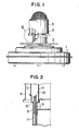
- the combustion apparatus comprises a fuel tank 1, a heat insulation plate 2 mounted on the fuel tank 1 and a combustion cylinder 3 disposed above the heat insulatin plate 2 which is in the form of a triple cylinder.
- the combustion cylinder 3 is partly shown in section, and comprises cylindrical-shaped inner and outer flame tubes 4 and 5, a cylindrical-shaped outer tube 6 surrounding the outer side of the outer flame tube 5 and cylindrical-shaped inner and outer wick guide tubes 7 and 8 which respectively include fire grates 9 and 10 for supporting the lower ends of the inner and outer flame tubes 7 and 8, respectively.
- Reference numeral 11 designates a wick which is movable between the inner and outer wick guide tubes 7 and 8 and is adapted to have its upper end extend into a combustion chamber 12 defined between the inner and outer flame tubes 4 and 5 for vaporization and combustion of fuel.
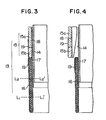
- the wick 11 is shown in vertical section, and comprises a primary cylindrical-shaped wick 13, an auxiliary cylindrical-shaped wick 14 and a vaporization section 15 which includes a sylindrical vaporizing portion 15a and a second vaporizing portion 15b connected to the lower end portion of the portion 15a.
- the second vaporizing portion 15b consists of woven fabrics of glass fibres.
- Reference numeral 16 designates a cylindrical-shaped draw-up member made of fabrics such as of cotton, staple fibres or polypropylene
- numeral 17 designates a second cylindrical isolation body which is formed of stainless steel sheet having a thickness of 0.2 mm in this embodiment and serves also as metal fitting for securement of the wick.
- the auxiliary wick 14 is supported on the inner peripheral surface of the second isolation body 17 and is constructed such that the lower end thereof is positioned above the fuel surface, as shown by broken line Ll - Ll', during combustion and is dipped in the fuel when fire is extinguished by lowering the wick from the position as shown in Figure 2 (and is dipped to the position as shown by broken line L2 - L2" upon extinguishment of the fire) and such that the upper end thereof extends upward beyond the upper end of the vaporizing portion 15a upon extinguishment of the fire.
- the draw-up member 16 is supported on lower, outer peripheral surface of the second isolation body 17.
- Reference numeral 18 designates a first cylindrical isolation body, on the outer peripheral surface of which is supported the vaporization section 15.
- the first and second isolaiton bodies 18 and 17 are detachably connected to each other as by bayonet joint, so that the vaporization section 15 is releasably connected to the upper portion of the draw-up member 16.
- Reference numeral 19 designates an adhesive tape in the form of sheet.
- the first and second isolation bodies 18 and 17 constitutes a cylinder as shown in Figure 5 which is secured to the wick to form a releasable unit.
- the second isolation body 17 is formed at its upper peripheral side surface with projections 20 which passes through guides 21 formed on the lower peripheral side surface of the first isolation body 18 to be positioned in apertures 22 formed in the first isolation body 18 in the circumferential direction.
- the vaporizing portion 15a is formed of a paper-like sheet (hereinafter, referred to as ceramic wick) of silica-alumina heat resistant inorganic fibres, so that its durability against inferior kerosene is greatly improved as compared with a wick (hereinafter, referred to as glass wick) made of a knitted braid of glass fibres which has been conventionally used.
- ceramic wick paper-like sheet
- glass wick made of a knitted braid of glass fibres which has been conventionally used.
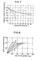
- Figure 7 shows a result of measurements in which changes in amounts of burned fuel were measured when kerosene mixed with 0.1 % of salad oil was burned in actual combustion apparatus which incorporated a wick of the embodiment of the invention (ceramic wick) and a conventional wick (glass wick), respectively.
- the ceramic wick according to the embodiment of the invention exhibits a substantially superior characeristics (as shown by solid line) as compared with the conventional wick (as shown by broken line).
- the vaporizing portion 15a is formed by manufacturing short fibres of ceramic in a manner like paper and binding the resulting product by means of a binder and the short fibres in the resulting vaporizing portion are closely packed to provide a large number of fine and uniform capillary tubes, all of which are capable of drawing fuel up.
- the vaporizing portion consisting of a conventional glass wick is constructed such that long fibres get coarsely interwined to provide fibrous lattices, along which fuel is drawn up, and other spaces in the glass wick except for the fibrous lattices do not contain any fuel. This is satisfied by amounts of fuel contained per unit volume, as shown in Table 1.
- the amount of fuel contained per unit volume is scarcely varied whether the height above the fuel surface (hereinafter, referred to as "draw-up height") is 20 mm or 90 mm.
- draw-up height the amount of fuel contained per unit volume is reduced the more the draw-up height, and is approximately half that in the case of the ceramic wick when the draw-up height is 90 mm.
- the surface of the vaporizing portion 15a is suffused with fuel to permit the end surface thereof to serve as a vaporizing surface, and an amount of fuel contained per unit volume is large in the inside of the vaporizing portion 15a where the temperature is lower than at the surface such that tar is hard to be produced, thereby eliminating reduction in the rate of combustion.
- the glass wick In the glass wick, spaces defined between fibres are large, and the amount of fuel contained per unit volume is not so much at the surface of the vaporizing portion. Accordingly, fuel vaporizes at the surfaces of fibres inside the vaporizing portion, at which surfaces tar-like substances are produced. Thus fuel is prevented from being supplied to the area of the vaporizing portion above that area where the tar-like substances are produced, so that reduction in the rate of combustion is liable to be caused. In this manner, the use of the ceramic wick greatly improves durability to inferior kerosene as compared with conventional glass wicks and the like.
- the auxiliary wick 14 is provided in order to speed up fire spreading over the entire top of the vaporization portion after lighting.
- Conventional wicks consisting of glass fibres are thin in thickness at or near the tip end thereof and diverge at the tip ends thereof so as to increase vaporizing surface areas, so that an amount of fuel contained in the tip end portions is small to cause rapid fire spreading after lighting.
- the ceramic wick according to the embodiment of the invention however, an amount of fuel contained per unit volume is substantial near the tip end of the vaporizing portion 15a, so that rapid temperature rise is hard to be produced after lighting, thus taking much time for fire spreading. Therefore, the auxiliary wick 14 is provided which includes glass fibres or fire resistant fibres at the tip end thereof for rapid fire spreading.
- the tip end of the auxiliary wick 14 extends slightly beyond the tip end of the vaporizing porton 15a whereby after lighting a large flame is formed above the vaporizing portion 15a to ensure fire spreading over the tip end of the vaporizing porton 15a.
- the lower end of the auxiliary wick 14 is positoned above the fuel surface during burning, and is dipped in the body of fuel after fire is put out by lowering the wick.
- fuel is drawn up through the wick 13 and the auxiliary wick 14 after fire is put out while transfer of fuel therebetween is prevented by the first and second isolation bodies 18 and 17 such that fuel for vaporization is drawn up through the wick 13 and fuel required for fire lighting and fire spreding is independently drawn up through the auxiliary wick 14.
- Figure 9 shows changes in the peak value of the amount of carbon monoxide at the time of fire lighting when the above noted extend of the auxiliary wick 14 was varied. As seen from the drawing, the greater the peak value the larger the extend of the auxiliary wick 14. It is to be noted that Figure 9 shows only the peak values and periods of time during which carbon monoxide was produced were quite short. rhereofore, the peak value not much exceeding 500 ppm is believed not to present any problem in actual use. In the embodment of the invention, production of soot (area of oblique lines in Figure 9) was observed when the above noted extend of the auxiliary wick 14 was 5 mm and more. While the peak value of carbon monoxide was low when the above noted extend was 1 mm and less, carbon monoxide was prduced at a relatively high level for a long period of time to disadvantageously provide a large amount thereof as a whole.
- Figure 10 shows changes in periods of time required for fire spreaidng when the above noted extend of the auxiliary wick 14 was varied.
- the extent was 1 mm and more, fire spreading was completed within ten seconds and less while it took a good long time when the extent was 1 mm and less. This is because flames formed above the auxiliary wick 14 after fire lighting were small when the above noted extend was small, so that an adequate temperature rise and an increase in the amount of vaporized fuel in the circumferential direction of the auxiliary wick 14 could not be brought about to thereby cause odor, soot and carbon monoxide to be unfavorably produced in large quantities.
- the extent over which the auxiliary wick 14 extends beyond the to end of the vaporizing portion 15a is preferably in the range of 1 mm to 5 mm.
- the embodiment of the invention is greatly advantageous in that extremely simple replacement can be accomplished by the constitution in which the vaporization section 15 and the draw-up member 16 are detachably connected to each other. More specifically, no matter how superior durability the vaporization sectoin 15 has to inferior kerosene, it is impossible to eliminate production of tar to the utmost. According to the embodiment of the invention, besides improving the durability of the wick as much as possible, only the vaporization section 15 can be replaced in a simple operation in case the wick is deteriorated.
- Figure 11 shows a manner in which the vaporization section 15 is replaced by a new one.
- the tip end of the vaporizing portion 15a is formed diametrically thereof with at least two recesses 23.
- the first isolation body 18 is provided with latch portoins 24 which are disposed adjacent the recesses 23 of the vaporizing portion 15a and are smaller than the recesses 23.
- the first isolation body 18 is further provided with bent portions 25 which are directed toward the vaporization section 15.
- Reference numeral 26 designates a jig which is used for replacement of the wick and is formed at its tip ends with latches 27. In mounting the vaporization section 15 on the apparatus, the projections 20 are moved to the leftward ends of the apertures 22 along the guides 21.
- the latches 27 of the jig 26 are inserted into the latch portions 24 for rotation thereof in an arrow direction a in Figure 11 whereupon the projections 20 are moved in the aperture 22 to be fixed at the rightward ends thereof.
- the latches 27 of the jig 26 are inserted into the latch portions 24 for rotation of the first isolation body 18 in the direction b in Figure 11 whereupon the projections 20 are moved to the leftward ends of the apertures 22.
- the provision of the latches 27 on the ends of the jig 26 enables readily removing the vaporization section 15 only by engaging the latches 27 with the latch portions 24 and lifting the jig 26 without the necessity of touching the wick soiled with fuel.
- the latch portions 24 formed on the bent portions 25 serve to engage with the jig 26, and may be notches 24 as shown in Figures 12A and 12B in place of apertures provided that the latches 27 on the jig 26 take suitable configurations.
- Another feature of the embodiment of the invention resides in that at least one of the recesses 23 diametrically provided on the tip end of the vaporization section 15 is disposed in facing relationship with a lighting device 28 provided near the vaporization section to thereby improve the lighting characteristics of the apparatus. More specifically, if the recesses 23 were not disposed on the tip end of the vaporization- section 15 in facing relationship with the lighting device 28, the tip end of the vaporization section 15 where a large amount of fuel is contained would be difficult to be subject to rapid temperature rise even when the auxiliary wick 14 is lighted.
- Figure 13 shows another manner in which the vaporization section 15 is replaced by a new one.
- the first isolation body 18 is provided at its tip end with at least two projections 30 which are disposed diametrically of the isolation body 18 and are bent toward the vaporization section 15 to provide bent portions 25 and latch portions 24.
- Replacement of the vaporization section by a new one is performed in a manner like the manner as shown in Figure 11.
- the configurations of the latch portions 24 and the latches 27 may be suitably selected.
- the embodiment of the invention as shown in Figure 13 has a feature in that the embodiment of the invention as shown in Figure 13 has a feature in that the height x of the projections 30 relative to the tip end of the first isolation body 18 or the second isolation body 17 is smaller than the height y of the auxiliary wick 14 relative to the top end of the first isolation body 18 or the second isolation body 17 to thereby promote fire spreading after fire lighting.
- the height x of the projctions 30 were larger than the height y of the auxiliary wick 14, flames would be cooled down due to the large heat capacity of the projections 30 to impede rapid fire spreading.
- the arrangement in which the projections 30 are bent toward the wick is for the sake of lowering the top ends of the projections 30 as far as possible. Since pulling and rotating forces are exerted on the projections 30 by engaging the latches 30 of the jig 26 therewith, the projections 30 need to have a relatively large strength and accordingly become large in size. Thus it is difficult to lower the top ends of the projections 30 below the top ends of the auxiliary wick 14 while extending the projections 30 upward, as shown in Figure 14, since the fire spreading characteristics will be marred when x > y.
- the projections 30 are bent toward the wick 13 to limit the hegiht of the top ends of the projections 30 above the top end of the first isolation body 18 or the second isolation body 17 to the thickness of the latches 27 of the jig 26 or near, so that the fire spreading characteristics of the apparatus is not marred to present rapid fire spreading at all times while the strength of the projections 30 is maintained.
- the wick according to the present invention makes it possible to suppress production of tar-like substances and eliminate the resulting reduction in the rate of combustion, and is greatly improved in its durability to inferior kerosene as well as in its fire spreading characteristics to maintain the latter for a long time, thereby reducing odor, soot and carbon monoxide produced due to degradation of fire spreading characteristics.
- tar-like substances are deposited on the vaporization section after a long time use to render same unfit for use, replacement of only the vaporization section will suffice since it is detachably connected to the draw-up member. Such replacement is low in cost and is readily and cleanly performed without the necessity of removing any elements constituting the apparatus and touching the solid wick.
Landscapes
- Engineering & Computer Science (AREA)
- Chemical & Material Sciences (AREA)
- Combustion & Propulsion (AREA)
- Mechanical Engineering (AREA)
- General Engineering & Computer Science (AREA)
- Wick-Type Burners And Burners With Porous Materials (AREA)
Applications Claiming Priority (6)
| Application Number | Priority Date | Filing Date | Title |
|---|---|---|---|
| JP56140199A JPS5843314A (ja) | 1981-09-04 | 1981-09-04 | 灯芯 |
| JP140199/81 | 1981-09-04 | ||
| JP187585/81 | 1981-11-20 | ||
| JP56187585A JPS5888509A (ja) | 1981-11-20 | 1981-11-20 | 灯芯 |
| JP57004063A JPS58123007A (ja) | 1982-01-14 | 1982-01-14 | 灯芯 |
| JP4063/82 | 1982-01-14 |
Publications (1)
| Publication Number | Publication Date |
|---|---|
| EP0076568A1 true EP0076568A1 (fr) | 1983-04-13 |
Family
ID=27276092
Family Applications (1)
| Application Number | Title | Priority Date | Filing Date |
|---|---|---|---|
| EP82304630A Withdrawn EP0076568A1 (fr) | 1981-09-04 | 1982-09-02 | Mèche pour la combustion du combustible liquide |
Country Status (2)
| Country | Link |
|---|---|
| EP (1) | EP0076568A1 (fr) |
| AU (1) | AU8800182A (fr) |
Citations (4)
| Publication number | Priority date | Publication date | Assignee | Title |
|---|---|---|---|---|
| DE136431C (fr) * | ||||
| DE74924C (de) * | A. mager in Berlin, Lützowstr. 68 | Lampendocht | ||
| US1065834A (en) * | 1912-05-25 | 1913-06-24 | Manning Pike | Liquid-fuel burner. |
| DE1085114B (de) * | 1955-07-20 | 1960-07-14 | Ir Alexander Leendert Thomee | Flachdochtbrenner mit einem Saug- und einem Brenndocht |
-
1982
- 1982-09-02 EP EP82304630A patent/EP0076568A1/fr not_active Withdrawn
- 1982-09-03 AU AU88001/82A patent/AU8800182A/en not_active Abandoned
Patent Citations (4)
| Publication number | Priority date | Publication date | Assignee | Title |
|---|---|---|---|---|
| DE136431C (fr) * | ||||
| DE74924C (de) * | A. mager in Berlin, Lützowstr. 68 | Lampendocht | ||
| US1065834A (en) * | 1912-05-25 | 1913-06-24 | Manning Pike | Liquid-fuel burner. |
| DE1085114B (de) * | 1955-07-20 | 1960-07-14 | Ir Alexander Leendert Thomee | Flachdochtbrenner mit einem Saug- und einem Brenndocht |
Also Published As
| Publication number | Publication date |
|---|---|
| AU8800182A (en) | 1983-03-10 |
Similar Documents
| Publication | Publication Date | Title |
|---|---|---|
| EP0053192B1 (fr) | Meche pour bruleur a combustible liquide | |
| EP0062910B1 (fr) | Mèche pour un brûleur | |
| EP0076568A1 (fr) | Mèche pour la combustion du combustible liquide | |
| EP0049865B1 (fr) | Dispositif de combustion pour combustible liquide | |
| CA1172156A (fr) | Appareil fonctionnant au combustible liquide | |
| EP0042171B1 (fr) | Dispositif de combustion pour combustible liquide | |
| JPS58104408A (ja) | 灯芯 | |
| EP0064559B1 (fr) | Bruleur de combustible liquide avec meche | |
| JPS6324325Y2 (fr) | ||
| JPS5888509A (ja) | 灯芯 | |
| JPS5843314A (ja) | 灯芯 | |
| JPS58182008A (ja) | 液体燃料燃焼装置 | |
| US20030215763A1 (en) | Wick for a candle/lamp | |
| JPS58160712A (ja) | 灯芯 | |
| JPS5886312A (ja) | 液体燃料燃焼装置 | |
| JPS6334361B2 (fr) | ||
| JPH0313484B2 (fr) | ||
| JPS6333607B2 (fr) | ||
| JPS5843315A (ja) | 灯芯 | |
| JPS6222728Y2 (fr) | ||
| JPH0311526Y2 (fr) | ||
| JPS5833006A (ja) | 燃焼芯 | |
| JPS5813911A (ja) | 燃焼芯 | |
| JPS5878007A (ja) | 燃焼芯 | |
| JPS5849762B2 (ja) | セキユネンシヨウキ |
Legal Events
| Date | Code | Title | Description |
|---|---|---|---|
| PUAI | Public reference made under article 153(3) epc to a published international application that has entered the european phase |
Free format text: ORIGINAL CODE: 0009012 |
|
| AK | Designated contracting states |
Designated state(s): DE FR GB IT |
|
| 17P | Request for examination filed |
Effective date: 19831007 |
|
| STAA | Information on the status of an ep patent application or granted ep patent |
Free format text: STATUS: THE APPLICATION IS DEEMED TO BE WITHDRAWN |
|
| 18D | Application deemed to be withdrawn |
Effective date: 19841008 |
|
| RIN1 | Information on inventor provided before grant (corrected) |
Inventor name: HIRATA, YASUSHI Inventor name: ISHIKAWA, KATSUHIKO Inventor name: OGINO, TOSHIRO Inventor name: UNO, KATSUHIKO |