EP0076835B2 - Disposition de conduits pour pulverisateur electrostatique - Google Patents
Disposition de conduits pour pulverisateur electrostatique Download PDFInfo
- Publication number
- EP0076835B2 EP0076835B2 EP82901314A EP82901314A EP0076835B2 EP 0076835 B2 EP0076835 B2 EP 0076835B2 EP 82901314 A EP82901314 A EP 82901314A EP 82901314 A EP82901314 A EP 82901314A EP 0076835 B2 EP0076835 B2 EP 0076835B2
- Authority
- EP
- European Patent Office
- Prior art keywords
- ducts
- powder
- loops
- ductwork
- ductwork according
- Prior art date
- Legal status (The legal status is an assumption and is not a legal conclusion. Google has not performed a legal analysis and makes no representation as to the accuracy of the status listed.)
- Expired - Lifetime
Links
- 239000000843 powder Substances 0.000 claims abstract description 35
- 239000000463 material Substances 0.000 claims abstract description 7
- 239000004020 conductor Substances 0.000 claims abstract description 3
- 239000010410 layer Substances 0.000 claims description 4
- 239000004411 aluminium Substances 0.000 claims description 2
- 229910052782 aluminium Inorganic materials 0.000 claims description 2
- XAGFODPZIPBFFR-UHFFFAOYSA-N aluminium Chemical compound [Al] XAGFODPZIPBFFR-UHFFFAOYSA-N 0.000 claims description 2
- 239000011247 coating layer Substances 0.000 claims 1
- 239000004033 plastic Substances 0.000 description 3
- 229920003023 plastic Polymers 0.000 description 3
- 238000004040 coloring Methods 0.000 description 2
- 229910052751 metal Inorganic materials 0.000 description 2
- 239000002184 metal Substances 0.000 description 2
- 230000015572 biosynthetic process Effects 0.000 description 1
- 239000011248 coating agent Substances 0.000 description 1
- 238000000576 coating method Methods 0.000 description 1
- 239000006185 dispersion Substances 0.000 description 1
- 239000011888 foil Substances 0.000 description 1
- 238000005755 formation reaction Methods 0.000 description 1
- 238000000034 method Methods 0.000 description 1
- 238000012986 modification Methods 0.000 description 1
- 230000004048 modification Effects 0.000 description 1
- 238000012856 packing Methods 0.000 description 1
- 239000002985 plastic film Substances 0.000 description 1
- 229920006255 plastic film Polymers 0.000 description 1
- 239000011241 protective layer Substances 0.000 description 1
Images




Classifications
-
- B—PERFORMING OPERATIONS; TRANSPORTING
- B05—SPRAYING OR ATOMISING IN GENERAL; APPLYING FLUENT MATERIALS TO SURFACES, IN GENERAL
- B05B—SPRAYING APPARATUS; ATOMISING APPARATUS; NOZZLES
- B05B5/00—Electrostatic spraying apparatus; Spraying apparatus with means for charging the spray electrically; Apparatus for spraying liquids or other fluent materials by other electric means
- B05B5/025—Discharge apparatus, e.g. electrostatic spray guns
- B05B5/047—Discharge apparatus, e.g. electrostatic spray guns using tribo-charging
Definitions
- the present invention relates to ductwork for an electrostatic sprayer, as disclosed in SE-B-371 967, according to the precharacterizing portion of claim 1.
- the SE-B-371 967 discloses a ductwork for an electrostatic sprayer, wherein the powder becomes electrostatically charged by a rotating disc within a fan housing.
- the powder is thereafter fed through the non-conducting ductwork, which is wound in several successive loops, the centre planes of which extending substantially in the direction of the powder supply. Finally the powder is ejected through a nozzle.
- the loops of the individual ducts are arranged close to each other to form bundles the axes of which are essentially perpendicular to the supply direction of the powder.
- This arrangement makes it possible that the course of the ducts as loops, which is important for the quality of the electrostatic charge of the powder, can be maintained also if a great number of ducts is provided.
- By reversing the transportation direction of the powder in the loops the contact of the powder with the internal walls of the ducts is enhanced, so that effective use is made of the long paths within the ducts and their connection to a power source for charging the powder.
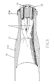
- the plate 5 is provided on its outer circumferential surface with a recess, in which a seal in the form of an O-ring 3A, for example, is arranged to rest between the core 3 and a sleeve- type connection 12 which is designed to be used for connecting the electrostatic sprayer 1 to a powder-supplying hose or the like.
- the other ends of the ducts 2 i.e. the ends which are furthest forwards, viewed in the transportation direction of the powder, are accommodated in another core 13.
- This other core 13, which is expediently also made of a plastic material, similarly has passage holes 14 distributed in a circle around its periphery, corresponding in number to the number of charging ducts 2 and adapted to the respective charging ducts 2, as can be seen in Figure 3.
- the said core 13 is supported by a front sleeve- type connecting part 15, which is equipped with a threaded part 15A designed to be used for connecting the electrostatic sprayer to a dispersing nozzle.
- the charging ducts 2, the connecting parts 12, 15 and the other associated parts can be enclosed in a preferably box-shaped casing 16, which is formed in the example shown here of two parts 16A and 16B with respective joining surfaces disposed extending in the longitudinal direction of the electrostatic sprayer 1.
- the ends 16C and 16D of the casing 16 are drawn in somewhat so that the connecting parts 12, 15, which can be provided, for example, with their own respective stop-type parts 12A and 15B, can be accommodated in their respective ends 16C, 16D of the casing 16.
- a fixing 17 is expediently attached to the casing 16 and is designed to be used when the electrostatic sprayer 1 is to be supported on and manipulated via a manipulator, for example, or a similar device.
- One characteristic feature of the present invention is the way in which the charging ducts 2 are curved.
- FIG 5 shows an arrangement of the loops 18 similar to that which is shown in Figure 4 except that certain loops 18 are given differently-sized curvature diameters.
- Figure 6 shows an embodiment where a plurality of loops 18 disposed transverse to the transportation direction of the powder form groups 18' of loops 18 which are displaced sideways relative to each other, viewed in the transportation direction, but are still arranged to form a continuous powder duct 2.
- an electrically-conducting layer of metal foil may be wrapped around the curved ducts 2.
- a protective layer of plastic film such as heat- shrunk film 20, for example, may also be disposed around the charging ducts 2 when these are made into a single unit, as shown in Figure 1.
- the functioning of the electrostatic sprayer as described above, which can be used, for example, for charging colouring powder is as follows.
- the rear end 12 of the electrostatic sprayer 1 is connected by means of a hose to a powder container so that colouring powder, for example, can be transported with the aid of a stream of air to the electrostatic sprayer 1 and through the ducts 2.
- the powder comes into close contact with the internal walls of the ducts 2, and due to the fact that the ducts 2 are connected to a power source, is charged effectively over the whole of the surface of the powder. Due to the fact that the powder is flung towards the internal walls of the respective ducts 2 and that the loops 18 change direction, virtually all the powder comes into contact with the walls and is charged.
- the charged powder is then supplied through the connecting part 15 and onwards out of the electrostatic sprayer 1 through the dispersion nozzle and, due to the fact that it has been charged, it strives to seek out the object which it is desired to coat with the powder. In particular, sites on the object which are hard to reach can be coated effectively with the powder.
Landscapes
- Electrostatic Spraying Apparatus (AREA)
- Application Of Or Painting With Fluid Materials (AREA)
- Developing Agents For Electrophotography (AREA)
- Photoreceptors In Electrophotography (AREA)
- Nozzles (AREA)
- Elimination Of Static Electricity (AREA)
- Infusion, Injection, And Reservoir Apparatuses (AREA)
- Fats And Perfumes (AREA)
Claims (8)
Applications Claiming Priority (2)
| Application Number | Priority Date | Filing Date | Title |
|---|---|---|---|
| SE8102606A SE446826B (sv) | 1981-04-24 | 1981-04-24 | Pulverspruta med elektrostatisk laddningsformaga bestaende av langstreckta krokta laddningskanaler vilka krokts att bilda loopar eller vagor anordnade i ett flertal grupper |
| SE8102606 | 1981-04-24 |
Publications (3)
| Publication Number | Publication Date |
|---|---|
| EP0076835A1 EP0076835A1 (fr) | 1983-04-20 |
| EP0076835B1 EP0076835B1 (fr) | 1986-07-16 |
| EP0076835B2 true EP0076835B2 (fr) | 1990-09-05 |
Family
ID=20343667
Family Applications (1)
| Application Number | Title | Priority Date | Filing Date |
|---|---|---|---|
| EP82901314A Expired - Lifetime EP0076835B2 (fr) | 1981-04-24 | 1982-04-22 | Disposition de conduits pour pulverisateur electrostatique |
Country Status (10)
| Country | Link |
|---|---|
| US (1) | US4597534A (fr) |
| EP (1) | EP0076835B2 (fr) |
| JP (1) | JPS58500697A (fr) |
| AT (1) | ATE20706T1 (fr) |
| AU (1) | AU8390482A (fr) |
| DE (1) | DE3271997D1 (fr) |
| DK (1) | DK155425C (fr) |
| NO (1) | NO158525C (fr) |
| SE (1) | SE446826B (fr) |
| WO (1) | WO1982003573A1 (fr) |
Families Citing this family (17)
| Publication number | Priority date | Publication date | Assignee | Title |
|---|---|---|---|---|
| SE451954B (sv) * | 1985-10-18 | 1987-11-09 | Icab Ind Coating Ab | Pulverspruta med spiralformigt krokta laddningskanaler och en diffusoranordning placerad i handtagsdelen |
| US4884752A (en) * | 1987-11-18 | 1989-12-05 | The Deilbiss Company | Electrostatic paint spray system with dual voltage isolating paint reservoirs |
| DE59208832D1 (de) * | 1992-10-21 | 1997-10-02 | Piatti Alfredo Ag | Verfahren und Vorrichtung zum Reinigen von Oberflächen, insbesondere von Mauerwerk |
| EP0627265B1 (fr) * | 1993-06-02 | 1998-01-21 | Matsuo Sangyo Co., Ltd. | Pistolet à charge tribo-électrique |
| US5395046A (en) * | 1993-10-25 | 1995-03-07 | Nordson Corporation | Hand-held spray gun with replaceable handle |
| SE503654C2 (sv) * | 1994-11-09 | 1996-07-29 | Nordson Sverige Ab | Sätt och anordning för att belägga en bana t ex en kraftkabel med pulver |
| TW340063B (en) * | 1996-04-25 | 1998-09-11 | Kao Corp | Electrostatic powder coating gun |
| US6492705B1 (en) | 1996-06-04 | 2002-12-10 | Intersil Corporation | Integrated circuit air bridge structures and methods of fabricating same |
| JP3328555B2 (ja) * | 1997-08-19 | 2002-09-24 | 株式会社日清製粉グループ本社 | 微粉体の帯電量制御方法および装置ならびに微粉体の散布方法および装置 |
| JP2000093851A (ja) * | 1998-09-25 | 2000-04-04 | Nippon Parkerizing Co Ltd | 粉体荷電装置及び方法並びに粉体塗装装置及び方法 |
| US20040011901A1 (en) * | 2000-07-10 | 2004-01-22 | Rehman William R. | Unipolarity powder coating systems including improved tribocharging and corona guns |
| US20030038193A1 (en) * | 2000-07-11 | 2003-02-27 | Rehman William R. | Unipolarity powder coating systems including improved tribocharging and corona guns |
| US6645300B2 (en) | 2000-07-11 | 2003-11-11 | Nordson Corporation | Unipolarity powder coating systems including improved tribocharging and corona guns |
| AU2002219696A1 (en) * | 2002-01-10 | 2003-07-24 | Samsung Electronics Co., Ltd. | Apparatus for electrifying particle, apparatus for scattering particle |
| US20040159282A1 (en) * | 2002-05-06 | 2004-08-19 | Sanner Michael R | Unipolarity powder coating systems including improved tribocharging and corona guns |
| AU2005202150A1 (en) * | 2004-06-21 | 2006-01-12 | Air Liquide Australia Limited | An Apparatus for Inerting the Headspace of a Container |
| DE102019125162B3 (de) * | 2019-09-18 | 2021-03-04 | Bader Pulverbeschichtung Gmbh | Vorrichtung und Sprühkabine zum Pulverbeschichten mittels triboelektrischer Aufladung |
Family Cites Families (16)
| Publication number | Priority date | Publication date | Assignee | Title |
|---|---|---|---|---|
| US2739838A (en) * | 1955-01-17 | 1956-03-27 | Sedlacsik John | Paint spray apparatus |
| NL269158A (fr) * | 1960-10-17 | |||
| FR1330178A (fr) * | 1962-04-25 | 1963-06-21 | Sames Mach Electrostat | Perfectionnements aux têtes de pulvérisation électrostatique |
| GB1104461A (en) * | 1963-09-27 | 1968-02-28 | Sames Mach Electrostat | Pneumatic atomizer for spraying liquids |
| GB1153868A (en) * | 1966-04-20 | 1969-05-29 | Inducal Berlin Veb | An improved Electrostatic High-Pressure Spray Gun Assembly |
| GB1236448A (en) * | 1967-11-24 | 1971-06-23 | Arnim Karl Schimmer | A static converter for supplying a high direct voltage to a discharge electrode |
| FR2082706A5 (fr) * | 1970-03-24 | 1971-12-10 | Ransburg Sa | |
| DE2059594C3 (de) * | 1970-07-31 | 1973-09-20 | Hajtomue Es Felvonogyar, Budapest | Vorrichtung zum elektrostatischen Aufstäuben von Farbstoffen, Pulver,Faserstoffen u.dgl |
| DE2135968C2 (de) * | 1971-07-19 | 1981-10-08 | Hugo 7400 Tübingen Brennenstuhl | Verfahren zum Abstoßen von Teilchen von einer Unterlage sowie Vorrichtung zur Durchführung des Verfahrens |
| SE371967B (fr) * | 1972-05-15 | 1974-12-09 | Tri Innovations Ab | |
| SU504560A1 (ru) * | 1972-11-30 | 1976-02-28 | Институт механики металлополимерных систем АН БССР | Электростатический пистолет-распылитель порошкообразных материалов |
| GB1482084A (en) * | 1973-11-01 | 1977-08-03 | Nat Res Dev | Electrostatic powder deposition |
| US4139155A (en) * | 1977-05-25 | 1979-02-13 | Nordson Corporation | Electrostatic spray gun with isolating paint conduit |
| JPS54145744A (en) * | 1978-05-09 | 1979-11-14 | Onoda Cement Co Ltd | Device for charging powder electrically |
| NL187729C (nl) * | 1980-01-04 | 1992-01-02 | Icab Ind Coating Ab | Elektrostatische poederspuit. |
| JPS6224135A (ja) * | 1985-07-25 | 1987-02-02 | Yazaki Corp | ガス警報器 |
-
1981
- 1981-04-24 SE SE8102606A patent/SE446826B/sv not_active IP Right Cessation
-
1982
- 1982-04-22 AT AT82901314T patent/ATE20706T1/de not_active IP Right Cessation
- 1982-04-22 WO PCT/SE1982/000129 patent/WO1982003573A1/fr not_active Ceased
- 1982-04-22 AU AU83904/82A patent/AU8390482A/en not_active Abandoned
- 1982-04-22 EP EP82901314A patent/EP0076835B2/fr not_active Expired - Lifetime
- 1982-04-22 US US06/790,635 patent/US4597534A/en not_active Expired - Fee Related
- 1982-04-22 DE DE8282901314T patent/DE3271997D1/de not_active Expired
- 1982-04-22 JP JP57501380A patent/JPS58500697A/ja active Granted
- 1982-12-23 DK DK571082A patent/DK155425C/da not_active IP Right Cessation
- 1982-12-27 NO NO82824381A patent/NO158525C/no unknown
Also Published As
| Publication number | Publication date |
|---|---|
| DK571082A (da) | 1982-12-23 |
| AU8390482A (en) | 1982-11-04 |
| JPS58500697A (ja) | 1983-05-06 |
| DK155425B (da) | 1989-04-10 |
| NO824381L (no) | 1982-12-27 |
| ATE20706T1 (de) | 1986-08-15 |
| DK155425C (da) | 1989-10-16 |
| EP0076835B1 (fr) | 1986-07-16 |
| JPH0379067B2 (fr) | 1991-12-17 |
| SE446826B (sv) | 1986-10-13 |
| WO1982003573A1 (fr) | 1982-10-28 |
| SE8102606L (sv) | 1982-10-25 |
| DE3271997D1 (en) | 1986-08-21 |
| NO158525C (no) | 1988-09-28 |
| NO158525B (no) | 1988-06-20 |
| US4597534A (en) | 1986-07-01 |
| EP0076835A1 (fr) | 1983-04-20 |
Similar Documents
| Publication | Publication Date | Title |
|---|---|---|
| EP0076835B2 (fr) | Disposition de conduits pour pulverisateur electrostatique | |
| KR100265911B1 (ko) | 마찰 전기 파우더 스프레이 건 | |
| GB2066703A (en) | Electrostatic powder sprayer | |
| FI64059C (fi) | Foerfarande och anordning foer kontinuerlig elektrogasdynamiskbelaeggning av en serie arbetsstycken | |
| US4886215A (en) | Hand operated powder spray pistol | |
| EP0173420A2 (fr) | Pistolet-pulvérisateur de poudre ajustable | |
| US4072129A (en) | Electrostatic powder deposition | |
| US4316582A (en) | Device for painting by electrostatic powder spraying | |
| US3550852A (en) | Methods and apparatus for applying powder coatings to articles | |
| US4660772A (en) | Electrostatic powder spray gun nozzle | |
| US4772982A (en) | Powder charging apparatus and electrostatic powder coating apparatus | |
| JPH02503648A (ja) | 導電性被覆液用吹付け被覆装置 | |
| WO1985001894A1 (fr) | Procede a utiliser avec une buse de pulverisation et dispositif pour realiser ce procede | |
| JPS62163758A (ja) | 調整可能なフラツトパタ−ン粉体スプレガン | |
| EP0230723A2 (fr) | Appareil pour le chargement de poudre et de revêtement électrostatique à l'aide de cette poudre | |
| TW340063B (en) | Electrostatic powder coating gun | |
| SE446825B (sv) | Pulverspruta med oregelbundet krokta laddningskanaler | |
| SU1069863A1 (ru) | Трибоэлектрический распылитель | |
| US3750949A (en) | Spray gun for pulverulent material entrained in a gaseous stream | |
| JPH07874A (ja) | 静電塗装用摩擦帯電ガン | |
| JPS5946797A (ja) | 管路式除電器 | |
| JPS641188B2 (fr) | ||
| CA1170034A (fr) | Diffuseur de poudre | |
| JPS5857296A (ja) | 管路式除電器 | |
| JPH11342912A (ja) | 部品供給方法および装置 |
Legal Events
| Date | Code | Title | Description |
|---|---|---|---|
| PUAI | Public reference made under article 153(3) epc to a published international application that has entered the european phase |
Free format text: ORIGINAL CODE: 0009012 |
|
| 17P | Request for examination filed |
Effective date: 19821223 |
|
| AK | Designated contracting states |
Designated state(s): AT BE CH DE FR GB LI LU NL |
|
| GRAA | (expected) grant |
Free format text: ORIGINAL CODE: 0009210 |
|
| AK | Designated contracting states |
Kind code of ref document: B1 Designated state(s): AT BE CH DE FR GB LI LU NL |
|
| REF | Corresponds to: |
Ref document number: 20706 Country of ref document: AT Date of ref document: 19860815 Kind code of ref document: T |
|
| REF | Corresponds to: |
Ref document number: 3271997 Country of ref document: DE Date of ref document: 19860821 |
|
| ET | Fr: translation filed | ||
| PLBI | Opposition filed |
Free format text: ORIGINAL CODE: 0009260 |
|
| PG25 | Lapsed in a contracting state [announced via postgrant information from national office to epo] |
Ref country code: LU Free format text: LAPSE BECAUSE OF NON-PAYMENT OF DUE FEES Effective date: 19870430 |
|
| 26 | Opposition filed |
Opponent name: VEB INFRAROT-ANLAGEN ORANIENBURG Effective date: 19870416 |
|
| NLR1 | Nl: opposition has been filed with the epo |
Opponent name: VEB INFRAROT - ANLAGEN ORANIENBURG |
|
| PGFP | Annual fee paid to national office [announced via postgrant information from national office to epo] |
Ref country code: LU Payment date: 19900409 Year of fee payment: 9 |
|
| PGFP | Annual fee paid to national office [announced via postgrant information from national office to epo] |
Ref country code: AT Payment date: 19900420 Year of fee payment: 9 |
|
| PGFP | Annual fee paid to national office [announced via postgrant information from national office to epo] |
Ref country code: NL Payment date: 19900430 Year of fee payment: 9 |
|
| PUAH | Patent maintained in amended form |
Free format text: ORIGINAL CODE: 0009272 |
|
| STAA | Information on the status of an ep patent application or granted ep patent |
Free format text: STATUS: PATENT MAINTAINED AS AMENDED |
|
| PGFP | Annual fee paid to national office [announced via postgrant information from national office to epo] |
Ref country code: BE Payment date: 19900822 Year of fee payment: 9 |
|
| 27A | Patent maintained in amended form |
Effective date: 19900905 |
|
| AK | Designated contracting states |
Kind code of ref document: B2 Designated state(s): AT BE CH DE FR GB LI LU NL |
|
| ET3 | Fr: translation filed ** decision concerning opposition | ||
| NLR2 | Nl: decision of opposition | ||
| NLR3 | Nl: receipt of modified translations in the netherlands language after an opposition procedure | ||
| PG25 | Lapsed in a contracting state [announced via postgrant information from national office to epo] |
Ref country code: AT Effective date: 19910422 |
|
| PG25 | Lapsed in a contracting state [announced via postgrant information from national office to epo] |
Ref country code: BE Effective date: 19910430 |
|
| BERE | Be: lapsed |
Owner name: ICAB INDUSTRIAL COATING A.B. Effective date: 19910430 |
|
| PG25 | Lapsed in a contracting state [announced via postgrant information from national office to epo] |
Ref country code: NL Effective date: 19911101 |
|
| NLV4 | Nl: lapsed or anulled due to non-payment of the annual fee | ||
| PGFP | Annual fee paid to national office [announced via postgrant information from national office to epo] |
Ref country code: FR Payment date: 19980312 Year of fee payment: 17 |
|
| PGFP | Annual fee paid to national office [announced via postgrant information from national office to epo] |
Ref country code: GB Payment date: 19980320 Year of fee payment: 17 |
|
| PGFP | Annual fee paid to national office [announced via postgrant information from national office to epo] |
Ref country code: DE Payment date: 19980325 Year of fee payment: 17 |
|
| PGFP | Annual fee paid to national office [announced via postgrant information from national office to epo] |
Ref country code: CH Payment date: 19980403 Year of fee payment: 17 |
|
| PG25 | Lapsed in a contracting state [announced via postgrant information from national office to epo] |
Ref country code: GB Free format text: LAPSE BECAUSE OF NON-PAYMENT OF DUE FEES Effective date: 19990422 |
|
| PG25 | Lapsed in a contracting state [announced via postgrant information from national office to epo] |
Ref country code: LI Free format text: LAPSE BECAUSE OF NON-PAYMENT OF DUE FEES Effective date: 19990430 Ref country code: CH Free format text: LAPSE BECAUSE OF NON-PAYMENT OF DUE FEES Effective date: 19990430 |
|
| GBPC | Gb: european patent ceased through non-payment of renewal fee |
Effective date: 19990422 |
|
| REG | Reference to a national code |
Ref country code: CH Ref legal event code: PL |
|
| PG25 | Lapsed in a contracting state [announced via postgrant information from national office to epo] |
Ref country code: FR Free format text: LAPSE BECAUSE OF NON-PAYMENT OF DUE FEES Effective date: 19991231 |
|
| REG | Reference to a national code |
Ref country code: FR Ref legal event code: ST |
|
| PG25 | Lapsed in a contracting state [announced via postgrant information from national office to epo] |
Ref country code: DE Free format text: LAPSE BECAUSE OF NON-PAYMENT OF DUE FEES Effective date: 20000201 |
|
| PLAB | Opposition data, opponent's data or that of the opponent's representative modified |
Free format text: ORIGINAL CODE: 0009299OPPO |