EP0077763A1 - Zusammengesetztes Teil - Google Patents
Zusammengesetztes Teil Download PDFInfo
- Publication number
- EP0077763A1 EP0077763A1 EP82850198A EP82850198A EP0077763A1 EP 0077763 A1 EP0077763 A1 EP 0077763A1 EP 82850198 A EP82850198 A EP 82850198A EP 82850198 A EP82850198 A EP 82850198A EP 0077763 A1 EP0077763 A1 EP 0077763A1
- Authority
- EP
- European Patent Office
- Prior art keywords
- section
- composite section
- composite
- pipe parts
- box
- Prior art date
- Legal status (The legal status is an assumption and is not a legal conclusion. Google has not performed a legal analysis and makes no representation as to the accuracy of the status listed.)
- Granted
Links
- 239000002131 composite material Substances 0.000 title claims abstract description 52
- 239000006096 absorbing agent Substances 0.000 claims abstract description 12
- 238000013016 damping Methods 0.000 claims abstract description 5
- 239000002184 metal Substances 0.000 claims description 8
- 239000011358 absorbing material Substances 0.000 claims description 6
- 238000010168 coupling process Methods 0.000 claims description 6
- 238000005859 coupling reaction Methods 0.000 claims description 6
- 238000010438 heat treatment Methods 0.000 claims description 4
- 230000008878 coupling Effects 0.000 description 4
- 238000010276 construction Methods 0.000 description 2
- 238000009434 installation Methods 0.000 description 2
- 230000004308 accommodation Effects 0.000 description 1
- 239000002826 coolant Substances 0.000 description 1
- 238000001816 cooling Methods 0.000 description 1
- 239000011152 fibreglass Substances 0.000 description 1
- 239000007788 liquid Substances 0.000 description 1
- 239000000463 material Substances 0.000 description 1
- 238000003801 milling Methods 0.000 description 1
- 238000009877 rendering Methods 0.000 description 1
- 230000000284 resting effect Effects 0.000 description 1
- XLYOFNOQVPJJNP-UHFFFAOYSA-N water Substances O XLYOFNOQVPJJNP-UHFFFAOYSA-N 0.000 description 1
Images


Classifications
-
- E—FIXED CONSTRUCTIONS
- E04—BUILDING
- E04B—GENERAL BUILDING CONSTRUCTIONS; WALLS, e.g. PARTITIONS; ROOFS; FLOORS; CEILINGS; INSULATION OR OTHER PROTECTION OF BUILDINGS
- E04B9/00—Ceilings; Construction of ceilings, e.g. false ceilings; Ceiling construction with regard to insulation
- E04B9/34—Grid-like or open-work ceilings, e.g. lattice type box-like modules, acoustic baffles
Definitions
- the present invention relates to a room attemperating and sound-damping, multi-functional composite section adapted to be suspended from a false or a main ceiling and comprising at least one pipe loop arranged to convey attemperating medium and having pipe parts which extend substantially in the longitudinal direction of said section and which are arranged in horizontal spaced relationship in, and in heat-conducting contact with a section part incorporated in said composite section.
- the object of the invention is to provide a novel and useful multi-functional composite section, particularly for use in office buildings and large rooms, which can be designed to be highly aesthetic and which can be given an increased number of functions in relation to conventional devices of the kind in question, therewith to facilitate installation work normally occurring during construction and rendering such work less expensive.
- This arrangement enables, inter alia, electrical supply lines, data-supply lines and telephone lines to be hidden from view when carried by the composite section and yet still be readily accessible, the construction enabling the data-supply lines to be placed on a separate shelf surface remote from the influence of disturbances emanating from the telephone and electrical supply lines.
- the room attemperating and sound-damping composite section 10 intended to be suspended from a ceiling and illustrated in the Figures comprises a pipe loop 11 ( Figure 5) for conveying attemperating medium and having an inlet and an outlet 12, 13, respectively.
- the pipe loop 11 has pipe parts 14 - 17 which extend longitudinally of the composite section, and the ends of which are coupled together by means of elbows 18.
- the pipe parts 14, 15 are arranged one above the other, in horizontal spaced realtionship with the similarly superposed pipe part 16, 17, said pipe parts being accommodated in and in heat- conductive contact with a central section part formed by separate box-sections 19, 20 incorporated in the section 10.
- shelf surfaces 25, 26 Connected to the opposite remote sides 21, 22 of said section part 19, 20 are sound absorbers 23, 24 which project outwardly in mutually opposite directions and extend along the section 10, the upper surfaces of said sound absorbers forming laterally separated shelf surfaces 25, 26, of which the shelf surface 25 is shown to carry, for example, electrical supply lines and internal and external telephone lines 27, 28 and 29 respectively, while the other shelf surface 26 separated from the shelf surface 25 by the central section part 19, 20 carries data-supply lines 30 out of range of disturbances set-up by the lines 27, 28, 29.
- the shelf surfaces 25, 26 may also carry other lines, for example sprinkler lines, telex lines etc. (not shown), thereby to facilitate drawing of such lines and to facilitate installation work, besides making such work less expensive.
- the lines 27 - 30 can be extended down to respective outputs or the like via lead-through openings formed by the space 31 between the horizontally separated pipe parts 14, 15 and 16, 17, i.e. between the opposite facing sides 32, 33 of the box-sections 19, 20 accommodating the pipe parts 14 - 17.
- the sides 21, 32 and 22, 33 of the box-sections 19, 20 are substantially vertical and the height of the box-sections is great in relation to the width of said box-sections, so as to form sound-damping baffles.
- Each of the illustrated box-sections 19, 20 comprises two mutually identical box-section halves 34, 35 provided with mutually co-acting snap-coupling means 36, 37, 38 arranged to enable the box-section halves to be snapped together to form the box-sections 19, 20.
- the box-section halves also exhibit longitudinally extending parts 39 provided with recesses which, when seen in cross-section, have a semi-circular configuration and which, when the box-section halves are joined together, are located opposite one another in the resultant box-sections 19, 20, said recesses forming fittings which firmly embrace the pipe parts 14 - 17.
- mounting grooves or channels 40 - 43 Arranged in the vertical and horizontal sides of the box-sections 19, 20 are mounting grooves or channels 40 - 43 which are widened towards the respective bottom thereof and with the aid of which objects can be connected to the composite section 10 or said section can be mounted to a supporting structure in a manner hereinafter described.
- coupling means which couple the box-sections 19, 20 together and which have an extension which is small in relation to the length of the section 10.
- a first embodiment of these coupling means is illustrated at 44 in Figures 1 and 2, while a second embodiment is illustrated at 45 in Figure 3.
- Each of the sound absorbers 23, 24 comprises an open-top channel having arranged therein a sound-absorbing material 46, preferably having the form of an insert comprising, for example, fibre-glass.
- the channels are formed by the upper part of the vertical sides 21, 22 of the box-sections 19, 20 and sheet-metal strips 47, which are preferably perforated, as illustrated in Figure 1, and which may be provided with decorative, stiffening grooves or flutes, etc. (not shown), said sheet-metal strips extending along the side 21 or 22 of a respective box-section and being connected at one edge 48 to said respective box-sections by means of bolts or screws 49 arranged to co-act with nuts held in the grooves 41.
- the sheet-metal strips 47 are held at separate locations along their mutually opposite edges by stirrup-like holders 50 which, in turn, are carried by the box-sections 19, 20.
- these holders may be formed integrally with the coupling means 44, which is connected to the box-sections 19, 20 by means of bolts or screws 51 arranged to co-act with nuts inserted in the grooves 40, and which coupling means 44 is connected to the parts of the holders 50 resting on the upper surface of the bodies of sound-absorbing material 46 via parts 52 which extend upwardly along the sides 32, 33 and engage around the upper edges of the box-sections.
- the outer edge portions 53 of strips 47 are bent to form fittings which resiliently engage the outer end portions of the holders 50.
- the means 45 for connecting the box-sections 19, 20 together can be arranged separately from the stirrup-like holders 50, it still being possible to join the holders 50 in pairs with central parts 54 engaging around the upper portions of the box-sections 19, 20.
- said central parts are also connected to the box-sections by means of bolts or screws 55 which engage nuts held in the mounting grooves 43.
- a particular advantage is gained from an acoustic and aesthetic aspect when the sheet-metal strips 47 are substantially planar, as illustrated, and extend obliquely outwardly and upwardly from the sides 21, 22 of respective box-sections, so as together form a duct of triangular cross-section.
- the pipe loop 11 formed by the pipe parts 14 - 17 and pipe elbows 18 is preferably intended for conveying a coolant capable of removing normally occurring surplus heat from the room, in which one or more composite sections 10 according to the invention are installed, the illustrated arrangement resulting in a large part of the cooling surface of the box-sections 19, 20 being exposed.
- a separate heating loop 56 such as that schematically illustrated in Figure 5, for conveying a heating medium, the loop 56 of the Figure 5 embodiment comprising an inlet and outlet 57, 58 respectively and pipe parts 60 and 61 joined together by pipe elbows 59.
- These pipe parts 60, 61 may also advantageously extend in the longitudinal direction of the composite section 10 and, in this respect, are each carried by a respective one of the perforated sheet-metal strips 47 and are in heat-conducting contact with an associated sheet-metal strip 47 along at least part of their length via supports 62, said sheet-metal strip 47 thus forming a heat-emitting surface when wishing to heat the room.
- the sound-absorbing material 46 insulates the pipe parts 60, 61 in an upward direction, so that the lines 27 - 30 are not exposed to heat.
- Provision for the accommodation of the pipe elbows 18, 59 within the composite section 10 can be made by milling suitable grooves in the box-sections 19, 20.
- one or more of the pipe elbows 18, 59 can be arranged externally of the ends of the composite section and hidden from view by means of separate end pieces, which can be fitted onto respectiv ends of the composite section and of which one is illustrated at 63 in Figure 4.
- the end piece 63 is attached to the box-sections by means of bolts or screws 64 which engage nuts (not shown) held in mounting grooves, inter alia in grooves 43.
- each of said stays comprising an upper part 65 having at its upper end a head 66 which is received in a transverse anchor bar 68 attached to the overlying ceiling structure 67, and a lower part 69 having provided at its lower end a head (not shown) which is received in the mounting groove 43 of an associated box-section 19, 20.
- the mutually opposing ends of the stay parts 65, 69 are connected together by means of a stretching-screw arrangement 70, thereby enabling the position of the device 10 to be adjusted precisely as desired.
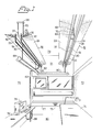
- Figure 1 illustrates an office having a face wall 71 with a windown therein, and walls 72, 73 extending at right angles from the face wall 71. Shown at 74 is a desk, while tables or benches carrying telephone 75 and data-processor 76 are referenced 77 and 78 respectively.
- Two composite sections 10 are mounted on the ceiling 79 parallel with one another and parallel with walls 72, 73, said sections having one end located at a distance from the wall 71 and suitably extending towards the viewer 'of Figure 1 and transverely through the whole building, for example transverely through a corridor located outside the illustrated office, and through a further room located on the other side of the building remote from face wall 71.
- the inlets and outlets 12, 13, 57, 58 for the attemperating medium, together with lines for supplying said attemperating medium to and passing said medium away from a plurality of composite sections 10, together with electrical supply lines, telephone lines, data-supply lines etc. extending to and from the rooms on either side of the corridor can be arranged in the corridor, adjacent the ceiling thereof, suitably hidden by a false ceiling.
- a down-lead conduit For the purpose of leading the aforementioned electrical, telephone, and data-supply lines etc., 27 - 30 downwardly from respective composite section there is arranged in the interspace 31 in the manner illustrated in Figures 1 and 2 a down-lead conduit, the lower end of which rests against the floor 80 and which is shown to include an upper part 82 and a lower part 83 which extend parallel with one another but which are offset relative to one another and joined via an obliquely positioned intermediate member 81.
- the conduit 81 - 83 is firmly held at its upper end in a selected position of rotation by means of a holder means only partially shown in the drawings.
- This holder means comprises a sleeve 84 arranged to receive the conduit Dart 82, which can be locked in a selected position by means of a screw 85. Extending from the sleeve 84 are arms 86 which are locked securely to a respective one of'the box-sections 19, 20 by means of nuts or screws 87 arranged to co-act with nuts held in the mounting grooves 43.
- the holder means 84 - 87 can be mounted at any location whatsoever along the length of the composite sections 10 and the extent to which the mutually parallel conduit parts 82, 83 are offset relative to one another is suitably selected so as to correspond to half the centre distance between the composite sections 10, thereby enabling the conduit part 83 with its outlets 88 for said electrical, telephone, data supply lines etc. to be positioned at any selected location in the room.
- FIG. 1 illustrates overhead light-fittings 89, 90 suspended from the lower mounting grooves 42 in box-sections 19, 20, while Figure 2 illustrates intermediate supply sockets 91 arranged on an L-shaped bracket structure 92, which in turn is fastened to the box-section 19 by means of screws or bolts, of which one is shown at 93 and engages a nut held in the upper mounting groove 43 of the box-section 19.
- the shelf surfaces 25, 26 can carry channel-sections along the length of the device 10 for accommodating supply lines 27 - 30. It is preferred, however, that as large an area as possible of the upper side of the inserts of sound-absorbing material 46 is left free, so that said material is able to absorb effectively sound energy reflected against the ceiling : 67.
- the sound absorbers may be arranged at any selected level in relation to the section part 19, 20 and may comprise channels containing sound absorbing material which channels have a substantially horizontal bottom and may be-laterally spaced from a respective one of the outer sides 21, 22 of said section part.
- the attempering medium or media preferably comprises liquid, such as water, and the section part 19, 20 of the composite section 10 may be provided with means (not shown) for ventilating the room equipped with'said composite section.
Landscapes
- Engineering & Computer Science (AREA)
- Architecture (AREA)
- Physics & Mathematics (AREA)
- Electromagnetism (AREA)
- Civil Engineering (AREA)
- Structural Engineering (AREA)
- Building Environments (AREA)
- Paper (AREA)
- Burglar Alarm Systems (AREA)
- Details Of Garments (AREA)
- Supports For Pipes And Cables (AREA)
- Materials For Medical Uses (AREA)
- Diaphragms For Electromechanical Transducers (AREA)
Priority Applications (1)
| Application Number | Priority Date | Filing Date | Title |
|---|---|---|---|
| AT82850198T ATE15245T1 (de) | 1981-10-16 | 1982-10-12 | Zusammengesetztes teil. |
Applications Claiming Priority (2)
| Application Number | Priority Date | Filing Date | Title |
|---|---|---|---|
| SE8106140A SE431240B (sv) | 1981-10-16 | 1981-10-16 | Profilelement |
| SE8106140 | 1981-10-16 |
Publications (2)
| Publication Number | Publication Date |
|---|---|
| EP0077763A1 true EP0077763A1 (de) | 1983-04-27 |
| EP0077763B1 EP0077763B1 (de) | 1985-08-28 |
Family
ID=20344814
Family Applications (1)
| Application Number | Title | Priority Date | Filing Date |
|---|---|---|---|
| EP82850198A Expired EP0077763B1 (de) | 1981-10-16 | 1982-10-12 | Zusammengesetztes Teil |
Country Status (5)
| Country | Link |
|---|---|
| EP (1) | EP0077763B1 (de) |
| AT (1) | ATE15245T1 (de) |
| DE (1) | DE3265870D1 (de) |
| NO (1) | NO153696C (de) |
| SE (1) | SE431240B (de) |
Citations (3)
| Publication number | Priority date | Publication date | Assignee | Title |
|---|---|---|---|---|
| US3409766A (en) * | 1967-01-04 | 1968-11-05 | Lithonia Lighting Inc | Combination lighting and cooling system |
| US3848385A (en) * | 1970-06-12 | 1974-11-19 | Nat Ceiling Corp | Modular ceiling construction |
| DE2825746A1 (de) * | 1977-06-13 | 1978-12-14 | Bror Norell | Heizelemente enthaltende baueinheit fuer decken |
-
1981
- 1981-10-16 SE SE8106140A patent/SE431240B/sv not_active IP Right Cessation
-
1982
- 1982-10-12 AT AT82850198T patent/ATE15245T1/de not_active IP Right Cessation
- 1982-10-12 DE DE8282850198T patent/DE3265870D1/de not_active Expired
- 1982-10-12 EP EP82850198A patent/EP0077763B1/de not_active Expired
- 1982-10-15 NO NO823449A patent/NO153696C/no unknown
Patent Citations (3)
| Publication number | Priority date | Publication date | Assignee | Title |
|---|---|---|---|---|
| US3409766A (en) * | 1967-01-04 | 1968-11-05 | Lithonia Lighting Inc | Combination lighting and cooling system |
| US3848385A (en) * | 1970-06-12 | 1974-11-19 | Nat Ceiling Corp | Modular ceiling construction |
| DE2825746A1 (de) * | 1977-06-13 | 1978-12-14 | Bror Norell | Heizelemente enthaltende baueinheit fuer decken |
Also Published As
| Publication number | Publication date |
|---|---|
| NO823449L (no) | 1983-04-18 |
| NO153696C (no) | 1986-05-07 |
| EP0077763B1 (de) | 1985-08-28 |
| SE8106140L (sv) | 1983-04-17 |
| ATE15245T1 (de) | 1985-09-15 |
| DE3265870D1 (en) | 1985-10-03 |
| NO153696B (no) | 1986-01-27 |
| SE431240B (sv) | 1984-01-23 |
Similar Documents
| Publication | Publication Date | Title |
|---|---|---|
| US20090152001A1 (en) | Service posts for electrical and air delivery to workstations | |
| JP3516958B2 (ja) | モジュラー式オフィスファニチュアの間仕切り | |
| US4224769A (en) | Space divider system | |
| US5516068A (en) | Device support bracket | |
| EP0863714B1 (de) | Fliesenplattesystem | |
| US20250230652A1 (en) | Building panel system | |
| JP3307631B2 (ja) | 電化壁パネルシステム | |
| JPH0526481B2 (de) | ||
| US4286419A (en) | Building structure and coupling profile associated therewith | |
| JPH0923529A (ja) | ケーブル支持用トレイ | |
| US8769884B2 (en) | Self-supporting modular panel for office furnishing | |
| CA2241289A1 (en) | Workspace wall system with elevated raceway | |
| US6293056B1 (en) | Multi-purpose above-ceiling utility support system | |
| JP5606535B2 (ja) | パーティションシステム | |
| US3730464A (en) | Sheet metal bracket | |
| US12320501B2 (en) | Frame for lighting or junction box and I-bracket | |
| EP0077763B1 (de) | Zusammengesetztes Teil | |
| CN212616737U (zh) | 一种高度可调的定型化综合防腐蚀支架 | |
| US9337636B2 (en) | Modular fastening system | |
| US5503359A (en) | Mounting box for ceiling fans | |
| US3687056A (en) | Ceiling structure ii | |
| CN1164266A (zh) | 模块化办公家具隔板 | |
| KR100390141B1 (ko) | 모듈식사무실칸막이와칸막이부재및그설치방법 | |
| GB2431570A (en) | Modular furniture system with service conduit | |
| JPH04221167A (ja) | 建築物の床下配管・配線構造 |
Legal Events
| Date | Code | Title | Description |
|---|---|---|---|
| PUAI | Public reference made under article 153(3) epc to a published international application that has entered the european phase |
Free format text: ORIGINAL CODE: 0009012 |
|
| AK | Designated contracting states |
Designated state(s): AT BE CH DE FR GB IT LI LU NL SE |
|
| 17P | Request for examination filed |
Effective date: 19831005 |
|
| GRAA | (expected) grant |
Free format text: ORIGINAL CODE: 0009210 |
|
| AK | Designated contracting states |
Designated state(s): AT BE CH DE FR GB IT LI LU NL SE |
|
| PG25 | Lapsed in a contracting state [announced via postgrant information from national office to epo] |
Ref country code: NL Effective date: 19850828 Ref country code: IT Free format text: LAPSE BECAUSE OF FAILURE TO SUBMIT A TRANSLATION OF THE DESCRIPTION OR TO PAY THE FEE WITHIN THE PRESCRIBED TIME-LIMIT;WARNING: LAPSES OF ITALIAN PATENTS WITH EFFECTIVE DATE BEFORE 2007 MAY HAVE OCCURRED AT ANY TIME BEFORE 2007. THE CORRECT EFFECTIVE DATE MAY BE DIFFERENT FROM THE ONE RECORDED. Effective date: 19850828 Ref country code: AT Effective date: 19850828 |
|
| REF | Corresponds to: |
Ref document number: 15245 Country of ref document: AT Date of ref document: 19850915 Kind code of ref document: T |
|
| PG25 | Lapsed in a contracting state [announced via postgrant information from national office to epo] |
Ref country code: SE Effective date: 19850830 |
|
| REF | Corresponds to: |
Ref document number: 3265870 Country of ref document: DE Date of ref document: 19851003 |
|
| ET | Fr: translation filed | ||
| PG25 | Lapsed in a contracting state [announced via postgrant information from national office to epo] |
Ref country code: LU Free format text: LAPSE BECAUSE OF NON-PAYMENT OF DUE FEES Effective date: 19851031 |
|
| NLV1 | Nl: lapsed or annulled due to failure to fulfill the requirements of art. 29p and 29m of the patents act | ||
| PLBE | No opposition filed within time limit |
Free format text: ORIGINAL CODE: 0009261 |
|
| STAA | Information on the status of an ep patent application or granted ep patent |
Free format text: STATUS: NO OPPOSITION FILED WITHIN TIME LIMIT |
|
| 26N | No opposition filed | ||
| PGFP | Annual fee paid to national office [announced via postgrant information from national office to epo] |
Ref country code: GB Payment date: 19931011 Year of fee payment: 12 |
|
| PGFP | Annual fee paid to national office [announced via postgrant information from national office to epo] |
Ref country code: FR Payment date: 19931013 Year of fee payment: 12 |
|
| PGFP | Annual fee paid to national office [announced via postgrant information from national office to epo] |
Ref country code: CH Payment date: 19931025 Year of fee payment: 12 |
|
| PGFP | Annual fee paid to national office [announced via postgrant information from national office to epo] |
Ref country code: BE Payment date: 19931105 Year of fee payment: 12 |
|
| PGFP | Annual fee paid to national office [announced via postgrant information from national office to epo] |
Ref country code: DE Payment date: 19931214 Year of fee payment: 12 |
|
| PG25 | Lapsed in a contracting state [announced via postgrant information from national office to epo] |
Ref country code: GB Effective date: 19941012 |
|
| PG25 | Lapsed in a contracting state [announced via postgrant information from national office to epo] |
Ref country code: LI Effective date: 19941031 Ref country code: CH Effective date: 19941031 Ref country code: BE Effective date: 19941031 |
|
| BERE | Be: lapsed |
Owner name: TENGBOMS ARKITEKTKONTOR A.B. Effective date: 19941031 |
|
| GBPC | Gb: european patent ceased through non-payment of renewal fee |
Effective date: 19941012 |
|
| PG25 | Lapsed in a contracting state [announced via postgrant information from national office to epo] |
Ref country code: FR Effective date: 19950630 |
|
| REG | Reference to a national code |
Ref country code: CH Ref legal event code: PL |
|
| PG25 | Lapsed in a contracting state [announced via postgrant information from national office to epo] |
Ref country code: DE Effective date: 19950701 |
|
| REG | Reference to a national code |
Ref country code: FR Ref legal event code: ST |