EP0078036B1 - Clavier pour appareils terminaux de communication - Google Patents
Clavier pour appareils terminaux de communication Download PDFInfo
- Publication number
- EP0078036B1 EP0078036B1 EP19820109787 EP82109787A EP0078036B1 EP 0078036 B1 EP0078036 B1 EP 0078036B1 EP 19820109787 EP19820109787 EP 19820109787 EP 82109787 A EP82109787 A EP 82109787A EP 0078036 B1 EP0078036 B1 EP 0078036B1
- Authority
- EP
- European Patent Office
- Prior art keywords
- keyboard
- procedure
- dialling
- circuit boards
- electronic assembly
- Prior art date
- Legal status (The legal status is an assumption and is not a legal conclusion. Google has not performed a legal analysis and makes no representation as to the accuracy of the status listed.)
- Expired
Links
- 238000004891 communication Methods 0.000 title claims description 3
- 238000000034 method Methods 0.000 claims description 14
- 238000005516 engineering process Methods 0.000 claims description 4
- 125000006850 spacer group Chemical group 0.000 claims description 4
- 230000000712 assembly Effects 0.000 claims description 3
- 238000000429 assembly Methods 0.000 claims description 3
- 238000011161 development Methods 0.000 description 3
- 238000013461 design Methods 0.000 description 2
- 239000004020 conductor Substances 0.000 description 1
- 239000013013 elastic material Substances 0.000 description 1
- 239000004973 liquid crystal related substance Substances 0.000 description 1
- 238000004519 manufacturing process Methods 0.000 description 1
- 210000000056 organ Anatomy 0.000 description 1
- 238000003825 pressing Methods 0.000 description 1
- 238000005476 soldering Methods 0.000 description 1
- 238000012360 testing method Methods 0.000 description 1
- 238000012549 training Methods 0.000 description 1
Images
Classifications
-
- H—ELECTRICITY
- H04—ELECTRIC COMMUNICATION TECHNIQUE
- H04M—TELEPHONIC COMMUNICATION
- H04M1/00—Substation equipment, e.g. for use by subscribers
- H04M1/02—Constructional features of telephone sets
- H04M1/23—Construction or mounting of dials or of equivalent devices; Means for facilitating the use thereof
Definitions
- the invention relates to a keyboard for terminals in communication technology with a dialing and procedure keyboard as well as a display device, the keyboard consisting of individual, independent assemblies which are assembled in such a way that the procedure keyboard is arranged to the side of the dialing keyboard and furthermore below the dialing and Procedure keyboard which is arranged with components of printed circuit boards of an electronic assembly.
- keyboards have been developed in particular in the field of telephone technology, on which, in addition to the usual keyboard, additional program keys are arranged which enable automatic callback, redialing, call diversion, speed dialing, among others.
- Such keyboards are combined into a module and can be used in a telephone.
- it is known to display certain numbers, charges or the like on a display for comfort or special telephones. The display is then arranged as a single assembly at a clearly visible location on the telephone set.
- a dialing keypad can be exchanged for a number switch.
- the keypad consists of individual, independent assemblies which are assembled in such a way that the procedure keypad is arranged to the side of the dialing keypad and still below the dialing and procedure keyboard which is arranged from printed circuit boards of electronic components equipped with components.
- a telephone set is also known, the components of which are partly arranged in trough-like recesses in the housing.
- This device can also be equipped with a more or less large number of additional devices, depending on requirements.
- the object of the invention is to design a keyboard for telephone sets in such a way that the largest possible number of additional devices can be accommodated in the smallest of spaces, so that the smaller telephone set also has greater ease of use.
- one of the printed circuit boards prefferably be of elongated design and to carry a fee lock and a 16 kHz module in its elongated part.
- a further advantageous development provides that the connectors of the plug connector penetrate the female connector during assembly and end in the female connector of the printed circuit board.
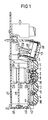
- the keyboard module consists of a trough-shaped, rectangular plastic housing 5, which has square recesses for the keys on the side facing the keys 1, 2, 3.
- the buttons are inserted from the inside into the plastic housing and secured against falling out by lugs.
- the buttons are followed by a contact mat 6 made of elastic material, which has bellows 7, 8, 9, 10 facing the buttons. Inside, the bellows carry contact pieces, of which the contact piece 11 of the bellows 8 can be seen.
- the contact mat 6 is followed by a circuit board 12, which carries a network of conductor tracks, some of which can be bridged by the contact pieces of the lifting bellows.
- the circuit board 12 is located on one side behind a recess 13 of the housing and is additionally fastened with a screw or the like in the trough-shaped plastic housing.
- the device described so far forms a self-contained unit that can be subjected to an individual test in terms of production technology.
- Another unit is the electronic assembly, which consists of two circuit boards 14, 15 equipped with electrical components and which are separated from one another by a spacer frame 16.
- a further unit is formed by the display device 17, which consists of a liquid crystal display and a control device.
- This display device is arranged in a recess in the trough-shaped plastic housing 5 and is inclined with respect to the operating level.
- the display device is covered by a frame-like, sandblasted, matted cover plate 18, which is connected to the trough-shaped plastic housing 5 by a snap-in connection.
- the display device 17 and the circuit board 12 are provided with connectors 19, 20, the connectors of the connector 19 ending in the female connector 21 during assembly.
- the plugs of the connector 20 penetrate the female connector 22 upon contact and end in a further female connector 23 of the circuit board 14. All the electrical connections are thus made automatically when the various units are assembled.
- the spacer frame 16 has a plurality of peg-like elevations 24 which, when the units are assembled, lie behind the circuit board 12 and form an abutment.
- a last unit consists of a charge lock 25 and a 16 kHz receive module, which are arranged on an extended part of the circuit board 14 and are electrically contacted.
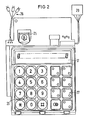
- the top view of the keyboard module shown in FIG. 2 shows the dialing organs 26, which are formed by the known keys and the procedure keys 27 are arranged next to them.
- the two groups are optically separated from one another by the increased distance between these keys.
- the display device 17 is arranged above these keys and is inclined at approximately 15 ° with respect to the operating plane formed by the keys, so that the visibility is increased.
- the fee lock 25 and further plugs 28 and 29 can also be seen.
Landscapes
- Engineering & Computer Science (AREA)
- Signal Processing (AREA)
- Input From Keyboards Or The Like (AREA)
- Telephone Set Structure (AREA)
Claims (4)
Applications Claiming Priority (2)
| Application Number | Priority Date | Filing Date | Title |
|---|---|---|---|
| DE19813142414 DE3142414A1 (de) | 1981-10-26 | 1981-10-26 | Tastatur fuer kommunkationsendgeraete |
| DE3142414 | 1981-10-26 |
Publications (3)
| Publication Number | Publication Date |
|---|---|
| EP0078036A2 EP0078036A2 (fr) | 1983-05-04 |
| EP0078036A3 EP0078036A3 (en) | 1985-01-23 |
| EP0078036B1 true EP0078036B1 (fr) | 1988-06-01 |
Family
ID=6144846
Family Applications (1)
| Application Number | Title | Priority Date | Filing Date |
|---|---|---|---|
| EP19820109787 Expired EP0078036B1 (fr) | 1981-10-26 | 1982-10-22 | Clavier pour appareils terminaux de communication |
Country Status (3)
| Country | Link |
|---|---|
| EP (1) | EP0078036B1 (fr) |
| JP (1) | JPS5881365A (fr) |
| DE (1) | DE3142414A1 (fr) |
Families Citing this family (7)
| Publication number | Priority date | Publication date | Assignee | Title |
|---|---|---|---|---|
| JPS5952164U (ja) * | 1982-09-30 | 1984-04-05 | 日野自動車株式会社 | 空気吸込口構造 |
| GB2154393A (en) * | 1984-02-16 | 1985-09-04 | Standard Telephones Cables Ltd | Telephone subscriber's apparatus |
| GB8524843D0 (en) * | 1985-10-09 | 1985-11-13 | Philips Electronic Associated | Telephone instrument |
| DE3704738A1 (de) * | 1986-03-08 | 1988-08-25 | Telefonbau & Normalzeit Gmbh | Endgeraet mit einem, eine tastatur tragenden schlitten, welcher eine weitere tastatur oder anzeigevorrichtung freigibt |
| JPH084764Y2 (ja) * | 1989-05-26 | 1996-02-07 | 岩崎通信機株式会社 | ボタン電話機 |
| JPH084763Y2 (ja) * | 1989-05-26 | 1996-02-07 | 岩崎通信機株式会社 | ボタン電話機 |
| DE3941712A1 (de) * | 1989-12-18 | 1991-06-27 | Standard Elektrik Lorenz Ag | Drucktastenanordnung |
Family Cites Families (3)
| Publication number | Priority date | Publication date | Assignee | Title |
|---|---|---|---|---|
| DE2355666A1 (de) * | 1973-11-07 | 1975-05-22 | Standard Elektrik Lorenz Ag | Fernsprechapparat |
| DE7540564U (de) * | 1975-12-19 | 1976-10-21 | S. Siedle & Soehne, Telefon- U. Telegrafenwerke Gmbh, 7743 Furtwangen | Schaltgeraet fuer gegen- oder wechselsprechverkehr |
| DE2902052A1 (de) * | 1979-01-19 | 1980-07-24 | Siemens Ag | Elektrisches geraet, insbesondere fernsprechgeraet, mit einem einen hohlraum umschliessenden gehaeuse |
-
1981
- 1981-10-26 DE DE19813142414 patent/DE3142414A1/de not_active Withdrawn
-
1982
- 1982-10-22 EP EP19820109787 patent/EP0078036B1/fr not_active Expired
- 1982-10-25 JP JP57186239A patent/JPS5881365A/ja active Pending
Also Published As
| Publication number | Publication date |
|---|---|
| JPS5881365A (ja) | 1983-05-16 |
| EP0078036A3 (en) | 1985-01-23 |
| EP0078036A2 (fr) | 1983-05-04 |
| DE3142414A1 (de) | 1983-05-05 |
Similar Documents
| Publication | Publication Date | Title |
|---|---|---|
| DE3688351T2 (de) | Fernsprecher. | |
| DE29713756U1 (de) | Wasserdichte Tastatureinrichtung | |
| DE2706681A1 (de) | Schutzeinrichtung fuer niederspannungsleitungen, insbesondere fuer fernsprechnetze | |
| EP0092084B1 (fr) | Installation téléphonique à émetteur de messages intégré électronique | |
| EP0064615B1 (fr) | Equipement téléphonique avec clavier sélecteur | |
| DE1223889B (de) | Fernsprechteilnehmergeraet | |
| EP0078036A2 (fr) | Clavier pour appareils terminaux de communication | |
| EP0890205B1 (fr) | Dispositif de distribution d'un distributeur dans un systeme de telecommunications | |
| DD297285A5 (de) | Verteilerleiste fuer eine telekommunikationsanlage | |
| DE2649566A1 (de) | Rechner mit leuchtstoffroehren-anzeige | |
| DE3736025C1 (en) | Multiple plug connector | |
| DE3002563A1 (de) | Mehrfach-anschlussdose | |
| EP0740498A2 (fr) | Connecteur électrique | |
| DE2232322A1 (de) | Programmierbare schaltungsvorrichtung fuer flachdraht-flachkabelverbindungen | |
| EP0024724B1 (fr) | Commutateur à bouton-poussoir pour la télécommunication | |
| EP0007088B1 (fr) | Dispositif pour actionner des contacts | |
| DE2643088A1 (de) | Verteileranordnung fuer fernmeldevermittlungsanlagen | |
| DE2046729A1 (de) | Prüfklemme für lötfreie Verbindungen mit integrierten Bausteinen | |
| DE3435773A1 (de) | Rueckwandverdrahtung fuer einschiebbare elektrische baugruppen | |
| DE8507560U1 (de) | Elektrisches Tastenfeld | |
| AT385616B (de) | Tastwahlblock, z.b. fuer fernsprechapparate, vermittlungstische, datenterminals od.dgl. | |
| DE2530151B2 (de) | Vorrichtung zur gleichzeitigen elektrischen und mechanischen Verbindung von Nachrichtengeräten, insbesondere Fernsprechgeräten | |
| DE3704738A1 (de) | Endgeraet mit einem, eine tastatur tragenden schlitten, welcher eine weitere tastatur oder anzeigevorrichtung freigibt | |
| DE2903000A1 (de) | Schaltkabel mit an den kabelenden montierten steckern | |
| DE4115001C2 (de) | Verfahren zum unterbrechungsfreien Umschalten bestehender Anschlüsse isolierter Verbindungsdrähte insbesondere in einem Telefonnetz und Steckvorrichtung für ein derartiges Verfahren |
Legal Events
| Date | Code | Title | Description |
|---|---|---|---|
| PUAI | Public reference made under article 153(3) epc to a published international application that has entered the european phase |
Free format text: ORIGINAL CODE: 0009012 |
|
| AK | Designated contracting states |
Designated state(s): FR GB NL SE |
|
| PUAL | Search report despatched |
Free format text: ORIGINAL CODE: 0009013 |
|
| AK | Designated contracting states |
Designated state(s): FR GB NL SE |
|
| 17P | Request for examination filed |
Effective date: 19850722 |
|
| 17Q | First examination report despatched |
Effective date: 19860424 |
|
| GRAA | (expected) grant |
Free format text: ORIGINAL CODE: 0009210 |
|
| AK | Designated contracting states |
Kind code of ref document: B1 Designated state(s): FR GB NL SE |
|
| ET | Fr: translation filed | ||
| GBT | Gb: translation of ep patent filed (gb section 77(6)(a)/1977) | ||
| PLBE | No opposition filed within time limit |
Free format text: ORIGINAL CODE: 0009261 |
|
| STAA | Information on the status of an ep patent application or granted ep patent |
Free format text: STATUS: NO OPPOSITION FILED WITHIN TIME LIMIT |
|
| 26N | No opposition filed | ||
| PG25 | Lapsed in a contracting state [announced via postgrant information from national office to epo] |
Ref country code: GB Effective date: 19891022 |
|
| PG25 | Lapsed in a contracting state [announced via postgrant information from national office to epo] |
Ref country code: SE Effective date: 19891023 |
|
| PG25 | Lapsed in a contracting state [announced via postgrant information from national office to epo] |
Ref country code: NL Effective date: 19900501 |
|
| NLV4 | Nl: lapsed or anulled due to non-payment of the annual fee | ||
| GBPC | Gb: european patent ceased through non-payment of renewal fee | ||
| PG25 | Lapsed in a contracting state [announced via postgrant information from national office to epo] |
Ref country code: FR Effective date: 19900629 |
|
| REG | Reference to a national code |
Ref country code: FR Ref legal event code: ST |
|
| EUG | Se: european patent has lapsed |
Ref document number: 82109787.0 Effective date: 19900705 |