EP0078059A2 - Verfahren zum Aufnehmen von Audio/Videosignalen - Google Patents
Verfahren zum Aufnehmen von Audio/Videosignalen Download PDFInfo
- Publication number
- EP0078059A2 EP0078059A2 EP82109935A EP82109935A EP0078059A2 EP 0078059 A2 EP0078059 A2 EP 0078059A2 EP 82109935 A EP82109935 A EP 82109935A EP 82109935 A EP82109935 A EP 82109935A EP 0078059 A2 EP0078059 A2 EP 0078059A2
- Authority
- EP
- European Patent Office
- Prior art keywords
- frequency
- signal
- audio
- modulated
- video
- Prior art date
- Legal status (The legal status is an assumption and is not a legal conclusion. Google has not performed a legal analysis and makes no representation as to the accuracy of the status listed.)
- Ceased
Links
Images

Classifications
-
- G—PHYSICS
- G11—INFORMATION STORAGE
- G11B—INFORMATION STORAGE BASED ON RELATIVE MOVEMENT BETWEEN RECORD CARRIER AND TRANSDUCER
- G11B5/00—Recording by magnetisation or demagnetisation of a record carrier; Reproducing by magnetic means; Record carriers therefor
- G11B5/02—Recording, reproducing, or erasing methods; Read, write or erase circuits therefor
- G11B5/027—Analogue recording
-
- H—ELECTRICITY
- H04—ELECTRIC COMMUNICATION TECHNIQUE
- H04N—PICTORIAL COMMUNICATION, e.g. TELEVISION
- H04N9/00—Details of colour television systems
- H04N9/79—Processing of colour television signals in connection with recording
- H04N9/80—Transformation of the television signal for recording, e.g. modulation, frequency changing; Inverse transformation for playback
- H04N9/82—Transformation of the television signal for recording, e.g. modulation, frequency changing; Inverse transformation for playback the individual colour picture signal components being recorded simultaneously only
- H04N9/8205—Transformation of the television signal for recording, e.g. modulation, frequency changing; Inverse transformation for playback the individual colour picture signal components being recorded simultaneously only involving the multiplexing of an additional signal and the colour video signal
- H04N9/8211—Transformation of the television signal for recording, e.g. modulation, frequency changing; Inverse transformation for playback the individual colour picture signal components being recorded simultaneously only involving the multiplexing of an additional signal and the colour video signal the additional signal being a sound signal
- H04N9/8222—Transformation of the television signal for recording, e.g. modulation, frequency changing; Inverse transformation for playback the individual colour picture signal components being recorded simultaneously only involving the multiplexing of an additional signal and the colour video signal the additional signal being a sound signal using frequency division multiplex
Definitions
- the present invention relates to a method for modulating carrier frequencies with video and audio information and for selecting the carrier frequencies such that the resultant frequency components are arranged throughout the frequency spectrum so as to optimize the information storage capability of the recording medium.
- the present invention is adapted particularly for use in connection with a recording medium in which recorded signal amplitude variations are not used to carry information.
- a recording medium is the optical disc.
- An optical disc is a clear plastic disc approximately the size of an LP phonograph record, which has an information carrying surface embedded in its interior. A uniformly reflective surface may be provided and small indicia, such as small pits, having altered reflective properties may be arranged sequentially in circular or spiralling tracks.
- the disc is read by imaging a beam of light onto a track and causing the disc to rotate so that the spot of light scans along the track.
- the light which is reflected off of the surface is detected by a photodetector which produces an electrical signal in response to the light. Variations in the intensity of the reflected light due to the alternate presence or absence of the indicia cause variations in the electrical signal. These variations in the electrical signal represent the information stored in the disc.
- Information is stored in the disc in the form of variations in the spatial frequency of the indicia in the track, and also in "duty cycle” variations, that is, variations in the relative length of the indicia as compared with the "land” of reflective surface between them.
- the spatial frequency and duty cycle variations of the indicia cause time frequency variations and time duty cycle variations of the detected electrical signal.
- Another technique involves frequency modulating a carrier signal with a standard NTSC color video signal, and then modulating the zero crossings of the resultant FM signal with a frequency modulated audio subcarrier.
- a successful format for optical discs involves the provision of a carrier signal at a frequency of approximately 8 MHz, frequency modulated with composite video signals such that the carrier frequency corresponds to approximately 7.6 MHz, and full white corresponds to approximately 9.3 MHz.
- Two separate frequency modulated audio subcarriers are positioned in the spectrum at approximately 2.3 MHz and 2.8 MHz.
- this format has been considered to be the optimum arrangement for recording audio and video information on commercial optical video discs.
- the format yields high quality optical video disc recordings, it has been known that when using this format the recording and playback parameters of both the electrical and mechanical systems must be maintained within very close tolerances to avoid the introduction of excessively large second order harmonic intermodulation products, especially resulting from the presence of the audio subcarriers.
- the present invention fulfills these needs.
- the method comprises modulating a carrier signal with a color video signal, modulating a subcarrier frequency with an audio frequency signal, selecting the carrier and subcarrier frequencies such that the upper frequency deviation limit of the frequency modulated carrier signal is lower than the useful frequency upper limit of the recording medium, and selecting the subcarrier frequency to be less than the lower second chrominance sideband of the modulated carrier.
- the frequency modulated subcarrier and carrier signals are added, and the zero crossings of the resultant signal are detected. The detected zero crossings are then recorded on the recording medium.
- carrier frequency and deviation ratio are selected such that the necessary information for high quality video recording and playback lie within the confines of the useful frequency limit of the optical disc, while at the same time a region in the spectrum below the lower second order color frequency sideband is created having sufficient frequency bandwi.ith so as to enable the insertion of a frequency modulated audio subcarrier in the region of approximately 0.5 to 1.0 MHz.
- Figure 1 shows several waveforms which illustrate the modulation technique used in connection with the preferred embodiment of the present invention.
- Figure 1 A shows an approximately sinusoidal waveform 10 of a subcarrier signal frequency modulated with audio frequency information.
- Figure 1B shows a carrier signal frequency waveform 12 modulated with color video information.
- Figure 1C shows a composite signal 14 resulting from the addition of the signals shown in Figures lA and 1B.
- the waveform 10' of the subcarrier signal is shown in dashed lines as an envelope of the composite signal to better illustrate the result of the addition of the two signals.
- Figure 1D shows a square wave constructed from the zero crossing information of the composite signal 14.
- the square wave signal 48 contains the same information as the composite signal 14 in frequency and zero crossing variations and can be used to record the information on a medium in which amplitude variations do not play a role.
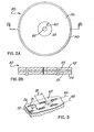
- Figure 2A is a plan view depicting an optical disc 50 used in connection with the practice of the preferred embodiment of the present invention.
- Figure 2B is a cross section view of optical disc 50 through line B-B of Figure 2 .
- the disc 50 is made of two pieces 52, 54, of optically clear plastic which are bonded together, for example with adhesive glue.
- the interior, facing surfaces 53, 55 of the two pieces 52, 54, respectively, are reflective and comprise the information carrying surfaces of the disc between concentric circles 58 and 60, as shown. These surfaces are typically provided with a coating of metal to enhance their reflectance. Having two reflective, information carrying surfaces, the disc is "two sided".
- Figure 3 depicts a section of one of the pieces 52 of the disc 50, greatly magnified, showing two adjacent tracks 66, 68, of information indicia 70.
- the indicia 70 are formed as elongated pits in the reflective surface 56, spaced sequentially in the form of a continuous (preferably spiral) track.
- the coating of metal 65 follows the contour of the reflective surface 56.
- the length of the pits 70 as depicted by arrow 72, varies in accordance with the information content, but is of the order of magnitude of approximately one micron.
- the spacing between pits in a track also varies in accordance with the information content and is approximately one micron. Track to track spacing, or pitch, as depicted by arrow 74, is nominally 1.67 microns.
- the indicia such as the pits 70 shown on Figure 3, can be formed in the reflective surface 56 in accordance with any one of a number of known processes. In all such cases information is recorded by varying the length and frequency of occurrence of the indicia in accordance with an information signal such as square wave 48 ( Figure 1) discussed above.
- an information signal such as square wave 48 ( Figure 1) discussed above.
- the positive-going half cycles of square wave 48 may correspond to the indicia and the negative-going half cycles to the "lands" of reflective surface there between, or vice versa.
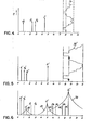
- Figure 4 is a graph showing a prior art frequency format for-an optical disc having an upper frequency limit of about 13 MHz.
- the horizontal axis corresponds to frequency, while the vertical axis correcponds to time.
- the carrier frequency at 8.0 MHz is frequency modulated with a video signal such that synch tips corresponds to 7.6 MHz, blanking corresponds to the carrier (8.0 MHz) and full white corresponds to 9.3 MHz, as depicted by time-line 76.
- the audio subcarriers, A 1 and A 2 are shown on the graph as vectors. It will be understood that the audip subcarriers have bandwidths approximately 100 KHz wide.
- the two lower chroma sidebands, J 1 and J 2 are also shown, as vectors, to show-their relation to the audio subcarriers A 1 and A 2 .
- the video carrier frequency was selected such that the first order chroma side band appears "to the right" of (higher in frequency than) the intermodulation component equal in frequency to the difference between the video carrier frequency and the frequency of the lower first order chroma side band, while the upper first order chroma side band is maintained within the useful frequency bandwidth of the disc.
- the audio carriers A l and A 2 were located in the "hole” in the spectrum between the side band components 11and J 2 . It was considered that this frequency selection yields minimum unwanted visible disturbance of the video picture as a result of the appearance in the spectrum of unwanted intermodulation products.
- FIG. 5 shows a frequency spectrum illustrating a format for recording video and audio information onto a recording medium according to the preferred embodiment of the present invention.
- a color video signal including luminance and chrominance signal information, frequency modulates a carrier signal having a frequency of 8.6 M Hz. Frequency deviation limits are illustrated by the time line 76' shown on the graph. Thus, sync tip corresponds to 7.6 MHz, blanking corresponds to 8.6 MHz, while full white corresponds to 11 MHz.
- Audio subcarriers A 1 ' and A 2 ' are provided at 0.5 and 1.0 MHz, respectively.
- the first and second lower chroma sidebands J1 and J 2 1 are shown to illustrate their relation to the audio subcarriers A 1 ' and A 2 '. As can be seen, the audio subcarriers A 1 ' and A 2 ' appear to the left of the second lower chroma sideband, that is, they are lower in frequency than the J 2 ' sideband.
- Figure 6 is a frequency spectrum showing the major frequency components resulting from the frequency modulation format depicted in Figure 5. Whereas in Figure 5 the vertical axis represents time for the purposes of illustration, in Figure 6 the vertical axis represents amplitude. Thus it will be appreciated that the graph of Figure 6 represents the actual frequency components which are generated as a result of providing modulated signals in accordance with the format depicted in Figure 5.
- Shown in Figure 6 are the video carrier itself, J 0 ', the first and second lower chroma sidebands, J 1 ' and J 2 ', respectively, and the two audio subcarriers A 1 ' and A 2 '. Also shown are the most significant second order intermodulation products IM 1 ' and IM 2 ' resulting from the intermodulation between the audio subcarriers A 1 ' and A 2 ' and the video carrier J 0 '. These intermodulation products IM 1 ' and iM 2 ' appear at frequencies equal to the difference between the audio subcarrier frequencies and the video carrier frequency.
- the intermodulation products IM 1 ' and IM 2 1 appear at frequencies equal to f c - F A1 and f c - f A2 , respectively.
- dashed lines are shown at 2.3 MHz and 2.8 MHz., representing the frequency location of audio subcarriers A 1 and A 2 , respectively, selected according to prior art principles.
- the intermodulation products IM 1 and IM 2 resulting from audio subcarriers A 1 and A 2 are also shown in dashed lines.
- envelopes 78, 80 and 82 are shown associated with frequency components J O ', J 1 ' and J 2 ', respectively. These envelopes depict the full modulation side bands which appear around each of these frequency components at frequency intervals equal to the horizontal sync frequency.
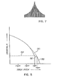
- Figure 7 illustrates the appearance of these subcarriers in more detail. From Figure 7, it will be appreciated that the envelopes 78, 80 and 82 in Figure 6 follow the configuration defined by the peak amplitudes of the numerous side band components appearing around frequency components J O ', J 1 ' and J 2 '.
- intermodulation products IM 2 and IM 2 ' can be compared.
- the signal level of component IM 2 exceeds the side band envelope level at that frequency by an amount 84, while the level of the intermodulation component IM 2 ' is less than the side band envelope level by an amount 86.
- the significance of this lies in the fact that the envelope of side band frequency components can be regarded as a kind of graph of the relative magnitude of visual effect produced in a recovered video signal for a side band frequency component at a particular frequency.
- Figure 8 is a graph showing the relationship between track pitch and crosstalk for an optical disc.
- the "S" shaped curve 88 is a plot of measured values of crosstalk versus track pitch.
- the dashed curve 90 depicts a continuation of curve 88 which might be expected, representing a relationship whereby a diminution in track pitch causes a steadily increasing crosstalk.
- the actual curve representing the relationship between crosstalk and track pitch exhibits a plateau-like region 92 such that the observed crosstalk at a track pitch of 1.5 micrometers is close in value to the amount of crosstalk measured at a track pitch of 1.65 micrometers, as shown by reference to dashed line 94.
- the plateau-like region 92 is exagerated in extent in the view for purposes of illustration. The actual effect is a somewhat more gradual curve in the region 92. This discovered relationship permits the construction of a standard sized optical video disc having an inner, limiting track radius of 65 millimeters, as contrasted with the prior art 55 millimeters.
- An inner track radius of 65 millimeters, together with a track pitch of 1.50 micrometers permits the placement of 30 minutes of program material on a single side of a disc, other parameters remaining constant.
- the number of indicia that can be "packed" into the track is increased so as to extend the bandwidth of the disc from approximately 13 MHz to approximately 15.5 MHz.
- the increase in the upper useful frequency limit of the disc permits the further advantage of increasing the deviation of the FM carrier J 0 ' from 1.8 MHz to 3.4 MHz. This has a further beneficial effect of reducing the relative effect of unwanted frequency components such as intermodulation products, and provides an approximately 6 db increase in the demodulated video signal S/N ratio as compared with the prior art format shown in Figure 4.
Landscapes
- Engineering & Computer Science (AREA)
- Multimedia (AREA)
- Signal Processing (AREA)
- Optical Recording Or Reproduction (AREA)
- Signal Processing Not Specific To The Method Of Recording And Reproducing (AREA)
- Signal Processing For Digital Recording And Reproducing (AREA)
Applications Claiming Priority (2)
| Application Number | Priority Date | Filing Date | Title |
|---|---|---|---|
| US06/316,015 US4480270A (en) | 1981-10-28 | 1981-10-28 | Audio/video signal recording method |
| US316015 | 1994-09-30 |
Publications (2)
| Publication Number | Publication Date |
|---|---|
| EP0078059A2 true EP0078059A2 (de) | 1983-05-04 |
| EP0078059A3 EP0078059A3 (de) | 1986-03-19 |
Family
ID=23227096
Family Applications (1)
| Application Number | Title | Priority Date | Filing Date |
|---|---|---|---|
| EP82109935A Ceased EP0078059A3 (de) | 1981-10-28 | 1982-10-27 | Verfahren zum Aufnehmen von Audio/Videosignalen |
Country Status (4)
| Country | Link |
|---|---|
| US (1) | US4480270A (de) |
| EP (1) | EP0078059A3 (de) |
| JP (1) | JPS5887994A (de) |
| KR (1) | KR880000863B1 (de) |
Families Citing this family (3)
| Publication number | Priority date | Publication date | Assignee | Title |
|---|---|---|---|---|
| US4683502A (en) * | 1982-08-30 | 1987-07-28 | Pioneer Electronic Corporation | Video disc type recording and reproducing system with interference reduction filter |
| NL8300541A (nl) * | 1983-02-14 | 1984-09-03 | Philips Nv | Werkwijze voor het koderen van een registratiesignaal, registratiedrager voorzien van een registratiesignaal dat gekodeerd is volgens de werkwijze, inrichting voor het uitvoeren van de werkwijze en inrichting voor het weergeven van een signaal dat gekodeerd is volgens de werkwijze. |
| US5227891A (en) * | 1988-10-12 | 1993-07-13 | Sanyo Electric Co., Ltd. | Method of recording fine color video signal on optical recording media and method of reproducing thus recorded fine color video signal |
Family Cites Families (5)
| Publication number | Priority date | Publication date | Assignee | Title |
|---|---|---|---|---|
| NL177168C (nl) * | 1972-09-02 | 1985-08-01 | Philips Nv | Werkwijze voor het registreren van een videosignaal en registratiedrager voorzien van videoinformatie opgetekend volgens de werkwijze alsmede een inrichting voor het uitlezen van een registratiedrager. |
| US3972064A (en) * | 1973-03-20 | 1976-07-27 | Rca Corporation | Apparatus and methods for playback of color picture/sound records |
| DE2418175C2 (de) * | 1974-04-13 | 1983-01-05 | Robert Bosch Gmbh, 7000 Stuttgart | Schaltungsanordnung zur Modulation eines Energiestrahls |
| US3969756A (en) * | 1974-11-12 | 1976-07-13 | Rca Corporation | Color-picture/multichannel-sound record and recording/playback apparatus and methods therefor |
| JPS5823998B2 (ja) * | 1977-03-08 | 1983-05-18 | 日本ビクター株式会社 | 情報信号記録方法 |
-
1981
- 1981-10-28 US US06/316,015 patent/US4480270A/en not_active Expired - Fee Related
-
1982
- 1982-10-27 KR KR8204826A patent/KR880000863B1/ko not_active Expired
- 1982-10-27 EP EP82109935A patent/EP0078059A3/de not_active Ceased
- 1982-10-28 JP JP57188325A patent/JPS5887994A/ja active Pending
Also Published As
| Publication number | Publication date |
|---|---|
| KR840002131A (ko) | 1984-06-11 |
| EP0078059A3 (de) | 1986-03-19 |
| JPS5887994A (ja) | 1983-05-25 |
| US4480270A (en) | 1984-10-30 |
| KR880000863B1 (ko) | 1988-05-26 |
Similar Documents
| Publication | Publication Date | Title |
|---|---|---|
| US4480270A (en) | Audio/video signal recording method | |
| US4499502A (en) | Compressed bandwidth frequency modulation signal format apparatus and method | |
| US3968513A (en) | System for recording a color television signal with reduced bandwidth | |
| EP0107295B1 (de) | Videoplatten-Aufzeichnungs- und Wiedergabesystem | |
| EP0087154A3 (de) | Verfahren und Gerät zur universellen Aufnahme und Wiedergabe von Digital kodierten Videodaten | |
| KR860001987B1 (ko) | 주파수 변조파 신호의 2차 왜곡 저감장치 | |
| US4683502A (en) | Video disc type recording and reproducing system with interference reduction filter | |
| US5084767A (en) | Television signal recording and reproducing system using optical recording medium | |
| US4486793A (en) | Reduction of crosstalk effects in modulated audio signals carried in adjacent tracks of recorded media | |
| KR0141595B1 (ko) | 고세도 컬러 영상 신호를 광학적 기록 매체에 기록하는 방법 및 이 방법으로 기록된 고세도 컬러 영상 신호를 재생하는 방법 | |
| US4477837A (en) | Video signal recording-reproducing apparatus | |
| Morita et al. | High density video disc for HDTV baseband signal | |
| Bögels | System Coding Parameters, Mechanics and Electromechanics of the Reflective Videodisc Player | |
| JPS6098789A (ja) | クロスト−ク検出装置 | |
| JPH0115943B2 (de) | ||
| JPH0229278B2 (de) | ||
| JPS62122384A (ja) | 磁気記録再生方式 | |
| JPS63312786A (ja) | 円盤状記録媒体の記録方式 | |
| JPS61248687A (ja) | ビデオデイスク装置 | |
| JPH04348686A (ja) | 光学式ビデオディスクの映像信号記録方式 | |
| JPH026146B2 (de) | ||
| JPH076402A (ja) | 光ディスク装置 | |
| JPH02192290A (ja) | 高細度ビデオディスクレコード及び高細度ビデオディスクプレーヤ | |
| JPH0279254A (ja) | ビデオ信号及びディジタル信号記録方式 | |
| JPH0549000B2 (de) |
Legal Events
| Date | Code | Title | Description |
|---|---|---|---|
| PUAI | Public reference made under article 153(3) epc to a published international application that has entered the european phase |
Free format text: ORIGINAL CODE: 0009012 |
|
| AK | Designated contracting states |
Designated state(s): AT BE CH DE FR GB IT LI LU NL SE |
|
| 17P | Request for examination filed |
Effective date: 19831223 |
|
| PUAL | Search report despatched |
Free format text: ORIGINAL CODE: 0009013 |
|
| AK | Designated contracting states |
Kind code of ref document: A3 Designated state(s): AT BE CH DE FR GB IT LI LU NL SE |
|
| 17Q | First examination report despatched |
Effective date: 19880219 |
|
| STAA | Information on the status of an ep patent application or granted ep patent |
Free format text: STATUS: THE APPLICATION HAS BEEN REFUSED |
|
| 18R | Application refused |
Effective date: 19881017 |
|
| RIN1 | Information on inventor provided before grant (corrected) |
Inventor name: WILKINSON, RICHARD L. |