EP0079965A1 - Numerisch gesteuerte vorrichtung zum bearbeiten von zahnrädern - Google Patents
Numerisch gesteuerte vorrichtung zum bearbeiten von zahnrädern Download PDFInfo
- Publication number
- EP0079965A1 EP0079965A1 EP82901613A EP82901613A EP0079965A1 EP 0079965 A1 EP0079965 A1 EP 0079965A1 EP 82901613 A EP82901613 A EP 82901613A EP 82901613 A EP82901613 A EP 82901613A EP 0079965 A1 EP0079965 A1 EP 0079965A1
- Authority
- EP
- European Patent Office
- Prior art keywords
- gear
- shaft
- rotation
- distributor
- pulse distributor
- Prior art date
- Legal status (The legal status is an assumption and is not a legal conclusion. Google has not performed a legal analysis and makes no representation as to the accuracy of the status listed.)
- Granted
Links
Images

Classifications
-
- B—PERFORMING OPERATIONS; TRANSPORTING
- B23—MACHINE TOOLS; METAL-WORKING NOT OTHERWISE PROVIDED FOR
- B23F—MAKING GEARS OR TOOTHED RACKS
- B23F23/00—Accessories or equipment combined with or arranged in, or specially designed to form part of, gear-cutting machines
- B23F23/08—Index mechanisms
-
- B—PERFORMING OPERATIONS; TRANSPORTING
- B23—MACHINE TOOLS; METAL-WORKING NOT OTHERWISE PROVIDED FOR
- B23F—MAKING GEARS OR TOOTHED RACKS
- B23F23/00—Accessories or equipment combined with or arranged in, or specially designed to form part of, gear-cutting machines
- B23F23/006—Equipment for synchronising movement of cutting tool and workpiece, the cutting tool and workpiece not being mechanically coupled
-
- G—PHYSICS
- G05—CONTROLLING; REGULATING
- G05B—CONTROL OR REGULATING SYSTEMS IN GENERAL; FUNCTIONAL ELEMENTS OF SUCH SYSTEMS; MONITORING OR TESTING ARRANGEMENTS FOR SUCH SYSTEMS OR ELEMENTS
- G05B19/00—Program-control systems
- G05B19/02—Program-control systems electric
- G05B19/18—Numerical control [NC], i.e. automatically operating machines, in particular machine tools, e.g. in a manufacturing environment, so as to execute positioning, movement or co-ordinated operations by means of program data in numerical form
- G05B19/182—Numerical control [NC], i.e. automatically operating machines, in particular machine tools, e.g. in a manufacturing environment, so as to execute positioning, movement or co-ordinated operations by means of program data in numerical form characterised by the machine tool function, e.g. thread cutting, cam making, tool direction control
- G05B19/186—Generation of screw- or gearlike surfaces
-
- Y—GENERAL TAGGING OF NEW TECHNOLOGICAL DEVELOPMENTS; GENERAL TAGGING OF CROSS-SECTIONAL TECHNOLOGIES SPANNING OVER SEVERAL SECTIONS OF THE IPC; TECHNICAL SUBJECTS COVERED BY FORMER USPC CROSS-REFERENCE ART COLLECTIONS [XRACs] AND DIGESTS
- Y10—TECHNICAL SUBJECTS COVERED BY FORMER USPC
- Y10T—TECHNICAL SUBJECTS COVERED BY FORMER US CLASSIFICATION
- Y10T409/00—Gear cutting, milling, or planing
- Y10T409/10—Gear cutting
- Y10T409/100159—Gear cutting with regulation of operation by use of templet, card, or other replaceable information supply
-
- Y—GENERAL TAGGING OF NEW TECHNOLOGICAL DEVELOPMENTS; GENERAL TAGGING OF CROSS-SECTIONAL TECHNOLOGIES SPANNING OVER SEVERAL SECTIONS OF THE IPC; TECHNICAL SUBJECTS COVERED BY FORMER USPC CROSS-REFERENCE ART COLLECTIONS [XRACs] AND DIGESTS
- Y10—TECHNICAL SUBJECTS COVERED BY FORMER USPC
- Y10T—TECHNICAL SUBJECTS COVERED BY FORMER US CLASSIFICATION
- Y10T409/00—Gear cutting, milling, or planing
- Y10T409/10—Gear cutting
- Y10T409/101431—Gear tooth shape generating
- Y10T409/10159—Hobbing
- Y10T409/102226—Hobbing with control means energized in response to activator stimulated by condition sensor
Definitions
- the present invention relates to a numerical-controlled machine tool for cutting a gear, such as a gear hobbing machine, a gear grinding machine or the like.
- the synchronous relationships of the rotation of a cutter, such as a hob or the like, the rotation of a table carrying a workpiece and the vertical movement of the cutter are determined in accordance with the number of teeth and the tooth profile of the gear to be cut.
- command pulses are naturally distributed to respective drive shafts so that the synchronous relationships may be satisfied.
- the distribution pulses are produced by mounting a pulse generator on the shaft of the cutter and performing an operation of obtaining a unit amount of movement of each shaft which satisfies the abovesaid synchronous relationships, for each pulse generated by the rotation of the cutter; it is difficult to stop the vertical movement of a hob or change its speed, for example, during hobbing a helical gear. Accordingly, the prior art has the defect of severe limitations imposed on cutting conditions.
- An object of the present invention is to make it possible to stop the relative movement of a cutter and a gear blank or change its speed during cutting in a numerical-controlled machine tool for cutting a gear, such as a gear hobbing machine, a gear grinding machine or the like.
- the numerical-controlled machine tool of the present invention is provided with a synchronization control pulse dis-- tributor for controlling the synchronous relationship brtween the rotation of a cutter and the rotation of a gear blank, which is-determined in accordance with the number of teeth of a gear to be obtained, a tooth profile forming pulse distributor for controlling a vertically-moving shaft of at least the cutter or the gear blank and a rotary shaft of the gear blank, and an adder for adding together distribution pulses of the tooth profile forming pulse distributor and the synchronization control pulse distributor to produce command pulses to be supplied to the rotary shaft of the gear blank.
- a synchronization control pulse dis--- tributor for controlling the synchronous relationship brtween the rotation of a cutter and the rotation of a gear blank, which is-determined in accordance with the number of teeth of a gear to be obtained
- a tooth profile forming pulse distributor for controlling a vertically-moving shaft of at least the cutter or the gear blank and a rotary shaft of the gear blank
- the synchronization between the rotation of the cutter and the rotation of the gear blank is provided by the synchronization control pulse distributor and an additional rotation of the gear blank necessary for forming the tooth profile of the gear is performed by the tooth profile forming pulse distributor, so that even if the vertical movement of the cutter, such as a hob, is stopped or its feed rate is changed during cutting, no troubles will be caused since the rotary shaft of the gear blank (a shaft C) and the rotary shaft of the cutter (a shaft T), such as a hab, are synchronized with each other. Accordingly, cutting conditions can be changed freely.
- Fig. 1 is a diagram showing the arrangement of the principal part of an embodiment of the present invention
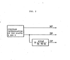
- Fig. 2 is a diagram explanatory of the operation of a tooth profile forming pulse distributor in the cutting of a helical crowning gear.
- Fig. 1 illustrates the arrangement of the principal part of an embodiment of the present invention as being applied to a numerical-control gear hobbing machine.
- reference numeral 100 indicates a bed of the gear hobbing machine and 101 a table pivotally mounted on the bed 100, on the top surface of which a gear blank can be mounted.
- the table 101 is driven by a motor 102 (the drive shaft of which will hereinafter be fererred to as the shaft C) and its ratoational position is detected by a position detector 103 and fed back to a C-shaft servo unit 104, by which the table is controlled in position.
- a ram 106 On the bed 100 is mounted a ram 106 which is driven by a motor 105 (the drive shaft of which will hereinafter be referred to as the shaft Z) to be movable up and down and its vertical position is detected by a position detector 107 and fed back to a Z-shaft servo unit 108, by which the ram is controlled in position.
- the relative vertical movement of a hob 110 and a gear blank is performed by vertical movement of the ram 106 in this embodiment but it may also be effected by vertical movement of the table 101.
- a fixed table 109 On the top of the ram 106 is provided a fixed table 109, on which is palced a horizontal slide rest 111 for cross feeding the hob 110.
- the horizontal slide rest 111 is movable back and forth by a motor 112 (the drive shaft of which will hereinafter be referred to as the shaft X) and its position is detected by a position detector 113 and fed back to an X-shaft servo unit 114, by which the slide rest is controlled in position.
- a hob mount 115 On the horizontal slide rest 111 is provided a hob mount 115, and the hob 110 installed thereon is driven by a spindle motor 117 (the drive shaft will hereinafter be referred to as the shaft T) mounted on an upper fixed table 116.
- the spindle motor 117 is speed controlled by a servo unit 118.
- a pulse coder 119 is mounted on the shaft T and a pulse signal synchronized with the rotation of the hob 118 is supplied to each part.
- the hob mount 115 is adapted so that it can turn in a vertical plane parallel to the hob shaft, and this turn is performed by a motor 120 (the drive shaft of which will hereinafter be referred to as the shaft B) and its angle of turn is detected by a position detector 121 and fed back to a B-shaft servo unit 122.
- command data 150 is decoded by a decoder 151; a revolving speed command for the spindle motor 17 is provided to the T-shaft servo unit 118; data on the number of teeth of a gear to be obtained is provided to a synchronization control pulse distributor 152; and data on the teeth profile is provided to a teeth profile forming pulse distributor 153.
- the synchronization control pulse distributor 152 performs such a pulse distribution that the number of the distribution pulses to the shaft C is given by the following expression:
- the tooth profile forming pulse distributor 153 performs the following pulse distribution in accordance with the shape of the gear to be obtained: (1) Straight gear (Spur gear)
- the pulse distribution is performed so that the shaft Z may reach a specified feed rate.
- either one of the pulse coder 119 and a pulse generator 155 is selected by changing over a gate 154 depending on whether the feed rate of the shaft Z is selected to be a feed rate proportional to the revolution of the cutter, mm(deg)/rev, or a feed rate perminute, mm(deg)/min. This applies to the cutting of the following gears of other kinds.
- pulses are distributed between the shafts Z and C in a manner to satisfy the relation given by the following expression:
- a circular interpolation of a radius corresponding to the amount of crowning is performed by the shafts X and Z first and then the amount of movement of the shaft C, CP, which satisfies the relationship of expression (2) is computed from the resulting amount of movement of the shaft Z, ZP, thereby obtaining distribution pulses to the shafts X, Z and C.
- the distribution pulses to the shaft C are added together by an adder 156 to obtain a command pulse, which is applied to the C-shaft servo unit 104. That is, the synchronization control pulse distributor 152 produces distribution pulses necessary for cutting a spur gear of the same number of teeth as the gear to be cut, and the tooth profile forming pulse distributor 153 procudes distribution pulses for additional revolution of the shaft C which is required according to the tooth profile and other distribution pulses.
- the C-shaft motor is revolved driven by the output pulses of the synchronization control pulse distributor 152, and since this revolution is synchronized with the hob shaft (the shaft T), no trouble will arise even if the feed of the shaft Z is stopped. In other words, stoppage of the vertical movement of the hob 110 or a change of its feed rate can easily by achieved during cutting. It is also possible, of course, to change the feed rates of the shafts B and X other than the shaft Z.
Landscapes
- Engineering & Computer Science (AREA)
- Mechanical Engineering (AREA)
- Human Computer Interaction (AREA)
- Manufacturing & Machinery (AREA)
- Physics & Mathematics (AREA)
- General Physics & Mathematics (AREA)
- Automation & Control Theory (AREA)
- Gear Processing (AREA)
- Numerical Control (AREA)
- Automatic Control Of Machine Tools (AREA)
Applications Claiming Priority (2)
| Application Number | Priority Date | Filing Date | Title |
|---|---|---|---|
| JP56082381A JPS57211419A (en) | 1981-05-29 | 1981-05-29 | Numerical control machine tool |
| JP82381/81 | 1981-05-29 |
Publications (3)
| Publication Number | Publication Date |
|---|---|
| EP0079965A1 true EP0079965A1 (de) | 1983-06-01 |
| EP0079965A4 EP0079965A4 (de) | 1986-01-28 |
| EP0079965B1 EP0079965B1 (de) | 1989-05-24 |
Family
ID=13772996
Family Applications (1)
| Application Number | Title | Priority Date | Filing Date |
|---|---|---|---|
| EP82901613A Expired EP0079965B1 (de) | 1981-05-29 | 1982-05-26 | Numerisch gesteuerte vorrichtung zum bearbeiten von zahnrädern |
Country Status (6)
| Country | Link |
|---|---|
| US (1) | US4585377A (de) |
| EP (1) | EP0079965B1 (de) |
| JP (1) | JPS57211419A (de) |
| KR (1) | KR860001207B1 (de) |
| DE (1) | DE3279707D1 (de) |
| WO (1) | WO1982004210A1 (de) |
Cited By (6)
| Publication number | Priority date | Publication date | Assignee | Title |
|---|---|---|---|---|
| GB2145846A (en) * | 1983-08-09 | 1985-04-03 | Honda Motor Co Ltd | Helical gear grinding machine |
| EP0140831A1 (de) * | 1983-10-18 | 1985-05-08 | Maag-Zahnräder und -Maschinen Aktiengesellschaft | Verfahren und Anordnung zum Beseitigen der Zahnflanken-Welligkeit auf Zahnradproduktionsmaschinen |
| FR2587253A1 (fr) * | 1985-09-17 | 1987-03-20 | Pfauter Hermann Gmbh Co | Procede d'usinage des flancs de roues dentees par decolletage en developpante et dispositif pour la realisation de ce procede |
| EP0382029A1 (de) * | 1989-01-30 | 1990-08-16 | Matsushita Electric Industrial Co., Ltd. | Doppelspindel-Synchronantriebseinheit und deren Anwendung auf eine Verzahnungsmaschine |
| EP0453875A1 (de) * | 1990-04-26 | 1991-10-30 | Wera-Werk Hermann Werner GmbH & Co. | Maschine zur spanenden Metallbearbeitung |
| CN101637836B (zh) * | 2009-08-21 | 2012-09-26 | 宜昌迪森机械有限公司 | 冲床精密自动冲齿分度机 |
Families Citing this family (14)
| Publication number | Priority date | Publication date | Assignee | Title |
|---|---|---|---|---|
| JPS6031925U (ja) * | 1983-08-10 | 1985-03-04 | 本田技研工業株式会社 | 歯車加工装置 |
| JPS6053375U (ja) * | 1983-09-22 | 1985-04-15 | キヤノン株式会社 | 塗料循環装置 |
| DE3519132A1 (de) * | 1985-05-29 | 1986-12-04 | Hermann Pfauter GmbH & Co, 7140 Ludwigsburg | Verfahren zur messung und/oder regelung der lage eines bewegten, vorzugsweise drehenden bezugselementes einer werkzeugmaschine, vorzugsweise einer verzahnmaschine, abhaengig von der lage eines weiteren bewegten, vorzugsweise drehenden hauptfuehrungselementes und vorrichtung zur durchfuehrung eines solchen verfahrens |
| JPS6225302A (ja) * | 1985-07-25 | 1987-02-03 | Fanuc Ltd | 数値制御装置 |
| US4755950A (en) * | 1986-04-28 | 1988-07-05 | National Broach & Machine Company | Stock divider including a computer controlled gear locator |
| JP2761426B2 (ja) * | 1990-03-29 | 1998-06-04 | ファナック株式会社 | 数値制御装置 |
| TW405470U (en) * | 1993-01-22 | 2000-09-11 | Toyota Motor Co Ltd | Apparatus for machining and measuring a gear shape |
| US5634250A (en) * | 1995-06-28 | 1997-06-03 | 2 M Tool Co., Inc. | Hobbing accessory for vertical milling machine |
| US20020081163A1 (en) * | 2000-12-21 | 2002-06-27 | Courtney Joseph A. | Stroking speed adjustment for shaping machine |
| CN103182563A (zh) * | 2012-10-19 | 2013-07-03 | 王命标 | 数控弧齿拉齿机 |
| CN103464832B (zh) * | 2013-09-26 | 2015-12-02 | 常州驰轮精密齿轮齿条有限公司 | 多功能数控磨齿机床 |
| CN103692030A (zh) * | 2013-11-06 | 2014-04-02 | 荣成锻压机床有限公司 | 大型压力机齿轮加工的对刀装置及对刀方法 |
| CN107008979B (zh) * | 2016-11-21 | 2018-08-24 | 北京工商大学 | 一种磁流体柔轮磨削装置 |
| JP6794868B2 (ja) * | 2017-02-20 | 2020-12-02 | アイシン精機株式会社 | 複合歯切加工装置 |
Family Cites Families (5)
| Publication number | Priority date | Publication date | Assignee | Title |
|---|---|---|---|---|
| US3204532A (en) * | 1958-02-24 | 1965-09-07 | Budnick Thea | Method of controlling the relative movement of two moved bodies, and device therefor |
| US3267344A (en) * | 1963-02-04 | 1966-08-16 | Bendix Corp | Numerically controlled work and feed motor driven gear-hobber |
| JPS5813293B2 (ja) * | 1974-03-12 | 1983-03-12 | カブシキガイシヤ オオクマテツコウシヨ | スウチセイギヨホブバン |
| DE2724664C3 (de) * | 1977-06-01 | 1982-01-21 | Reishauer AG, 8000 Zürich | Einrichtung zur Erzeugung einer Zusatzdrehbewegung eines schrägverzahnten Zahnrad-Werkstücks in einer zwangslaufgesteuerten, nach dem Schraubwälzverfahren arbeitenden Zahnrad-Bearbeitungsmaschine |
| JPS5615919A (en) * | 1979-07-14 | 1981-02-16 | Kashifuji Tekkosho:Kk | Rotation-controlling device for worked article in gear cutting machine |
-
1981
- 1981-05-29 JP JP56082381A patent/JPS57211419A/ja active Granted
-
1982
- 1982-05-26 WO PCT/JP1982/000197 patent/WO1982004210A1/ja not_active Ceased
- 1982-05-26 EP EP82901613A patent/EP0079965B1/de not_active Expired
- 1982-05-26 DE DE8282901613T patent/DE3279707D1/de not_active Expired
- 1982-05-26 US US06/463,870 patent/US4585377A/en not_active Expired - Lifetime
- 1982-05-28 KR KR8202377A patent/KR860001207B1/ko not_active Expired
Cited By (7)
| Publication number | Priority date | Publication date | Assignee | Title |
|---|---|---|---|---|
| GB2145846A (en) * | 1983-08-09 | 1985-04-03 | Honda Motor Co Ltd | Helical gear grinding machine |
| EP0140831A1 (de) * | 1983-10-18 | 1985-05-08 | Maag-Zahnräder und -Maschinen Aktiengesellschaft | Verfahren und Anordnung zum Beseitigen der Zahnflanken-Welligkeit auf Zahnradproduktionsmaschinen |
| FR2587253A1 (fr) * | 1985-09-17 | 1987-03-20 | Pfauter Hermann Gmbh Co | Procede d'usinage des flancs de roues dentees par decolletage en developpante et dispositif pour la realisation de ce procede |
| EP0382029A1 (de) * | 1989-01-30 | 1990-08-16 | Matsushita Electric Industrial Co., Ltd. | Doppelspindel-Synchronantriebseinheit und deren Anwendung auf eine Verzahnungsmaschine |
| US5037252A (en) * | 1989-01-30 | 1991-08-06 | Matsushita Electric Industrial Co., Ltd. | Multi-spindle synchronous drive unit and gear cutting machine employing the same |
| EP0453875A1 (de) * | 1990-04-26 | 1991-10-30 | Wera-Werk Hermann Werner GmbH & Co. | Maschine zur spanenden Metallbearbeitung |
| CN101637836B (zh) * | 2009-08-21 | 2012-09-26 | 宜昌迪森机械有限公司 | 冲床精密自动冲齿分度机 |
Also Published As
| Publication number | Publication date |
|---|---|
| JPH027767B2 (de) | 1990-02-20 |
| KR860001207B1 (ko) | 1986-08-27 |
| WO1982004210A1 (fr) | 1982-12-09 |
| JPS57211419A (en) | 1982-12-25 |
| EP0079965A4 (de) | 1986-01-28 |
| KR830009895A (ko) | 1983-12-24 |
| DE3279707D1 (en) | 1989-06-29 |
| US4585377A (en) | 1986-04-29 |
| EP0079965B1 (de) | 1989-05-24 |
Similar Documents
| Publication | Publication Date | Title |
|---|---|---|
| EP0079965A1 (de) | Numerisch gesteuerte vorrichtung zum bearbeiten von zahnrädern | |
| US4329096A (en) | Gear cutter | |
| US5076020A (en) | Apparatus for in-situ dressing of threaded grinding wheels used in gear grinding machines | |
| EP0229894B1 (de) | Verfahren zum Schleifen der Verzahnung von Kegelrädern mit längsgekrümmten Zähnen sowie Werkzeug und Vorrichtung zur Durchführung des Verfahrens | |
| DE3134147C2 (de) | ||
| US4663721A (en) | Gear cutter | |
| US4865497A (en) | Method for machining the flanks of gears by skiving and apparatus for implementing such method | |
| KR930703112A (ko) | 베벨기어 및 하이포이드기어의 창성방법 | |
| US4212572A (en) | Gear teeth rotary-shaving or roll-finishing machine | |
| DE69110583T2 (de) | Numerische steuerung. | |
| DE3901621C2 (de) | Bearbeitungsvorrichtung | |
| EP0663256B1 (de) | Verfahren und Maschine zum Herstellen von Kronenrädern | |
| US6450740B1 (en) | Mechanical gear hob with stock divide by differential gear box | |
| CN113894549A (zh) | 一种高精度数控机床加工一体机 | |
| EP0522448B1 (de) | Verfahren und Vorrichtung zum Bearbeiten der Stirnkanten der Zähne eines Werkstückzahnrades | |
| GB2153271A (en) | Method and apparatus for producing and machining toothed wheels | |
| DE3524123A1 (de) | Verfahren und vorrichtung zum profilieren von stangenartigen werkstuecken | |
| CN112108722A (zh) | 一种全自动磨齿机装置 | |
| US4537537A (en) | Method of shaping by generating for producing profiles on workpieces, and apparatus for performing this method | |
| US4748772A (en) | Apparatus for the precision working of the tooth system of bevel gears | |
| JPH10286720A (ja) | スクリュロータのスクリュ部加工方法 | |
| JPS5813293B2 (ja) | スウチセイギヨホブバン | |
| Abood | Dynamic analysis of the cutting forces in gear hobbing | |
| JPS5933491B2 (ja) | 数値制御ホブ盤 | |
| US20020129683A1 (en) | Machine tool system |
Legal Events
| Date | Code | Title | Description |
|---|---|---|---|
| PUAI | Public reference made under article 153(3) epc to a published international application that has entered the european phase |
Free format text: ORIGINAL CODE: 0009012 |
|
| 17P | Request for examination filed |
Effective date: 19830211 |
|
| AK | Designated contracting states |
Designated state(s): DE FR GB |
|
| A4 | Supplementary search report drawn up and despatched |
Effective date: 19860128 |
|
| 17Q | First examination report despatched |
Effective date: 19871002 |
|
| GRAA | (expected) grant |
Free format text: ORIGINAL CODE: 0009210 |
|
| AK | Designated contracting states |
Kind code of ref document: B1 Designated state(s): DE FR GB |
|
| REF | Corresponds to: |
Ref document number: 3279707 Country of ref document: DE Date of ref document: 19890629 |
|
| ET | Fr: translation filed | ||
| PLBE | No opposition filed within time limit |
Free format text: ORIGINAL CODE: 0009261 |
|
| STAA | Information on the status of an ep patent application or granted ep patent |
Free format text: STATUS: NO OPPOSITION FILED WITHIN TIME LIMIT |
|
| 26N | No opposition filed | ||
| PGFP | Annual fee paid to national office [announced via postgrant information from national office to epo] |
Ref country code: FR Payment date: 19910507 Year of fee payment: 10 |
|
| PGFP | Annual fee paid to national office [announced via postgrant information from national office to epo] |
Ref country code: GB Payment date: 19910514 Year of fee payment: 10 |
|
| PG25 | Lapsed in a contracting state [announced via postgrant information from national office to epo] |
Ref country code: GB Effective date: 19920526 |
|
| GBPC | Gb: european patent ceased through non-payment of renewal fee |
Effective date: 19920526 |
|
| PG25 | Lapsed in a contracting state [announced via postgrant information from national office to epo] |
Ref country code: FR Effective date: 19930129 |
|
| REG | Reference to a national code |
Ref country code: FR Ref legal event code: ST |
|
| PGFP | Annual fee paid to national office [announced via postgrant information from national office to epo] |
Ref country code: DE Payment date: 20010522 Year of fee payment: 20 |