EP0080120A1 - Dispositif pour la fabrication d'un tube à partir d'un matériau en bande plate - Google Patents
Dispositif pour la fabrication d'un tube à partir d'un matériau en bande plate Download PDFInfo
- Publication number
- EP0080120A1 EP0080120A1 EP82110416A EP82110416A EP0080120A1 EP 0080120 A1 EP0080120 A1 EP 0080120A1 EP 82110416 A EP82110416 A EP 82110416A EP 82110416 A EP82110416 A EP 82110416A EP 0080120 A1 EP0080120 A1 EP 0080120A1
- Authority
- EP
- European Patent Office
- Prior art keywords
- web
- tube
- edge
- edge zones
- film strip
- Prior art date
- Legal status (The legal status is an assumption and is not a legal conclusion. Google has not performed a legal analysis and makes no representation as to the accuracy of the status listed.)
- Granted
Links
Images




Classifications
-
- B—PERFORMING OPERATIONS; TRANSPORTING
- B31—MAKING ARTICLES OF PAPER, CARDBOARD OR MATERIAL WORKED IN A MANNER ANALOGOUS TO PAPER; WORKING PAPER, CARDBOARD OR MATERIAL WORKED IN A MANNER ANALOGOUS TO PAPER
- B31F—MECHANICAL WORKING OR DEFORMATION OF PAPER, CARDBOARD OR MATERIAL WORKED IN A MANNER ANALOGOUS TO PAPER
- B31F1/00—Mechanical deformation without removing material, e.g. in combination with laminating
- B31F1/0003—Shaping by bending, folding, twisting, straightening, flattening or rim-rolling; Shaping by bending, folding or rim-rolling combined with joining; Apparatus therefor
- B31F1/0045—Bending or folding combined with joining
- B31F1/0048—Bending plates, sheets or webs at right angles to the axis of the article being formed and joining the edges
- B31F1/0061—Bending plates, sheets or webs at right angles to the axis of the article being formed and joining the edges for making articles of indefinite length
- B31F1/0064—Bending plates, sheets or webs at right angles to the axis of the article being formed and joining the edges for making articles of indefinite length using internal forming surfaces, on, e.g. mandrels
-
- B—PERFORMING OPERATIONS; TRANSPORTING
- B31—MAKING ARTICLES OF PAPER, CARDBOARD OR MATERIAL WORKED IN A MANNER ANALOGOUS TO PAPER; WORKING PAPER, CARDBOARD OR MATERIAL WORKED IN A MANNER ANALOGOUS TO PAPER
- B31F—MECHANICAL WORKING OR DEFORMATION OF PAPER, CARDBOARD OR MATERIAL WORKED IN A MANNER ANALOGOUS TO PAPER
- B31F5/00—Attaching together sheets, strips or webs; Reinforcing edges
- B31F5/06—Attaching together sheets, strips or webs; Reinforcing edges by adhesive tape
-
- A—HUMAN NECESSITIES
- A22—BUTCHERING; MEAT TREATMENT; PROCESSING POULTRY OR FISH
- A22C—PROCESSING MEAT, POULTRY, OR FISH
- A22C13/00—Sausage casings
- A22C2013/0066—Sausage casings casings according to the presence or absence of seams
- A22C2013/0069—Sausage casings casings according to the presence or absence of seams seamed casings, casings with at least one longitudinal seam
-
- Y—GENERAL TAGGING OF NEW TECHNOLOGICAL DEVELOPMENTS; GENERAL TAGGING OF CROSS-SECTIONAL TECHNOLOGIES SPANNING OVER SEVERAL SECTIONS OF THE IPC; TECHNICAL SUBJECTS COVERED BY FORMER USPC CROSS-REFERENCE ART COLLECTIONS [XRACs] AND DIGESTS
- Y10—TECHNICAL SUBJECTS COVERED BY FORMER USPC
- Y10T—TECHNICAL SUBJECTS COVERED BY FORMER US CLASSIFICATION
- Y10T156/00—Adhesive bonding and miscellaneous chemical manufacture
- Y10T156/10—Methods of surface bonding and/or assembly therefor
- Y10T156/1002—Methods of surface bonding and/or assembly therefor with permanent bending or reshaping or surface deformation of self sustaining lamina
- Y10T156/1007—Running or continuous length work
- Y10T156/1008—Longitudinal bending
-
- Y—GENERAL TAGGING OF NEW TECHNOLOGICAL DEVELOPMENTS; GENERAL TAGGING OF CROSS-SECTIONAL TECHNOLOGIES SPANNING OVER SEVERAL SECTIONS OF THE IPC; TECHNICAL SUBJECTS COVERED BY FORMER USPC CROSS-REFERENCE ART COLLECTIONS [XRACs] AND DIGESTS
- Y10—TECHNICAL SUBJECTS COVERED BY FORMER USPC
- Y10T—TECHNICAL SUBJECTS COVERED BY FORMER US CLASSIFICATION
- Y10T156/00—Adhesive bonding and miscellaneous chemical manufacture
- Y10T156/10—Methods of surface bonding and/or assembly therefor
- Y10T156/1002—Methods of surface bonding and/or assembly therefor with permanent bending or reshaping or surface deformation of self sustaining lamina
- Y10T156/1007—Running or continuous length work
- Y10T156/1008—Longitudinal bending
- Y10T156/1013—Longitudinal bending and edge-joining of one piece blank to form tube
Definitions
- the invention relates to a method for forming a tube from a flat web of the type mentioned in the preamble of claim 1 and to a device for carrying out the method, which is based on a device as specified in the preamble of claim 5.
- folding aids in the form of shaped shoulders or shaped heads are usually used, through which the web is bent and folded, so that the two edges of the web approach and the edge zones overlap .
- a tube with a longitudinal seam is formed by gluing the overlapping edge zones.
- These known folding aids have the disadvantage that the width of the overlap area and thus also the circumference of the tube formed cannot be controlled particularly precisely.
- the web material is also subjected to considerable mechanical stress due to the short deflection of the web on the collar edge of the shaped shoulder, with high frictional forces having to be overcome.
- a mandrel arranged in the interior of the molded tube is used for support, while a roller is pressed from the outside.
- These folding aids do not ensure exact guidance of the overlapping edge zones of the web, so that the tube formed cannot have a uniform circumference.
- the molding device known from US Pat. No. 2,856,742 consists of two mutually opposite molded parts, each of which forms an arc on an edge zone of the web from the outside. Both molded parts are arranged at a distance from each other in the direction of the hose movement.
- This known shaping device is not suitable for webs which already have an adhesive on an edge zone before the tube is formed.
- the overlapping edge zones are separated from one another only in the area between the two molded parts, so that there is a risk that the edge zones will stick to one another before the first molded part is passed.
- the method and the device are intended to prevent the web edges from twisting and to enable them to run in a straight line. The deviations from an average circumference of the hose formed should be reduced and the possibility of errors in the area of the gluing should be virtually excluded.
- a flat web is understood to mean foils, films or rectangular blanks which are made of plastic, woven fabric, nonwovens or metal such as aluminum.
- the web is made of cellulose, i.e. Cellular glass, regenerated cellulose or cellulose hydrate, from cellulose derivatives such as cellulose ether, from starch and starch derivatives or from protein substances.
- cellulose webs can be produced from viscose by coagulation, from cellulose nitrate by denitration or from cellulose esters by hydrolysis. It is also possible to form webs that are reinforced with a fiber insert into a tube.
- a paper web is coated on one or both sides with viscose and the viscose is converted into regenerated cellulose by coagulation.
- the carrier material of the film strip preferably consists of the same material as the web. It connects both marginal zones with each other, which are approached to one another by overlapping the two essentially uniformly. Film strips can be on the outside and / or inside of the molded tube. If the edge zones overlap, there is the additional possibility that the film strip can also be located between the overlapping edge zones.
- the carrier film of the film strip shows an adhesive coating on both sides, at least one of the two adhesive layers possibly having a release film, e.g. Silicone paper, if the double-sided adhesive film strip is stored on a roll.
- the separating film is then pulled off the other adhesive layer during tube forming, in particular when the flexible strip is passed through, when the unprotected adhesive layer is already connected to one edge zone of the web.
- a film strip with a one-sided adhesive layer the carrier film of which may have the function of a separating film if the carrier film is pulled off the adhesive layer after the adhesive layer has been bonded to an edge zone of the web.
- the carrier film is removed, for example, when passing through the flexible strip.
- the separating film or the carrier film is preferably pulled off in the tangential direction with respect to the shaped tube.
- the method and the device are particularly suitable for those webs or film strips that have an adhesive layer on one or both edge zones or on the surface of the film strip, or even before the overlap of the edge zones with one another or the edge zones with the film strip begins are sticky (DE-OS 30 13 320), because in this case the method or the device offers the advantage that a contact between the edge zone and the edge zone or edge zones with film strips cannot occur at the beginning of the overlap.
- the adhesive layer is applied, for example, in the form of a dispersion or solution with application rollers or nozzles. It is also possible to transfer the adhesive layer with a carrier tape, which is then peeled off. If solvents or dispersants are used for the adhesive, they are removed by the action of heat before, during or after the formation of the adhesive seam.
- thermoplastic resins which are sealable when pressure and heat are applied (US Pat. No. 2,773,773) or solutions of water-soluble cationic resins which, after hardening, form a water-insoluble adhesive seam (US Pat. No. 2,607,696).
- the web or the film strip expediently has a layer of an anchoring agent which, as an adhesion-promoting layer, is applied to one or both adhesive surfaces or even to the entire web surface before the adhesive is applied, in order to improve the adhesion between the adhesive and the adhesive surfaces.
- the web and optionally also the film strip depending on the intended use of the hose formed, can have customary coatings on the surfaces forming the later inner and outer sides of the hose. If the hose is used, for example, as an artificial sausage casing, means known per se for improving the peelability of the hose casing, dyes, a gas-impermeable plastic layer, water-repellent resins or prints can be applied to the web surface (s) and / or to the surface of the film strip.
- the means for locomotion of the web consist of conventional rollers or pairs of rollers or clips which grip the web on its two longitudinal edges and convey it in the longitudinal direction of the web, and possibly also bend and fold the web. They are arranged before and / or after the hose shaping means according to the invention. The film strip is guided to the seam in the direction of web travel.
- the essential part of the invention is the flexible strip, which is bent in cross section. It consists of a plastic with good slip properties compared to the web material or the adhesive layer or shows a coating of this material.
- the cross-sectional curvature is adaptable to the hose circumference due to the flexibility of the flexible strip. It is also possible to choose the width of the flexible strip so large that, in conjunction with an interior which is relatively small in cross section bore of the molded body results in a spiral cross-sectional shape of the flexible strip. Because of its curvature, the flexible strip is relatively stiff in the longitudinal direction compared to the transverse direction.
- the flexible strip is arranged in the longitudinal direction of the web.
- the means for connecting the overlapping edge zones of the web to form an adhesive seam for example a means for heat sealing, for curing the resins serving as an adhesive or for pressing the edge zones against one another, preferably follows directly after the strip, for example if a pressure sensitive adhesive is used.
- These means for forming the adhesive seam thus include sealing stations, heating elements or pressure rollers, which are selected and set depending on the adhesive used.
- the filling tube of a device is inserted into the tube in the direction of web travel, the filling tube opening being located after the means for producing the adhesive seam.
- the filling material is introduced into the hose under pressure or under the effect of gravity.
- a further, downstream device for portioning filled sections for example a device for clipping or a sealing station, which transports the filled sections transversely to the direction of transport sealed, and then a cutter for separating the filled sections can be arranged.
- the flexible strip shows along one of its two longitudinal edges, along both longitudinal edges and / or edges projecting from its longitudinal axis, with which one or both longitudinal edges of the folded web and / or the longitudinal edge (s) of the film strip are guided.
- the edges of the flexible strip protrude in the radial direction from the hose.
- a molded body with an essentially circular or elliptical internal bore in cross-section is arranged as an additional means for tube shaping in the region of the overlap of the edge zones of the web, in particular in the region of the complete overlap, the shaped tube being guided through the inner bore of the molded body and consequently on its outer surface is supported.
- the cross-section of the inner bore is the measure of the caliber and the shape of the hose to be manufactured.
- the inner bore expediently forms a substantially circular-cylindrical cavity, which also includes elliptical shapes. For the sake of simplicity, only the term circular or circular cylindrical is used.
- the wall of the inner bore advantageously consists of a material with good sliding properties compared to the sheet material or the material of the film strip, for example made of polytetrafluoroethylene, so that a good slip when Passing the tube or the film strip through the inner bore is guaranteed.
- an essentially circular cylindrical inner mandrel is used, optionally in addition to the shaped body with an inner bore.
- the inner mandrel is located inside the molded tube, in an area of the tube where the edge zones of the web overlap or begin to overlap with one another or with the film strip, but in any case in the area of the tube where there is a complete overlap . If a molded body with an inner bore is used, the inner mandrel is located in the region of the inner bore or extends at least with part of its length into the inner bore.
- the inner mandrel is expediently arranged “floating”, ie it can change its position in the transverse direction to the hose movement.
- the inner mandrel is fastened, for example, on one end face to one end of a rod or wire, the other end of which protrudes out of the shaped tube in the direction of the flat path and is fixed, for example, to a holder.
- the rod or wire is resilient due to its material or its thickness in the transverse direction to the path advancement and automatically returns to its starting position after a deflection transverse to the longitudinal axis of the path.
- the longitudinal axis running through the center point of the cross section of the inner mandrel is preferably equal to the longitudinal axis of the shaped body that passes through the center point of the cross section its inner bore runs.
- the flexible strip which is attached with its protruding edge or with its protruding edges to the outer surface of the inner mandrel and / or inner surface of the inner bore, e.g. in a slot, a groove or a groove on the surfaces of the inner mandrel or the inner bore. It is also possible to attach the flexible strip exclusively or additionally to a holder at its first end protruding from the molded tube in the direction of the flat web.
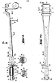
- FIG. 1 shows an embodiment of the device in side view, partly in section, in which the tube formed has overlapping edge zones of the web
- FIG. 2 a shows the parts of the device shown in FIG. 1 which are essential to the invention
- Fig. 3 shows the device parts of Fig. 2a in section along the line III-III
- FIG. 4 shows a variant of the device of FIG. 1, the adhesive layer being applied by means of a film strip
- FIG. 4a shows the device of FIG. 4 in a top view.
- FIG. 8 to 11 show further embodiments of the device parts shown in FIG. 2 in section along the line III-III, with which the edge zones are approached to one another and one or two film strips cover both edge zones,
- FIG. 12 to 15 show further embodiments of the device parts shown in FIG. 2 in section along the line III-III, with which the edge zones overlap and are covered with one or two film strips,
- 5a to 15a show embodiments of hoses in section, with the device parts of each 4 to 15 have been produced.
- a flat web 1 is fed via a deflection and guide roller 2 to a shaped body 3 with an inner bore 4 which is circular in cross section.
- the application of the adhesive layer 22 in the region of an edge zone 6 of the web 1 takes place with the device 28 consisting of the rollers 26a and 26b and the tub 28 containing the adhesive dispersion or adhesive solution 27.
- the flexible strip 5 is arranged between the overlapping edge zones 6 of the web 1 (FIG. 3).
- the edge zones 6 are completely overlapped in the interior of the molded body 3.
- the molded body 3 with the inner bore 4 is partially enlarged (FIGS. 2a and 3). It consists of two halves 3a and 3b joined together.
- the flexible Stripes - fen 5 is provided with his protruding edges 17a and 17b on Inner mandrel 7 or attached to the inner bore 4 of the molded body 3.
- the first end 16a of the flexible strip 5 protrudes in the direction of the flat path from the inner bore 4 of the molded body 3 and is located before the beginning of the overlap area.
- the two edge zones 6 of the web 1 formed into a tube 14 are guided through the two projecting edges 17a and 17b of the flexible strip 5 along a straight line extending parallel to the direction of travel.
- the edges 17a and 17b are fastened in grooves 18 on the circumferential surface of the inner mandrel 7 and on the surface of the inner bore.
- the edge zones 6 of the web 1 are held at a distance from one another by the flexible strip 5 and only come into contact with one another when the web has reached the second end 16b of the flexible strip 5. In the embodiment of FIG. 2a, this second end 16b is still inside the inner bore 4. It is also possible that the second end 16b is arranged at the outlet of the inner bore 4 (FIG. 2b) or even up to shortly before the contact roller 10 extends (Fig. 2c).
- the web 1 is unwound from a roll 21 and a film strip 19 with adhesive layer 22 is unwound from a roll 20 and guided with deflection rolls 2 in the direction of the web travel.
- the adhesive layer 22 is first applied to one edge zone 6 of the web 1, then that as a protection and separation paper strips 19 pulled off tangentially and deflected by the roller 23.
- the flexible strip 5 which has the same cross section as in the previous figures, prevents contact between the adhesive layer 22, from which the film strip 19 is peeled off, and the overlapping adhesive-free edge zone of the web-1. If a double-sided adhesive film strip is used in FIG. 4, the separating film then additionally present, which covers one of the two adhesive layers, must be pulled off tangentially in an analogous manner.
- the flexible strip 5 shows only a protruding edge 17b, which is fastened to the inner bore 4 of the molded body 3 in a groove or groove 18.
- the cross section shown in FIG. 5 a of the glued hose 11 with the adhesive seam 13 also results with the device parts shown in FIG. 3. With 29 a joint is designated, which serves to open the part 3a of the molded body 3.
- the flexible strip 5 shows two projecting edges 17a and 17b, which are fastened to the inner mandrel 7 and to the inner bore 4 of the molded body 3, respectively.
- the relatively large width of the flexible strip 5 results in a further overlap of the edge zones of the hoses 11 shown in cross section in FIGS. 6a and 7a in comparison to the hose cross section shown in FIG. 5a.
- the film strip 19 is guided in a recess 25 of the inner mandrel 7.
- a recess 25 can also be provided in the inner surface of the inner bore 4 for guiding the film strip (not shown).
- the flexible strip 5 shows a projecting first edge 17c which extends along its longitudinal axis and which is fastened to the inner bore 4 of the molded body 3 in FIGS. 8 and 9 and to the peripheral surface of the inner mandrel 7 in FIG. 10 and 11 ends in a cross-sectionally U-shaped profile 24, the two legs of the profile 24 being fastened to the peripheral surface of the inner mandrel 7.
- the flexible strip 5 additionally shows on its two longitudinal edges two further protruding edges 17a and 17b, both of which protrude from the flexible strip 5 approximately in the same direction and opposite to the first edge 17c.
- FIGS. 5a, 6a, 7a and 12a, 13a, 14a and 15a show overlapping edge zones 6,
- the hoses of FIGS. 8a, 9a, 10a and 11a show edge zones 6 which are approximated by an abutment and / or external film strips 19 covering both edge zones 6 are connected to one another with adhesive layer 22.
Landscapes
- Engineering & Computer Science (AREA)
- Mechanical Engineering (AREA)
- Shaping Of Tube Ends By Bending Or Straightening (AREA)
- Making Paper Articles (AREA)
- Liquid Developers In Electrophotography (AREA)
- Superconductors And Manufacturing Methods Therefor (AREA)
- Float Valves (AREA)
Priority Applications (1)
| Application Number | Priority Date | Filing Date | Title |
|---|---|---|---|
| AT82110416T ATE18738T1 (de) | 1981-11-20 | 1982-11-11 | Vorrichtung zur bildung eines schlauches aus einer flachen bahn. |
Applications Claiming Priority (2)
| Application Number | Priority Date | Filing Date | Title |
|---|---|---|---|
| DE3145967 | 1981-11-20 | ||
| DE19813145967 DE3145967A1 (de) | 1981-11-20 | 1981-11-20 | Verfahren und vorrichtung zur bildung eines schlauches aus einer flachen bahn |
Publications (2)
| Publication Number | Publication Date |
|---|---|
| EP0080120A1 true EP0080120A1 (fr) | 1983-06-01 |
| EP0080120B1 EP0080120B1 (fr) | 1986-03-26 |
Family
ID=6146781
Family Applications (1)
| Application Number | Title | Priority Date | Filing Date |
|---|---|---|---|
| EP82110416A Expired EP0080120B1 (fr) | 1981-11-20 | 1982-11-11 | Dispositif pour la fabrication d'un tube à partir d'un matériau en bande plate |
Country Status (7)
| Country | Link |
|---|---|
| US (1) | US4478670A (fr) |
| EP (1) | EP0080120B1 (fr) |
| JP (1) | JPS58131034A (fr) |
| AT (1) | ATE18738T1 (fr) |
| CA (1) | CA1194772A (fr) |
| DE (2) | DE3145967A1 (fr) |
| FI (1) | FI823966L (fr) |
Families Citing this family (33)
| Publication number | Priority date | Publication date | Assignee | Title |
|---|---|---|---|---|
| DE3343635A1 (de) * | 1983-12-02 | 1985-06-13 | Hoechst Ag, 6230 Frankfurt | Folie aus faserverstaerkter regenerierter cellulose mit gasundurchlaessiger schicht zur herstellung von schlauchhuellen |
| US4533421A (en) * | 1984-04-25 | 1985-08-06 | Pattridge Post Tension, Inc. | Method for making a lap seam extruded tendon |
| US4849042A (en) * | 1985-09-03 | 1989-07-18 | Rainbow Star Licensing S.A. | Ornament production |
| CA1232451A (fr) * | 1985-09-03 | 1988-02-09 | James D. Mancel | Production d'articles decoratifs |
| US5026453A (en) * | 1985-09-03 | 1991-06-25 | Rainbow Star Licensing, S.A. | Apparatus for ornament production |
| US4855009A (en) * | 1985-09-03 | 1989-08-08 | Rainbow Star Licensing S.A. | Ornament production apparatus |
| US5030307A (en) * | 1985-09-04 | 1991-07-09 | Rainbow Star Licensing, S.A. | Method of ornament production |
| DE3536172A1 (de) * | 1985-10-10 | 1987-04-16 | Bosch Gmbh Robert | Verfahren und vorrichtung zum herstellen einer stossnaht mit deckband an einem rohr aus einer mehrschicht-packstoffbahn |
| DE3538702A1 (de) * | 1985-10-31 | 1987-05-07 | Hoechst Ag | Sauerstoff- und wasserdampfundurchlaessige folie zur herstellung geraffter schlauchhuellen, insbesondere wursthuellen |
| DE3542256A1 (de) * | 1985-11-29 | 1987-06-04 | Hoechst Ag | Vorrichtung zum kontinuierlichen schweissen bzw. siegeln von naehten von kunststoff-folien |
| DE3631669A1 (de) * | 1986-09-18 | 1988-03-24 | Hoechst Ag | Verstaerkungsfreie folie aus cellulose |
| US4875960A (en) * | 1987-03-14 | 1989-10-24 | Hokkai Can Co., Ltd. | Apparatus and method for manufacturing tubular member |
| US4944972A (en) * | 1987-12-31 | 1990-07-31 | American National Can Company | Coextrusion apparatus, methods, and related films and packages |
| US5284687A (en) * | 1987-12-31 | 1994-02-08 | American National Can Company | Coextrustion apparatus, methods, and related films and packages |
| DE8804813U1 (de) * | 1988-04-13 | 1988-06-09 | Hoechst Ag, 65929 Frankfurt | Schlauchhülle, insbesondere künstliche Wursthülle, mit längsaxialem Klebeband |
| US4956963A (en) * | 1988-11-14 | 1990-09-18 | Nordson Corporation | Method of sealing a shrink wrap package |
| US5169481A (en) * | 1990-03-16 | 1992-12-08 | Philip Morris Incorporated | Apparatus making thin laminate structures and forming the structures into lightweight, thin-walled tubes |
| US5376202A (en) * | 1993-02-08 | 1994-12-27 | Maresh; Joseph D. | Method of forming an adhesive tape tube |
| FR2702414B1 (fr) * | 1993-03-12 | 1996-07-05 | Helverep Sa | Procédé de fabrication en continu de corps tubulaires de boîtes notamment en carton. |
| US5421371A (en) * | 1993-04-19 | 1995-06-06 | Nmc Of North America, Inc. | Multi-layered bonded closure system for foam tubes or profiles |
| US6502616B1 (en) * | 2000-06-14 | 2003-01-07 | Scott Whasuk Row | Apparatus and method for folding and dispensing tape |
| US20030063968A1 (en) * | 2001-10-01 | 2003-04-03 | Zaun Richard D. | Apparatus for transporting and filling freight containers |
| GB2381261B (en) * | 2001-10-29 | 2004-02-04 | Field Group Plc | Tubes and tubular containers |
| US7153124B2 (en) * | 2002-08-09 | 2006-12-26 | The Boeing Company | Preforming thermoplastic ducts |
| DE10307678A1 (de) * | 2003-02-14 | 2004-09-02 | Windmöller & Hölscher Kg | Schlauch sowie Vorrichtung und Verfahren zur Herstellung desselben |
| US20090280221A1 (en) * | 2008-05-07 | 2009-11-12 | Reg Macquarrie | Vegetable casing film and method for production of tubular sausage casings |
| US9308703B2 (en) | 2008-11-04 | 2016-04-12 | Shurtape Technologies, Llc | Device for making corrugated metallic foil tape |
| US20100112294A1 (en) | 2008-11-04 | 2010-05-06 | Shurtape Technologies, Inc. | Corrugated metallic foil tape |
| US8261558B2 (en) | 2009-06-25 | 2012-09-11 | Nomaco Inc. | Self-adjusting insulation, including insulation particularly suited for pipe or duct |
| DE102009036556A1 (de) * | 2009-08-10 | 2011-02-17 | Windmöller & Hölscher Kg | Verfahren und Vorrichtung zur Herstellung eines Sacks oder eines Beutels mit Vliesmaterial sowie Sack oder Beutel, welcher Vliesmaterial umfasst |
| WO2013170250A1 (fr) | 2012-05-11 | 2013-11-14 | Nomaco Inc. | Systèmes d'isolation faisant appel à des caractéristiques d'expansion pour isoler des contenants allongés soumis à des fluctuations de température extrêmes, et composants et procédés connexes |
| EP2845499B1 (fr) * | 2012-10-31 | 2019-10-16 | Japan Tobacco, Inc. | Machine à fabriquer des tubes de papier, procédé de fabrication de ces derniers et tube de papier fabriqué par ledit procédé de fabrication |
| WO2017055556A1 (fr) * | 2015-09-30 | 2017-04-06 | Poly-Clip System Gmbh & Co. Kg | Matériau d'enserrage scellable |
Citations (5)
| Publication number | Priority date | Publication date | Assignee | Title |
|---|---|---|---|---|
| BE630355A (fr) * | ||||
| US2285263A (en) * | 1942-06-02 | Forming tool | ||
| GB696864A (en) * | 1950-11-30 | 1953-09-09 | American Viscose Corp | Apparatus for making stuffed products, for example sausages |
| GB881638A (en) * | 1960-02-12 | 1961-11-08 | Rhenopack G M B H | Machine for the manufacture of thermo-plastic tubes |
| FR2275301A1 (fr) * | 1974-05-31 | 1976-01-16 | Yoshino Kogyosho Co Ltd | Machine pour la fabrication automatique de tubes en matiere plastique |
Family Cites Families (7)
| Publication number | Priority date | Publication date | Assignee | Title |
|---|---|---|---|---|
| FR630355A (fr) * | 1925-07-14 | 1927-12-01 | Raccord pour établir des communications sur conduites tubulaires | |
| BE534294A (fr) * | 1954-09-04 | |||
| US2856742A (en) * | 1954-12-27 | 1958-10-21 | American Viscose Corp | Guide for sausage stuffing machine |
| US3066063A (en) * | 1957-10-17 | 1962-11-27 | American Can Co | Method of forming longitudinally extending side seams in a tubular container |
| US3912568A (en) * | 1969-07-07 | 1975-10-14 | Toyo Seikan Kaisha Ltd | Method of manufacturing drums of metal cans |
| US3593483A (en) * | 1969-07-28 | 1971-07-20 | Kartridg Pak Co | Method of forming a package with easy opening device |
| CH642590A5 (de) * | 1979-07-26 | 1984-04-30 | Tetra Pak Dev | Verfahren und einrichtung zum verbinden der kantenbereiche von bahnen, insbesondere bei der herstellung eines schlauches. |
-
1981
- 1981-11-20 DE DE19813145967 patent/DE3145967A1/de not_active Withdrawn
-
1982
- 1982-11-09 CA CA000415209A patent/CA1194772A/fr not_active Expired
- 1982-11-11 AT AT82110416T patent/ATE18738T1/de not_active IP Right Cessation
- 1982-11-11 DE DE8282110416T patent/DE3270159D1/de not_active Expired
- 1982-11-11 EP EP82110416A patent/EP0080120B1/fr not_active Expired
- 1982-11-12 US US06/441,226 patent/US4478670A/en not_active Expired - Fee Related
- 1982-11-18 FI FI823966A patent/FI823966L/fi not_active Application Discontinuation
- 1982-11-19 JP JP57202183A patent/JPS58131034A/ja active Pending
Patent Citations (5)
| Publication number | Priority date | Publication date | Assignee | Title |
|---|---|---|---|---|
| BE630355A (fr) * | ||||
| US2285263A (en) * | 1942-06-02 | Forming tool | ||
| GB696864A (en) * | 1950-11-30 | 1953-09-09 | American Viscose Corp | Apparatus for making stuffed products, for example sausages |
| GB881638A (en) * | 1960-02-12 | 1961-11-08 | Rhenopack G M B H | Machine for the manufacture of thermo-plastic tubes |
| FR2275301A1 (fr) * | 1974-05-31 | 1976-01-16 | Yoshino Kogyosho Co Ltd | Machine pour la fabrication automatique de tubes en matiere plastique |
Also Published As
| Publication number | Publication date |
|---|---|
| JPS58131034A (ja) | 1983-08-04 |
| FI823966A7 (fi) | 1983-05-21 |
| FI823966L (fi) | 1983-05-21 |
| DE3270159D1 (en) | 1986-04-30 |
| CA1194772A (fr) | 1985-10-08 |
| US4478670A (en) | 1984-10-23 |
| EP0080120B1 (fr) | 1986-03-26 |
| ATE18738T1 (de) | 1986-04-15 |
| DE3145967A1 (de) | 1983-06-01 |
| FI823966A0 (fi) | 1982-11-18 |
Similar Documents
| Publication | Publication Date | Title |
|---|---|---|
| EP0080120B1 (fr) | Dispositif pour la fabrication d'un tube à partir d'un matériau en bande plate | |
| DE3447442C2 (fr) | ||
| EP0072779B1 (fr) | Dispositif pour appliquer une bande adhésive sur le bord d'une plaque | |
| DE2657695C3 (de) | Folienschlauch zur Bewässerung sowie Verfahren zu dessen Herstellung | |
| DE2854586A1 (de) | Verfahren und vorrichtung zur herstellung von kunststoffhuelsen | |
| EP3946918A1 (fr) | Fabrication de pailles en papier | |
| WO2020127545A1 (fr) | Dispositif pour produire des produits en forme de tiges de l'industrie du tabac | |
| EP0062812B1 (fr) | Procédé de revêtement de l'intérieur d'un tuyau et dispositif pour la mise en oeuvre dudit procédé | |
| DE2635526A1 (de) | Verfahren und vorrichtung zum verarbeiten von poroesem huellmaterial fuer rauchwaren | |
| EP0100495A1 (fr) | Boyau à saucisses plissé et procédé pour sa fabrication | |
| DE2155667C3 (de) | QuerstromfUter und Verfahren und Vorrichtung zu dessen Herstellung | |
| EP0093326B1 (fr) | Boyau de saucisses plissé et procédé de sa fabrication | |
| DE1093546B (de) | Verfahren zum Herstellen von innen glatten Schlaeuchen aus thermoplastischem Kunststoff mit einer Stuetzwendel nach der Methode des Wickelns | |
| EP2067731B1 (fr) | Tube d'enroulement ou douille d'enroulement pour bandes de matériaux | |
| DE1504671A1 (de) | Verfahren zum Flachlegen von Schlauchfolien kreisfoermigen Querschnitts | |
| DE2721242C2 (de) | Vorrichtung zum kontinuierlichen schraubenförmigen Wickeln von flexiblen Schläuchen aus einem Band aus flexiblem Material | |
| DE3603748A1 (de) | Vorrichtung zum herstellen eines kontinuierlichen roehrchens der tabakverarbeitenden industrie | |
| EP0267473B1 (fr) | Procédé et dispositif pour plisser des enveloppes tubulaires, en particulier des boyaux de saucisse | |
| DE3713479A1 (de) | Schlauch, insbesondere kuenstliche wursthuelle, aus miteinander verbundenen abschnitten | |
| DE19501668C1 (de) | Verfahren und Vorrichtung zum Abziehen eines aus einem Blasfolienextruder austretenden Folienschlauches | |
| DE2402406A1 (de) | Tubenfoermiger behaelter, verfahren zur herstellung dieses behaelters und vorrichtung zur durchfuehrung eines solchen verfahrens | |
| DE359009C (de) | Verfahren zur Herstellung von Zargen fuer Pappschachteln | |
| DE1504918A1 (de) | Verfahren und Vorrichtung zum Herstellen von Rohrstraengen oder Behaelterruempfen aus Kunststoff | |
| DE1479930C (de) | Verfahren und Vorrichtung zum kontinuierlichen Herstellen eines Rohres aus einer flachen Bahn eines biegsamen, schweißbaren Materials | |
| DE102024101817A1 (de) | Hohlröhrchenherstellung |
Legal Events
| Date | Code | Title | Description |
|---|---|---|---|
| PUAI | Public reference made under article 153(3) epc to a published international application that has entered the european phase |
Free format text: ORIGINAL CODE: 0009012 |
|
| AK | Designated contracting states |
Designated state(s): AT BE CH DE FR GB IT LI LU NL SE |
|
| 17P | Request for examination filed |
Effective date: 19831107 |
|
| ITF | It: translation for a ep patent filed | ||
| GRAA | (expected) grant |
Free format text: ORIGINAL CODE: 0009210 |
|
| AK | Designated contracting states |
Kind code of ref document: B1 Designated state(s): AT BE CH DE FR GB IT LI LU NL SE |
|
| REF | Corresponds to: |
Ref document number: 18738 Country of ref document: AT Date of ref document: 19860415 Kind code of ref document: T |
|
| REF | Corresponds to: |
Ref document number: 3270159 Country of ref document: DE Date of ref document: 19860430 |
|
| ET | Fr: translation filed | ||
| PGFP | Annual fee paid to national office [announced via postgrant information from national office to epo] |
Ref country code: AT Payment date: 19861030 Year of fee payment: 5 |
|
| PG25 | Lapsed in a contracting state [announced via postgrant information from national office to epo] |
Ref country code: LU Free format text: LAPSE BECAUSE OF NON-PAYMENT OF DUE FEES Effective date: 19861130 |
|
| PGFP | Annual fee paid to national office [announced via postgrant information from national office to epo] |
Ref country code: NL Payment date: 19861130 Year of fee payment: 5 |
|
| PLBE | No opposition filed within time limit |
Free format text: ORIGINAL CODE: 0009261 |
|
| STAA | Information on the status of an ep patent application or granted ep patent |
Free format text: STATUS: NO OPPOSITION FILED WITHIN TIME LIMIT |
|
| 26N | No opposition filed | ||
| PG25 | Lapsed in a contracting state [announced via postgrant information from national office to epo] |
Ref country code: AT Effective date: 19871111 |
|
| PG25 | Lapsed in a contracting state [announced via postgrant information from national office to epo] |
Ref country code: SE Effective date: 19871112 |
|
| PG25 | Lapsed in a contracting state [announced via postgrant information from national office to epo] |
Ref country code: LI Effective date: 19871130 Ref country code: CH Effective date: 19871130 Ref country code: BE Effective date: 19871130 |
|
| BERE | Be: lapsed |
Owner name: HOECHST A.G. Effective date: 19871130 |
|
| PG25 | Lapsed in a contracting state [announced via postgrant information from national office to epo] |
Ref country code: NL Effective date: 19880601 |
|
| NLV4 | Nl: lapsed or anulled due to non-payment of the annual fee | ||
| GBPC | Gb: european patent ceased through non-payment of renewal fee | ||
| PG25 | Lapsed in a contracting state [announced via postgrant information from national office to epo] |
Ref country code: FR Free format text: LAPSE BECAUSE OF NON-PAYMENT OF DUE FEES Effective date: 19880729 |
|
| REG | Reference to a national code |
Ref country code: CH Ref legal event code: PL |
|
| PG25 | Lapsed in a contracting state [announced via postgrant information from national office to epo] |
Ref country code: DE Effective date: 19880802 |
|
| REG | Reference to a national code |
Ref country code: FR Ref legal event code: ST |
|
| PG25 | Lapsed in a contracting state [announced via postgrant information from national office to epo] |
Ref country code: GB Effective date: 19881121 |
|
| ITTA | It: last paid annual fee | ||
| EUG | Se: european patent has lapsed |
Ref document number: 82110416.3 Effective date: 19880913 |