EP0081130A2 - Système de détente électrique pour armes à feu - Google Patents
Système de détente électrique pour armes à feu Download PDFInfo
- Publication number
- EP0081130A2 EP0081130A2 EP82110745A EP82110745A EP0081130A2 EP 0081130 A2 EP0081130 A2 EP 0081130A2 EP 82110745 A EP82110745 A EP 82110745A EP 82110745 A EP82110745 A EP 82110745A EP 0081130 A2 EP0081130 A2 EP 0081130A2
- Authority
- EP
- European Patent Office
- Prior art keywords
- trigger
- contact
- lever
- contact lever
- switch
- Prior art date
- Legal status (The legal status is an assumption and is not a legal conclusion. Google has not performed a legal analysis and makes no representation as to the accuracy of the status listed.)
- Withdrawn
Links
Images


Classifications
-
- F—MECHANICAL ENGINEERING; LIGHTING; HEATING; WEAPONS; BLASTING
- F41—WEAPONS
- F41A—FUNCTIONAL FEATURES OR DETAILS COMMON TO BOTH SMALLARMS AND ORDNANCE, e.g. CANNONS; MOUNTINGS FOR SMALLARMS OR ORDNANCE
- F41A19/00—Firing or trigger mechanisms; Cocking mechanisms
- F41A19/58—Electric firing mechanisms
- F41A19/59—Electromechanical firing mechanisms, i.e. the mechanical striker element being propelled or released by electric means
Definitions
- the invention relates to an electric trigger device for firearms, with an electrical switch which can be actuated by means of the trigger tongue and which is part of a circuit arrangement for triggering the shot and has a spring-loaded, pivotably mounted contact carrier which is connected to the trigger trigger by a spring-loaded trigger member can also be deflected from its rest position in order to bring its contact to a stationary counter-contact to the system.
- Such an electrical trigger device is known from DE-OS 24 04 053.
- the trigger tongue is attached to a pivotable lever which has a fork-shaped end with which it engages around the end of another lever, which is the control lever of a switch with a jumping character.
- This switch has a contact-carrying rocker switch, which closes one of two working contacts in each of its two positions.
- the lever carrying the trigger tongue is attached to a leaf spring, the pretension of which is adjustable to adjust the trigger weight.
- the known trigger device therefore has the characteristic of a pressure point trigger, in which the lever carrying the trigger tongue must first be pivoted with the set force until it comes to rest on the lever of the toggle switch, the actuation of which requires additional force.
- the invention has for its object to provide an electrical trigger device of the type described so that it has the perfect - characteristic of a pressure point trigger, in which after reaching the pressure point only a very small trigger path must be carried out against increased resistance and a firm stop is reached at the end of this passage, just as is the case with the conventional mechanical extraction devices.
- the trigger member is formed by a trigger rod which is displaceable in its longitudinal direction and the contact carrier is formed by a non-armed contact lever which extends substantially perpendicularly to the trigger rod and in that the trigger rod with its rear end in the trigger direction on the short arm of the contact lever, whereas the contact is arranged on the long arm of the contact lever.
- the trigger rod By using an essentially rectilinearly displaceable trigger rod, the end of which acts on the arm of a lever carrying the contact, a very simple mechanical design of the trigger device is achieved, which ensures that the links of the trigger device can be stored essentially without play and without any noteworthy, mutual displacements work together so that no undesired changes in the force relationships can occur in the course of the trigger movement.
- the trigger rod is displaceable against a defined spring load until it comes into engagement with the contact lever at its end. Then, while overcoming the additional spring force loading the contact lever, the contact lever is pivoted until the switch is closed and the shot is thereby triggered.
- the arrangement can easily be made so that the pull-through distance after reaching the pressure point is only very small, because a very strong translation of the movement of the trigger rod can be achieved by the choice of the ratio of the short and long lever arms. This translation can be achieved at the same time that the spring force acting on the contact lever remains practically constant when the contact lever is pivoted. If the contact lever is pivoted so far that its contact has come to rest on the stationary counter contact, a further movement of the trigger tongue is no longer possible, just as is the case with mechanical trigger devices after the shot is fired.
- an electrical trigger device is created by the invention, which ideally the Forde requirements that the shooter places on a trigger trigger.
- the contact lever is loaded by a helical tension spring which engages the contact lever essentially perpendicular to its direction near its center of gravity and at the same time pulls bearing pins attached to the contact lever into bearing shells which are open on one side and applies the long arm of the contact lever to a stationary replacement bearing.
- This embodiment of the trigger device according to the invention has the advantage that no complicated construction with inserted axes and the like is required for mounting the contact lever, but the pivot pin as well as the open bearing shells can be molded onto the contact lever or a switch housing or the like and still A completely play-free storage of the contact lever is achieved, which is essential for maintaining short trigger distances and a precisely defined shot release.
- the contact lever can be designed on two sides and engage the helical tension spring on its long arm.
- the "arm" of the contact lever meant the distance between the pivot axis and the point of application of the trigger rod or the position of the contact, so that these arms can physically collapse on the same side of the pivot axis. In the two-sided design of the contact lever just mentioned, however, these arms lie on both sides of the pivot axis.
- the contact lever is advantageously mounted in a switch housing with walls essentially parallel to the contact lever.
- This switch housing also accommodates the spring loading the contact lever and has, at one end, the stationary counter-contact opposite one another and a bearing for the rest position of the contact lever at such a distance that the long arm of the contact lever engages between the counter-contact and bearing with little play .
- the contact lever can be simply inserted into such a switch housing and, as already mentioned above, is then held securely and without play by the helical tension spring loading the contact lever.
- the arrangement of the abutment for the rest position of the contact lever and the mating contact simultaneously ensures that a precisely defined traverse path is maintained after the pressure point is reached.
- the switch housing can be fastened in the section of the weapon housing adjacent to the rear end of the trigger guard in such a way that the pivot point of the contact lever is at the upper end of the switch housing and the switch housing is firmly supported on the weapon housing by the upper end of its rear side. At this point, the switch housing takes up little space in the weapon and is also easy to mount there.
- the support of the upper end of the switch housing on the weapon housing is approximately in the extension of the trigger rod, so that the switch housing is under no circumstances under the pressure of the trigger rod can dodge or give way, so that in this respect, compliance with defined conditions when firing the shot is guaranteed.
- the good support of the switch housing on the weapon housing can be promoted in that the switch housing has a rear wall which is inclined outwards at the top and is pulled against a correspondingly inclined wall of the weapon housing by a fastening screw acting on the floor. In this way, by using only a single fastening screw, which is also accessible from the underside of the weapon housing, an absolutely secure fastening of the switch housing is achieved.
- the front end of the trigger rod can engage in a sliding guide and the rear end of the trigger rod can be articulated to the free end of a handlebar mounted at its other end in the weapon housing, which extends essentially parallel to the contact lever.
- This storage of the trigger rod ensures their play-free guidance without the risk of tilting and without the need to maintain tight tolerances for the bearing points of the trigger rod.
- the rear end of the trigger rod does not necessarily have to come into direct engagement with the contact lever, but the free end of the handlebar can also come into contact with the short arm of the contact lever.
- the spring loading the trigger rod is formed by a tension spring arranged parallel to the trigger rod det, which attacks with one end on the free end of the handlebar.
- This design and arrangement of the spring loading the trigger rod leads to a very space-saving construction and has the particular advantage that a possible play between the trigger rod and the handlebar is switched off by the spring, because the handlebar against the force exerted when pulling it to the end the trigger rod is pressed.
- the helical tension spring can also be connected to the end of a lever mounted in the handlebar, which can be pivoted about an axis parallel to the pivot axis of the handlebar and whose angular position with respect to the handlebar can be changed by means of an adjusting screw arranged in the handlebar.
- This arrangement makes it easy to set the trigger weight of the weapon to an optimum value for the shooter. It is still possible to arrange the adjusting screw in the longitudinal direction of the handlebar and to have it act on an angled arm of the lever. This ensures that on the one hand no significant additional space is required for the set screw, and that at the same time the set screw is accessible from the underside of the weapon, so that it can be easily reached for adjusting the trigger weight.
- a particularly simple arrangement is achieved if the lever has a bearing cutting edge which faces its end connected to the helical tension spring and is held by the helical tension spring against a projection of the handlebar. This measure makes complex measures for storing the lever in the handlebar avoided. Rather, this lever can be attached to the handlebar by simply plugging it on.
- the handlebar is in contact with an adjustable abutment in the rest position of the trigger rod.
- an adjustable abutment in the rest position of the trigger rod.
- Such a bearing can in particular be formed by an adjusting screw.
- the set screw can be screwed into the underside of the weapon housing and the handlebar can rest against the set screw with an arm that projects essentially at right angles in the area of its bearing.
- an electrical trigger device of the type dealt with here depends on the fact that the circuit used to trigger the shot and the circuit arrangement containing the electrical switch which can be actuated by means of the trigger tongue is fed by a battery and this battery supplies a certain minimum voltage. Therefore, weapons equipped with such trigger devices have a battery test device.
- a battery test device usually comprises a test circuit which contains, inter alia, a light-emitting diode and a switch connected in series with it.
- the invention also relates to such a battery test device and strives for such a design of a battery test device that the structure and arrangement of Switches and LEDs do not require considerable effort and are possible at any point on the weapon, in particular where the presence of the switch and LED does not interfere with the handling of the weapon.
- the light-emitting diode is arranged in the bore of a light "easy-going, spring-loaded pushbutton which is displaceable in the axial direction of the bore and the switch is connected by a connecting wire of the light-emitting diode placed over the edge of the bore and one with the connecting wire Distance opposite, fixed contact is formed.
- the holder for the light-emitting diode and the switch are thus combined to form a unit in which a connecting wire for the light-emitting diodes is even used directly as a switch contact.
- the stationary contact is arranged on a cover for a recess receiving the push button in a weapon part, and in the simplest case the cover can be formed directly by a contact plate.
- the contact plate can be arranged on a wall of a battery housing and at the same time a battery make contact.
- the buttons on push button switches are usually supported on helical compression springs, sometimes also on the ends of leaf springs. In a preferred embodiment of the invention, however, an O-ring is arranged as a spring element for the push button between the push button and the cover.
- the usage O-ring as a spring element enables the use of very short switching paths and has the advantage that the O-ring again takes up only a small amount of space and at the same time can serve as insulation between sections of the connecting wires of the light-emitting diode and the contact plate or other stationary contacts that are not used for contacting .
- the push button with the light-emitting diode can be arranged in the bottom of the handle of the air pistol.
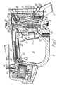
- an air pistol is shown as an application example for an electrical trigger device designed according to the invention, in which by actuating the trigger tongue 1 an electrical switch, designated in its entirety with 2 in FIG. 1, is closed, which is part of a circuit arrangement which is a arranged in the handle 3 of the gun battery 4, a capacitor 5 and a magnet 6, which receives a current surge when the switch 2 is closed by actuating the trigger 1 from the capacitor 5 charged by the battery 4, which causes the armature 7 one Lever 8 is actuated, the pivoting of which has the result that an extraction gallery 9 is made a catch on the air piston 10 of the pistol is disengaged, so that the air piston 10 can move forward under the action of the spring 11 loading it towards the barrel 12 and expel the air from the chamber 13 and press it into the barrel 12, such as it is generally known from air pressure weapons.
- the switch 2 which is shown enlarged in FIGS. 2 and 3 is located at the upper end of the handle 3 in the weapon housing 14 and borders on the rear of the space enclosed
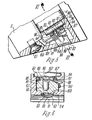
- the switch 2 consists essentially of two parts, namely a switch housing 21 and a contact lever 22.
- the switch housing 21 has a substantially U-shaped cross section, the transverse web of which forms the rear wall and the legs of which form side walls of the switch housing.
- the designations rear and side walls refer to the installation position of the switch housing in the gun, and in turn to the use position of the gun. Information on top and bottom as well as front and back are used accordingly.
- the contact lever 22 is arranged between the side walls of the switch housing and has near its upper end laterally protruding bearing pins 24 which engage in corresponding recesses 25 in the side walls of the switch housing 21 which form open bearing shells for the bearing pins 24.
- the contact lever 22 has a position just below the bearing journal 24 Recess with a web 26 on which a helical tension spring 27 is suspended, the other end of which is suspended on a transverse web 28, which is attached in a similar manner to the rear wall of the switch housing 21 as the transverse web 26 on the contact lever.
- the contact lever 22 is pulled by the tension spring 27 with its bearing pin 24 firmly into the recesses 25 serving as bearing shells and at the same time, since the point of application of the tension spring 27 is offset downwards relative to the pivot axis of the contact lever defined by the bearing pin, with its lower end 29 applied a stop of the switch housing, which is formed by a reinforced portion 30 of the rear wall of the switch housing.
- the contact lever 22 is slightly cranked in the region of its center, so that the front of its lower section 31 is substantially flush with the rear of its upper section 32.
- the contact lever 22 has an opening 33, through which a contact spring 34 extends, so that its lower section on the front of the lower section 31 of the contact lever and its upper section on the inside of the upper section 32 of the contact lever.
- a transverse web 35 is arranged just below the tension spring 27 on the rear side of the contact lever, the lower end of which rests on the upper end of the contact spring 34.
- the lower end of the contact spring 34 is located at a short distance fixed counter contact 36 opposite, which is attached to the rear of a wall portion 37, which connects the front edges of the side wall portions of the switch housing 21 in their lower region.
- the distance between the contact of the contact lever 22 formed by the contact spring 34 and the stationary counter contact 36 need only be a few hundredths of a millimeter.
- the contact lever 22 can be brought into contact with the mating contact 36 by exerting a rearward force on its upper end which projects beyond the bearing pins 25 and which is sufficient to overcome the force of the spring 27.
- the movement which the upper end of the contact lever 22 carries out is only a fraction of the distance between the contact spring 34 at the lower end 29 of the contact lever and the mating contact 36, since the pivot axis 26 defined by the bearing pin 25 is close to the upper end of the contact lever 22 is located and therefore the contact lever 22 forms a two-sided lever with arms of widely differing lengths.
- the switch 2 is fastened in the weapon housing 14 by a single screw 38 which is screwed into the reinforcement 30 at the lower end of the rear wall of the switch housing 21 and penetrates a lower wall section 39 of the weapon housing 14.
- the reinforcement 30 forms a protrusion beyond the lower edge of the switch housing 21, which engages in a corresponding recess in the housing wall 39, and the rear wall of the switch housing 21 is inclined slightly upwards outwards and is located on a correspondingly ge inclined counter surface of the gun case 14 attachment.
- the rear wall of the switch housing 21 is provided with an opening 4Q, with which an opening 41 in the wall of the weapon housing 14 is aligned.
- Lead wires 42, 43 are passed through these openings 40, 41, of which one lead wire 42 with the upper end of the contact spring 34 and the other lead wire 43 with a soldering tab 44 attached to the stationary mating contact 36, which passes past the contact lever 22 the inside of the switch housing 21 extends, is connected.
- the lead wires 42, 43 are connected in a manner not shown to the electrical circuitry inside the handle 3 of the air gun.
- the switch of the air gun shown can be closed by actuating the trigger tongue 1.
- the trigger tongue 1 is fastened by means of a holder 51 to a trigger rod 52, the upper half of the trigger guard 15 is arranged substantially horizontally and is mounted displaceably in its longitudinal direction.
- the trigger rod 52 engages with a projection 53 attached to its front end in the bore 54 of a fixed component of the weapon and is articulated at its rear end to the upper end of a link 55.
- the handlebar 55 has at the upper end a recess 56 into which the end of the trigger rod 52 engages and in the region of which the trigger rod 52 and the link 55 are connected to one another by a pin 57.
- the handlebar is pivotally mounted on a pin 58 in the weapon housing.
- the handlebar 55 extends essentially parallel to the switch and, with its upper end 59 projecting beyond the trigger rod 52, bears against the upper end 60 of the contact lever 22.
- the handlebar 55 has an axial threaded bore in its lower end, into which an adjusting screw 61 is screwed.
- the end of this set screw 61 lies against the angled arm 62 of a lever 63, which consists of a flat material, for example sheet steel.
- This lever has in its upper region an elongated recess 64, with which the lever engages over a shoulder attached to the rear of the handlebar 55 and on the lower edge of which the lever 63 rests with the lower edge of the recess 64, so that this edge is a bearing edge forms about which the lever 63 is pivotable.
- the set screw 69 is screwed into its drill hole to such an extent that the upper end 59 of the link 55 is almost in contact with the upper end 60 of the contact lever 22.
- the trigger mechanism of L u ftdruckpistole almost no stage travel on.
- the helical tension spring 67 determines the force required to move the trigger rod 52 by pivoting the handlebar 55 backwards by actuating the trigger tongue 1 until the upper end 59 of the handlebar comes into contact with the contact lever 60. That power can be changed using the adjusting screw 61. In the position illustrated in FIG. 2, the adjusting screw 61 is screwed in so far that the arm 62 of the lever 63 bears against the upper wall of the recess 65, so that the lever 63 cannot be pivoted further in the clockwise direction. The helical tension spring 67 has the greatest prestress, so that this position corresponds to the greatest trigger weight.
- the adjusting screw 61 If the adjusting screw 61 is unscrewed from the handlebar 55, it releases the arm 62 of the lever 63 increasingly, so that the lever 63 can perform a counterclockwise pivoting movement around the cutting edge which is formed by the lower edge of the recess 64. As a result, the upper end of the lever 63 moves forward, causing the coil spring 6? is increasingly relaxed. As a result, the trigger weight can be reduced in this way.
- the contact lever is carried along and pivoted as the trigger tongue moves further, so that the contact at the lower end of the contact lever 22 on the stationary counter contact 36 brought to the plant and thereby the switch is closed.
- the trigger device therefore has a clear pressure point, after which an increased effort is required.
- the additional passage that has to be traversed after reaching the pressure point is extremely small, and the trigger movement comes to rest against a stationary stop.
- the short pull-through distance after reaching the trigger in connection with the fixed stop for the pull-through movement is of the utmost importance for a perfect shot release.
- the shot is triggered after the switch formed by the contacts 34, 36 is closed by energizing the magnet 6.
- the circuit arrangement installed in the handle 3 of the air gun shown also comprises a battery test device with a test circuit containing a light-emitting diode and a switch connected in series with it.
- a base plate 81 is inserted into the lower end of the handle 3 and fastened to the handle by means of a screw 82 which has a bore 83 for receiving the cylindrical extension 84 of a push button 85.
- This push button 85 is made of a translucent material, in particular plastic, and has on the side opposite the neck 84 a substantially cylindrical recess 86, into which a light-emitting diode 87 is inserted such that the light-emitting surface faces the neck 84 and the connecting wires 88, 89 protrude from recess 86.
- the one connecting wire 88 is placed over the edge 90 delimiting the recess 86, which is followed by a recessed section 91, the contour of which follows the connecting wire 88.
- the other lead wire 89 is inserted into a radial groove 92, which is at the back of the print button 85 is located so that this lead wire 89 does not protrude beyond the back of the push button.
- a contact plate 93 is arranged in the base plate 81, closely adjacent to the rear side of the push button 85, the edges of which rest on strips 94, which delimit a recess 95 in the base plate 81 containing the push button 85 and on the outside of which faces away from the push button, webs 95 are connected , between which the contact plate 93 is fastened by caulking edge portions 96.
- an O-ring 97 Between the contact plate 93 and the adjacent surface of the push button 85 there is an O-ring 97, which both guides the push button 85 to a rear extension between the webs 94 and also supports the contact plate 93.
- the contact plate 93 and the O-ring 97 serve to hold the push button 85 securely in the base plate 81 in a position in which the connecting wire 88 placed over the edge 90 is at a distance from the contact plate 93.
- the connecting wire 88 and the contact plate 93 form a switch which is normally open and can be closed by pushing the push button 85 with elastic deformation of the O-ring 97 until the connecting wire 88 touches the contact plate 93.
- its end face 98 is set back relative to the outside of the base plate 81.
- the diameter of the bore 83 is only a few mm, it hardly seems possible to actuate the push button 85 with your finger without completely covering the bore 83, so that the opening then the light-emitting diode 87 can no longer be observed. Therefore, in the end face 98 of the push button there is a conical depression 100 in addition to a recess 99 aligned with the light-emitting diode 87, which allows a tool, for example a pencil tip, to be used to press in the push button 85.
- a lead wire 101 can be soldered to the end of the connecting wire 89 of the light emitting diode, which extends through the groove 92 without contact into the recess 95 of the base plate 81.
- the contact plate 93 is at the same time a battery contact and, for this purpose, has a bent-back section 102 which comes into contact with the bottom of the battery 4 inserted in the handle 3.
- the lead wire 101 can then, possibly via additional electrical components, be connected to the other battery pole, so that when the push button 85 is pressed, one of the connecting wires 88 via the contact plate 93 to one pole of the battery 4 and the other connecting wire 89 of the light-emitting diode is applied via line 101 to the other pole of the battery. No other connections are required for battery testing. However, it is also necessary to establish constant contact with the battery pole, against which the contact plate 93 rests, for feeding the electrical extraction device. A connecting wire 103 is therefore also connected to the contact plate 93.
- a trigger device according to the invention can be used with firearms of any kind, that is to say not only with air pressure pistols not only with air pressure rifles but also with firearms of any kind. With firearms, either a cocked firing member can be released or even one by closing the switch electrical ignition are triggered.
- the battery test device according to the invention can be used in all weapons where there is a need for such a test device.
- the preferred arrangement in the bottom of the handle is essentially only possible with air pistols, because there is hardly any space for the arrangement of the light emitting diode switch combination in the case of other weapons, although the arrangement of this combination in the bottom of the handle is particularly advantageous.
Landscapes
- Engineering & Computer Science (AREA)
- General Engineering & Computer Science (AREA)
- Mechanisms For Operating Contacts (AREA)
- Instructional Devices (AREA)
- Nozzles (AREA)
Applications Claiming Priority (2)
| Application Number | Priority Date | Filing Date | Title |
|---|---|---|---|
| DE3147886A DE3147886C2 (de) | 1981-12-03 | 1981-12-03 | Elektrische Abzugsvorrichtung für Schußwaffen |
| DE3147886 | 1981-12-03 |
Publications (2)
| Publication Number | Publication Date |
|---|---|
| EP0081130A2 true EP0081130A2 (fr) | 1983-06-15 |
| EP0081130A3 EP0081130A3 (fr) | 1984-04-11 |
Family
ID=6147812
Family Applications (1)
| Application Number | Title | Priority Date | Filing Date |
|---|---|---|---|
| EP82110745A Withdrawn EP0081130A3 (fr) | 1981-12-03 | 1982-11-20 | Système de détente électrique pour armes à feu |
Country Status (4)
| Country | Link |
|---|---|
| EP (1) | EP0081130A3 (fr) |
| DE (1) | DE3147886C2 (fr) |
| FI (1) | FI823991L (fr) |
| NO (1) | NO155262C (fr) |
Cited By (5)
| Publication number | Priority date | Publication date | Assignee | Title |
|---|---|---|---|---|
| EP0257169A1 (fr) * | 1986-08-12 | 1988-03-02 | Morini Competition Arm S.A. | Pistolet semi-automatique pour le tir sur cible |
| WO2012007617A1 (fr) | 2010-07-15 | 2012-01-19 | Gamo Outdoor, S.L. | Carabine à ressort avec actionneur |
| EP2619524B1 (fr) * | 2010-09-21 | 2018-12-26 | ATLAS ELEKTRONIK GmbH | Dispositif de fixation et ensembles et systèmes l'utilisant |
| CN109374065A (zh) * | 2018-12-07 | 2019-02-22 | 成都恒感科技有限公司 | 灌注桩施工用混凝土输料导管位置预警悬臂杠杆传感装置 |
| US20220333888A1 (en) * | 2021-04-19 | 2022-10-20 | Biofire Technologies Inc. | Electromechanical trigger and methods of operating a gun using the same |
Families Citing this family (2)
| Publication number | Priority date | Publication date | Assignee | Title |
|---|---|---|---|---|
| DE102007004587B4 (de) | 2007-01-30 | 2009-01-08 | Heckler & Koch Gmbh | Elektrische/mechanische Abzugseinrichtung |
| DE102016109695B4 (de) * | 2016-05-25 | 2018-04-12 | Carl Walther Gmbh | An einem Griff gelagerte Abzugs-Vorrichtung einer Kurz- oder Langwaffe |
Family Cites Families (4)
| Publication number | Priority date | Publication date | Assignee | Title |
|---|---|---|---|---|
| DE1553986B1 (de) * | 1967-05-24 | 1970-12-17 | Messerschmitt Boelkow Blohm | Elektromagnetischer Zuendgenerator |
| CH498358A (de) * | 1969-04-26 | 1970-10-31 | Messerschmitt Boelkow Blohm | Elektromagnetischer Zündgenerator |
| DE2404053A1 (de) * | 1974-01-29 | 1975-08-28 | Horst Wolff | Ausloese-, insbesondere zuendvorrichtung fuer waffen |
| DE2926559A1 (de) * | 1979-06-30 | 1981-01-22 | Walther Carl Gmbh | Elektrische abzugseinrichtung fuer schusswaffen |
-
1981
- 1981-12-03 DE DE3147886A patent/DE3147886C2/de not_active Expired
-
1982
- 1982-11-19 FI FI823991A patent/FI823991L/fi not_active Application Discontinuation
- 1982-11-20 EP EP82110745A patent/EP0081130A3/fr not_active Withdrawn
- 1982-12-02 NO NO824049A patent/NO155262C/no unknown
Cited By (9)
| Publication number | Priority date | Publication date | Assignee | Title |
|---|---|---|---|---|
| EP0257169A1 (fr) * | 1986-08-12 | 1988-03-02 | Morini Competition Arm S.A. | Pistolet semi-automatique pour le tir sur cible |
| WO2012007617A1 (fr) | 2010-07-15 | 2012-01-19 | Gamo Outdoor, S.L. | Carabine à ressort avec actionneur |
| US9074835B2 (en) | 2010-07-15 | 2015-07-07 | Gamo Outdoor, S.L. | Spring rifle with actuator |
| EP2619524B1 (fr) * | 2010-09-21 | 2018-12-26 | ATLAS ELEKTRONIK GmbH | Dispositif de fixation et ensembles et systèmes l'utilisant |
| CN109374065A (zh) * | 2018-12-07 | 2019-02-22 | 成都恒感科技有限公司 | 灌注桩施工用混凝土输料导管位置预警悬臂杠杆传感装置 |
| CN109374065B (zh) * | 2018-12-07 | 2024-02-23 | 成都恒感科技有限公司 | 灌注桩施工用混凝土输料导管位置预警悬臂杠杆传感装置 |
| US20220333888A1 (en) * | 2021-04-19 | 2022-10-20 | Biofire Technologies Inc. | Electromechanical trigger and methods of operating a gun using the same |
| US11555663B2 (en) * | 2021-04-19 | 2023-01-17 | Biofire Technologies Inc. | Electromechanical trigger and methods of operating a gun using the same |
| US12416462B2 (en) | 2021-04-19 | 2025-09-16 | Biofire Technologies Inc. | Electromechanical trigger and methods of operating a gun using the same |
Also Published As
| Publication number | Publication date |
|---|---|
| EP0081130A3 (fr) | 1984-04-11 |
| FI823991A7 (fi) | 1983-06-04 |
| NO155262C (no) | 1987-03-04 |
| NO824049L (no) | 1983-06-06 |
| FI823991A0 (fi) | 1982-11-19 |
| FI823991L (fi) | 1983-06-04 |
| NO155262B (no) | 1986-11-24 |
| DE3147886C2 (de) | 1985-06-13 |
| DE3147886A1 (de) | 1983-06-23 |
Similar Documents
| Publication | Publication Date | Title |
|---|---|---|
| AT402348B (de) | Laser-zielgerät für handfeuerwaffen | |
| DE102012019911B4 (de) | Magazinlöse-/-haltevorrichtung einer Feuerwaffe und mit dieser jeweils ausgestattetes Griffstück und Waffengehäuse einer Feuerwaffe | |
| AT410140B (de) | Sicherungsvorrichtung für jagd- und sportwaffen | |
| DE2927099A1 (de) | Elektrische ausloesevorrichtung fuer schusswaffen | |
| EP1830152B1 (fr) | Chargeur enfichable pour arme à feu | |
| DE1563788C3 (de) | Handbetätigtes Stellglied zur stufenlosen Drehzahlsteuerung eines Elektrowerkzeuges | |
| DE3505443C2 (fr) | ||
| CH685262A5 (de) | Mit Spannabzug oder selbstspannende Feuerwaffe. | |
| DE102016109695B4 (de) | An einem Griff gelagerte Abzugs-Vorrichtung einer Kurz- oder Langwaffe | |
| EP0081130A2 (fr) | Système de détente électrique pour armes à feu | |
| EP2966397B1 (fr) | Fusil à emprunt de gaz | |
| EP0437736B1 (fr) | Module de culasse démontable pour fusil | |
| CH650618A5 (de) | Drucktaste mit impuls- oder rastfunktion. | |
| DE3021598C2 (de) | Drucktastenschalter | |
| DE1553868C3 (de) | Elektronisch gesteuerte Abzugseinrichtung für Handfeuerwaffen | |
| DE2330430A1 (de) | Handfeuerwaffe fuer zweihandbedienung | |
| DE29715238U1 (de) | Vorrichtung zur Zündung einer Patrone | |
| EP0437739A2 (fr) | Extracteur de cartouches | |
| AT395909B (de) | Pistole | |
| EP1597530B1 (fr) | Systeme de detente pour armes a feu de poing | |
| DE7811175U1 (de) | Rasteinrichtung für einen Drucktastenschalter | |
| DE605392C (de) | Schalter mit geradlinig bewegtem Schaltorgan fuer das Schalten mehrerer Stromkreise in einer vorbestimmten Reihenfolge | |
| DE1578472A1 (de) | Sicherheits- und Zuendeinrichtung fuer Geschosse | |
| DE7903379U1 (de) | Drucktastenschalter | |
| DE3126291C2 (de) | Schnellfeuergewehr |
Legal Events
| Date | Code | Title | Description |
|---|---|---|---|
| PUAI | Public reference made under article 153(3) epc to a published international application that has entered the european phase |
Free format text: ORIGINAL CODE: 0009012 |
|
| AK | Designated contracting states |
Designated state(s): AT CH FR LI SE |
|
| PUAL | Search report despatched |
Free format text: ORIGINAL CODE: 0009013 |
|
| AK | Designated contracting states |
Designated state(s): AT CH FR LI SE |
|
| STAA | Information on the status of an ep patent application or granted ep patent |
Free format text: STATUS: THE APPLICATION IS DEEMED TO BE WITHDRAWN |
|
| 18D | Application deemed to be withdrawn |
Effective date: 19850411 |
|
| RIN1 | Information on inventor provided before grant (corrected) |
Inventor name: WOEHRSTEIN, EDWIN |