EP0081267A2 - Apparat zur Kontaktierung von Feststoffpartikeln mit Fluiden - Google Patents
Apparat zur Kontaktierung von Feststoffpartikeln mit Fluiden Download PDFInfo
- Publication number
- EP0081267A2 EP0081267A2 EP82201532A EP82201532A EP0081267A2 EP 0081267 A2 EP0081267 A2 EP 0081267A2 EP 82201532 A EP82201532 A EP 82201532A EP 82201532 A EP82201532 A EP 82201532A EP 0081267 A2 EP0081267 A2 EP 0081267A2
- Authority
- EP
- European Patent Office
- Prior art keywords
- column
- deflecting means
- solid material
- fluid
- particulate solid
- Prior art date
- Legal status (The legal status is an assumption and is not a legal conclusion. Google has not performed a legal analysis and makes no representation as to the accuracy of the status listed.)
- Withdrawn
Links
- 239000012530 fluid Substances 0.000 title claims abstract description 35
- 239000011343 solid material Substances 0.000 title claims abstract description 32
- 239000003054 catalyst Substances 0.000 description 17
- 239000007788 liquid Substances 0.000 description 13
- 239000007787 solid Substances 0.000 description 5
- 239000002245 particle Substances 0.000 description 4
- 239000011949 solid catalyst Substances 0.000 description 4
- 230000003197 catalytic effect Effects 0.000 description 3
- 238000010791 quenching Methods 0.000 description 3
- 230000000171 quenching effect Effects 0.000 description 3
- 238000009826 distribution Methods 0.000 description 2
- 238000006243 chemical reaction Methods 0.000 description 1
- 238000011109 contamination Methods 0.000 description 1
- 238000001816 cooling Methods 0.000 description 1
- 230000000694 effects Effects 0.000 description 1
- 238000005429 filling process Methods 0.000 description 1
- 230000014759 maintenance of location Effects 0.000 description 1
- 239000007769 metal material Substances 0.000 description 1
- 239000000203 mixture Substances 0.000 description 1
- 239000003208 petroleum Substances 0.000 description 1
- 239000011819 refractory material Substances 0.000 description 1
- 230000000979 retarding effect Effects 0.000 description 1
- 238000003892 spreading Methods 0.000 description 1
- 239000000126 substance Substances 0.000 description 1
- 210000004233 talus Anatomy 0.000 description 1
- 238000003466 welding Methods 0.000 description 1
Images
Classifications
-
- B—PERFORMING OPERATIONS; TRANSPORTING
- B01—PHYSICAL OR CHEMICAL PROCESSES OR APPARATUS IN GENERAL
- B01J—CHEMICAL OR PHYSICAL PROCESSES, e.g. CATALYSIS OR COLLOID CHEMISTRY; THEIR RELEVANT APPARATUS
- B01J8/00—Chemical or physical processes in general, conducted in the presence of fluids and solid particles; Apparatus for such processes
- B01J8/08—Chemical or physical processes in general, conducted in the presence of fluids and solid particles; Apparatus for such processes with moving particles
- B01J8/12—Chemical or physical processes in general, conducted in the presence of fluids and solid particles; Apparatus for such processes with moving particles moved by gravity in a downward flow
-
- B—PERFORMING OPERATIONS; TRANSPORTING
- B01—PHYSICAL OR CHEMICAL PROCESSES OR APPARATUS IN GENERAL
- B01J—CHEMICAL OR PHYSICAL PROCESSES, e.g. CATALYSIS OR COLLOID CHEMISTRY; THEIR RELEVANT APPARATUS
- B01J8/00—Chemical or physical processes in general, conducted in the presence of fluids and solid particles; Apparatus for such processes
- B01J8/08—Chemical or physical processes in general, conducted in the presence of fluids and solid particles; Apparatus for such processes with moving particles
- B01J8/12—Chemical or physical processes in general, conducted in the presence of fluids and solid particles; Apparatus for such processes with moving particles moved by gravity in a downward flow
- B01J8/125—Chemical or physical processes in general, conducted in the presence of fluids and solid particles; Apparatus for such processes with moving particles moved by gravity in a downward flow with multiple sections one above the other separated by distribution aids, e.g. reaction and regeneration sections
-
- B—PERFORMING OPERATIONS; TRANSPORTING
- B01—PHYSICAL OR CHEMICAL PROCESSES OR APPARATUS IN GENERAL
- B01J—CHEMICAL OR PHYSICAL PROCESSES, e.g. CATALYSIS OR COLLOID CHEMISTRY; THEIR RELEVANT APPARATUS
- B01J2208/00—Processes carried out in the presence of solid particles; Reactors therefor
- B01J2208/00796—Details of the reactor or of the particulate material
- B01J2208/00823—Mixing elements
- B01J2208/00831—Stationary elements
- B01J2208/0084—Stationary elements inside the bed, e.g. baffles
Definitions
- the invention relates to an apparatus for contacting particulate solid material with a fluid, said apparatus comprising a column provided with an inlet for particulate solid material at its upper part, an outlet for the particulate solid material at its lower part, an inlet for fluid and an outlet for the fluid, the interior of the column being provided with a plurality of deflecting means for deflecting a flow of the particulate solid material through the column, the deflecting means being arranged one above the other and being inclined with respect to a vertical plane, adjacent deflecting means being staggered relative to one another.
- particulate solid material is cascaded downwardly through the column, and is thereby intensively contacted with fluid which is co-currently or countercurrently passed through the column.
- Columns of this type are used, for instance, for absorbing components from fluid mixtures, for the chemical conversion of fluids by solid catalysts and for the removal of absorbed volatile components from solid particles.
- the deflecting means in such known columns regulate the flow of particulate solid material to effect an intensive contact with the fluid while simultaneously retarding this flow for a period sufficient to provide a retention time necessary for a specified efficiency of operation.
- Columns are known wherein the deflecting means are alternately arranged on either side of the axis of the column, leaving passages for solids and fluid between the lower ends of said deflecting means and the column wall.
- the deflecting means impart a zig-zag movement to the solid material, thereby creating an intensive contact between the solid material and fluid and a spreading of the solid material over the column.
- a disadvantage of columns provided with the known deflecting means is that the available space in the columns can only be partly used for the contact of solid material with fluid.
- An object of the present invention is to provide an apparatus of the above-mentioned type having such an arrangement of the deflecting means that substantially the whole available space in the column can be used for the fluid/solids contact.
- the apparatus for contacting particulate solid material with a fluid comprises, according to the invention, a column having a normally vertically extending side wall and provided with an inlet for particulate solid material at its upper part, an outlet for the particulate solid material at its lower part, an inlet for fluid and an outlet for the fluid, the interior of the column being provided with a plurality of deflecting means for deflecting a flow of the particulate solid material through the column, the deflecting means being arranged one above the other and being inclined with respect to a vertical plane, adjacent deflecting means being staggered relative to one another, wherein passages are left free between the upper ends of the deflecting means and the side wall of the column and between the lower ends of the deflecting means and the side wall of the column.
- the particulate solid material and fluid can reach all spaces in the column, so that an efficient use of the column is ensured.
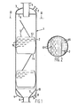
- the column shown in Figure 1 and generally indicated by reference numeral 1 is formed of a tubular side wall 2, a curved top wall 3 and a curved bottom wall 4.
- the column which may, for example, be applied for the catalytic treatment of fluids further comprises a central inlet 5 in the top wall 3 and a central outlet 6 in the bottom wall 4 for particulate solid material.
- Fluid is introduced via an inlet 7 and discharged from the column via an outlet 8.
- the column 1 further comprises a perforated tray 9 for distributing the fluid over the column, said tray being arranged around the central inlet 5.
- a conically shaped support 10 is arranged for guiding the solids in the column towards the central outlet 6.
- the conical support 10 is provided with a screen section 11 being impermeable to particulate solid material and permeable to fluid.
- the interior of the column is further provided with downwardly inclined baffles 12, being so arranged relative to each other that there is no straight free passage from the top to the bottom of the column 1.
- the baffles 12 are preferably turned over 90°C with respect to adjacent ones in such a manner that the odd and even numbers of the baffles 12 are turned over 180°C with respect to each other.
- the baffles 12 each have a straight upper end 13 and a straight lower end 14, thereby leaving free passages for solid material and fluid between the upper end 13 and the column wall 2 and between the lower end 14 and the column wall 2.
- the baffles 12 are further provided with horizontal slit-shaped openings 15 for distributing fluid over the column interior.
- the angle of inclination of the baffles 12 should preferably correspond with the angle of repose of the solid material, i.e., the angle between the horizontal and the inclined talus of the solid material piled in the column.
- the liquid upon flowing downwardly through the column 1 is intensively contacted with the catalyst in the column 1 so that certain contaminations in the liquid are removed therefrom and are absorbed by the catalyst particles or adhere to the catalyst surfaces.
- the slit-shaped openings 15 in the baffles 12 ensure a redistribution of the liquid over the column, so that no preferential liquid flow paths extending over a substantial length of the column are formed.
- the treated liquid is subsequently discharged from the column 1 via the screen 11 and the fluid outlet 8.
- the slit-shaped openings 15 in each baffle are preferably arranged in rows, each row being staggered relative to an adjacent row.
- Catalyst is continuously or intermittently withdrawn from the column 1 via the central outlet 6.
- the baffles 12 cause an intensive internal mixing of the catalyst particles.
- eventual hot spots between two adjacent baffles 12 in the catalyst bed which might have been formed during the liquid treatment are cooled by catalyst particles which were hardly not contacted with the liquid.
- Further preferential liquid flow pathes formed in the catalyst bed between adjacent baffles 12 during the liquid treatment are removed by the catalyst flow and the catalyst is equally redistributed over the column.
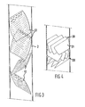
- FIG. 4 showing a part of a column provided with an alternative of the deflecting means shown in Figure 1, in particular useful for relatively largesized columns.
- the deflecting means 20 shown in Figure 4 each consist of a plurality of substantially parallel, inclined, baffles 21 spaced apart from each other. Between the upper end of each baffle 21 and the column wall a passage for fluid and solids is arranged, as well as between the lower end of each baffle 21 and the column wall.
- the distance between adjacent baffles 21 should be sufficient to allow solid material to pass downwardly between said adjacent baffles.
- the operation of the deflecting means shown in Figure 4 is identical to the operation of the deflecting means shown in the Figures 1 and 2.
- the baffles shown in Figures 1 through 3 may be formed of refractory or metallic materials, and they are supported on the inner surface of the column wall, for example, by welding the baffles to said column wall or by means of supporting rings.
- the column may also be of the so-called countercurrent type without departing from the present invention.
- the inlet for fluid is arranged at the lower part of the column and the outlet for fluid is arranged at the upper part of the column.
- Such type of column may for example be used for stripping catalyst withdrawn from a column shown in Figure 1.
- baffles shown in the drawings are flat-shaped, it is noted that also baffles being slightly curved may be applied.
- redistribution of liquid over the column cross section is obtained by the passages between adjacent parallel baffles. It will be understood that these baffles may be further provided with openings as shown in Figure 1 to obtain a further redistribution of the fluid treated in the column.
- any 5 other shape of openings can be applied, such as a circular shape.
- the openings are preferably equally distributed over the baffle surface.
- the openings in adjacent baffles 12 should be in a staggered position relative to one another. It should be noted that in small-sized columns the openings in the baffles are not strictly necessary.
- the baffles may be provided with quenching means for cooling the interior of the column.
- the quenching means may suitably be arranged at the lower surfaces of the baffles. Preferably the quenching means if applied are equally distributed over the baffle surfaces.
Landscapes
- Chemical & Material Sciences (AREA)
- Organic Chemistry (AREA)
- Chemical Kinetics & Catalysis (AREA)
- Devices And Processes Conducted In The Presence Of Fluids And Solid Particles (AREA)
Applications Claiming Priority (2)
| Application Number | Priority Date | Filing Date | Title |
|---|---|---|---|
| GB08136506A GB2110560A (en) | 1981-12-03 | 1981-12-03 | Apparatus for contacting particulate solid material with a fluid |
| GB8136506 | 1981-12-03 |
Publications (2)
| Publication Number | Publication Date |
|---|---|
| EP0081267A2 true EP0081267A2 (de) | 1983-06-15 |
| EP0081267A3 EP0081267A3 (de) | 1983-10-19 |
Family
ID=10526356
Family Applications (1)
| Application Number | Title | Priority Date | Filing Date |
|---|---|---|---|
| EP82201532A Withdrawn EP0081267A3 (de) | 1981-12-03 | 1982-12-01 | Apparat zur Kontaktierung von Feststoffpartikeln mit Fluiden |
Country Status (5)
| Country | Link |
|---|---|
| EP (1) | EP0081267A3 (de) |
| JP (1) | JPS58122035A (de) |
| AU (1) | AU9072082A (de) |
| BR (1) | BR8206941A (de) |
| GB (1) | GB2110560A (de) |
Cited By (1)
| Publication number | Priority date | Publication date | Assignee | Title |
|---|---|---|---|---|
| WO2004047975A1 (en) * | 2002-11-25 | 2004-06-10 | Abb Lummus Global Inc. | Apparatus for countercurrent contacting of gas and solids |
Families Citing this family (1)
| Publication number | Priority date | Publication date | Assignee | Title |
|---|---|---|---|---|
| CN102755866A (zh) * | 2012-07-02 | 2012-10-31 | 魏治中 | 一种多层格栅叠加的汽提器 |
Family Cites Families (6)
| Publication number | Priority date | Publication date | Assignee | Title |
|---|---|---|---|---|
| GB686077A (en) * | 1949-07-01 | 1953-01-14 | Heurtey & Cie | Improvements in or relating to the treatment of pulverulent substances with gases |
| GB1000553A (en) * | 1960-08-04 | 1965-08-04 | Richardsons Westgarth & Co | Improvements in or relating to apparatus for carrying out heterogenous-reactions |
| US3409411A (en) * | 1965-07-26 | 1968-11-05 | Exxon Research Engineering Co | Apparatus for separating solids and loading reactor vessel |
| CA1015135A (en) * | 1974-02-22 | 1977-08-09 | Richard D. Warda | Method and apparatus for treating particulate material |
| GB2034196B (en) * | 1978-11-07 | 1983-05-18 | Atomic Energy Authority Uk | Contacting particulate solids with liquids |
| CH642272A5 (de) * | 1979-07-10 | 1984-04-13 | Escher Wyss Ag | Einrichtung zur mechanischen, thermischen oder chemischen behandlung eines fliessfaehigen stoffes mit einem fluid. |
-
1981
- 1981-12-03 GB GB08136506A patent/GB2110560A/en not_active Withdrawn
-
1982
- 1982-11-19 AU AU90720/82A patent/AU9072082A/en not_active Abandoned
- 1982-11-30 BR BR8206941A patent/BR8206941A/pt unknown
- 1982-12-01 EP EP82201532A patent/EP0081267A3/de not_active Withdrawn
- 1982-12-02 JP JP21205782A patent/JPS58122035A/ja active Pending
Cited By (4)
| Publication number | Priority date | Publication date | Assignee | Title |
|---|---|---|---|---|
| WO2004047975A1 (en) * | 2002-11-25 | 2004-06-10 | Abb Lummus Global Inc. | Apparatus for countercurrent contacting of gas and solids |
| US7179427B2 (en) | 2002-11-25 | 2007-02-20 | Abb Lummus Global Inc. | Apparatus for countercurrent contacting of gas and solids |
| AU2003291082B2 (en) * | 2002-11-25 | 2009-06-25 | Lummus Technology Inc. | Apparatus for countercurrent contacting of gas and solids |
| CN100540131C (zh) * | 2002-11-25 | 2009-09-16 | Abb路慕斯全球股份有限公司 | 用于气体和固体的逆流接触的设备 |
Also Published As
| Publication number | Publication date |
|---|---|
| JPS58122035A (ja) | 1983-07-20 |
| BR8206941A (pt) | 1983-10-04 |
| EP0081267A3 (de) | 1983-10-19 |
| GB2110560A (en) | 1983-06-22 |
| AU9072082A (en) | 1983-06-09 |
Similar Documents
| Publication | Publication Date | Title |
|---|---|---|
| JP3774253B2 (ja) | 複合ベッド下降流反応器用分布装置 | |
| US7070745B2 (en) | Multiple bed downflow reactor | |
| US5554346A (en) | Fluids mixing and distributing apparatus | |
| JP3365636B2 (ja) | 多床下降流触媒反応器のための分配器組立体 | |
| JP2002512108A (ja) | 並流接触分離段の設計およびその使用方法 | |
| US5291989A (en) | Catalyst system for distillation reactor | |
| JP2004512924A (ja) | 効率増強分留トレイ及びプロセス | |
| EP0364117B1 (de) | Verfahren zum Vermischen von Dämpfen in einer Gegenstrom-Kolonne | |
| US5496446A (en) | Internals for distillation columns including those for use in catalytic reactions | |
| JPH02503291A (ja) | 移動層反応装置及びその運転方法 | |
| US5855741A (en) | Apparatus for concurrent reaction with distillation | |
| EP0081267A2 (de) | Apparat zur Kontaktierung von Feststoffpartikeln mit Fluiden | |
| US6126905A (en) | Baffles for a fluid to fluid contactor | |
| US3143581A (en) | Liquid distributing apparatus | |
| EP0207673A1 (de) | Flüssigkeitsverteiler und seine Verwendung | |
| JPH06312126A (ja) | 気液接触装置 | |
| EP0888156B1 (de) | Verfahren und vorrichtung zur reaktivdestillation | |
| US2548285A (en) | Method and apparatus for hydrocarbon conversion | |
| JPH07222921A (ja) | 液体の集合方法及び集合板と、液体の集合分配方法及び集合分配機構と、液体の気液又は液液接触方法及び液体の気液又は液液接触機構と、液体の気液又は液液接触集合分配機構と、それらの機構を含む装置 | |
| EP0664721B1 (de) | Verfahren und apparat für die gleichzeitige reaktion und distillation | |
| KR830000403B1 (ko) | 이동층(移動層) 방사상유동 고체-유체 접촉장치 | |
| CN87103951A (zh) | 用于立式流动的流体固体接触的混合装置 | |
| CZ283443B6 (cs) | Zariadenie na redistribúciu kvapaliny v náplňových kolónach |
Legal Events
| Date | Code | Title | Description |
|---|---|---|---|
| PUAI | Public reference made under article 153(3) epc to a published international application that has entered the european phase |
Free format text: ORIGINAL CODE: 0009012 |
|
| 17P | Request for examination filed |
Effective date: 19821201 |
|
| AK | Designated contracting states |
Designated state(s): BE DE FR IT NL SE |
|
| PUAL | Search report despatched |
Free format text: ORIGINAL CODE: 0009013 |
|
| AK | Designated contracting states |
Designated state(s): BE DE FR IT NL SE |
|
| STAA | Information on the status of an ep patent application or granted ep patent |
Free format text: STATUS: THE APPLICATION HAS BEEN WITHDRAWN |
|
| 18W | Application withdrawn |
Withdrawal date: 19841106 |
|
| RIN1 | Information on inventor provided before grant (corrected) |
Inventor name: VAN VELDHOVEN, DIRK JAN |