EP0081401A1 - System zur zeitweiligen Festlegung und Freigabe zweier Teile, insbesondere in der Raumfahrttechnik - Google Patents
System zur zeitweiligen Festlegung und Freigabe zweier Teile, insbesondere in der Raumfahrttechnik Download PDFInfo
- Publication number
- EP0081401A1 EP0081401A1 EP82402002A EP82402002A EP0081401A1 EP 0081401 A1 EP0081401 A1 EP 0081401A1 EP 82402002 A EP82402002 A EP 82402002A EP 82402002 A EP82402002 A EP 82402002A EP 0081401 A1 EP0081401 A1 EP 0081401A1
- Authority
- EP
- European Patent Office
- Prior art keywords
- mobile
- link
- support
- stacking
- stirrup
- Prior art date
- Legal status (The legal status is an assumption and is not a legal conclusion. Google has not performed a legal analysis and makes no representation as to the accuracy of the status listed.)
- Granted
Links
Images



Classifications
-
- B—PERFORMING OPERATIONS; TRANSPORTING
- B64—AIRCRAFT; AVIATION; COSMONAUTICS
- B64G—COSMONAUTICS; VEHICLES OR EQUIPMENT THEREFOR
- B64G1/00—Cosmonautic vehicles
- B64G1/22—Parts of, or equipment specially adapted for fitting in or to, cosmonautic vehicles
- B64G1/222—Parts of, or equipment specially adapted for fitting in or to, cosmonautic vehicles for deploying structures between a stowed and deployed state
- B64G1/2228—Parts of, or equipment specially adapted for fitting in or to, cosmonautic vehicles for deploying structures between a stowed and deployed state characterised by the hold-down or release mechanisms
-
- B—PERFORMING OPERATIONS; TRANSPORTING
- B64—AIRCRAFT; AVIATION; COSMONAUTICS
- B64G—COSMONAUTICS; VEHICLES OR EQUIPMENT THEREFOR
- B64G1/00—Cosmonautic vehicles
- B64G1/22—Parts of, or equipment specially adapted for fitting in or to, cosmonautic vehicles
- B64G1/64—Systems for coupling or separating cosmonautic vehicles or parts thereof, e.g. docking arrangements
- B64G1/645—Separators
- B64G1/6455—Pyrotechnics; Using heat
-
- B—PERFORMING OPERATIONS; TRANSPORTING
- B64—AIRCRAFT; AVIATION; COSMONAUTICS
- B64G—COSMONAUTICS; VEHICLES OR EQUIPMENT THEREFOR
- B64G1/00—Cosmonautic vehicles
- B64G1/22—Parts of, or equipment specially adapted for fitting in or to, cosmonautic vehicles
- B64G1/42—Arrangements or adaptations of power supply systems
- B64G1/44—Arrangements or adaptations of power supply systems using radiation, e.g. deployable solar arrays
-
- Y—GENERAL TAGGING OF NEW TECHNOLOGICAL DEVELOPMENTS; GENERAL TAGGING OF CROSS-SECTIONAL TECHNOLOGIES SPANNING OVER SEVERAL SECTIONS OF THE IPC; TECHNICAL SUBJECTS COVERED BY FORMER USPC CROSS-REFERENCE ART COLLECTIONS [XRACs] AND DIGESTS
- Y10—TECHNICAL SUBJECTS COVERED BY FORMER USPC
- Y10S—TECHNICAL SUBJECTS COVERED BY FORMER USPC CROSS-REFERENCE ART COLLECTIONS [XRACs] AND DIGESTS
- Y10S343/00—Communications: radio wave antennas
- Y10S343/02—Satellite-mounted antenna
-
- Y—GENERAL TAGGING OF NEW TECHNOLOGICAL DEVELOPMENTS; GENERAL TAGGING OF CROSS-SECTIONAL TECHNOLOGIES SPANNING OVER SEVERAL SECTIONS OF THE IPC; TECHNICAL SUBJECTS COVERED BY FORMER USPC CROSS-REFERENCE ART COLLECTIONS [XRACs] AND DIGESTS
- Y10—TECHNICAL SUBJECTS COVERED BY FORMER USPC
- Y10T—TECHNICAL SUBJECTS COVERED BY FORMER US CLASSIFICATION
- Y10T24/00—Buckles, buttons, clasps, etc.
- Y10T24/44—Clasp, clip, support-clamp, or required component thereof
- Y10T24/44291—Clasp, clip, support-clamp, or required component thereof including pivoted gripping member
- Y10T24/44376—Spring or resiliently biased about pivot
- Y10T24/44385—Distinct spring
- Y10T24/44427—Distinct spring with position locking-means for gripping members
- Y10T24/44436—Distinct spring with position locking-means for gripping members including pivoted arm
Definitions
- the present invention relates to a holding and release system for ensuring a temporary connection between two parts which must be separated from each other during their own use.
- the link must temporarily ensure the positioning and the transmission of the forces of the supported part during the various phases of bringing the vehicle into operational configuration, such as for example during the phase of vehicle launch or appendix deployment phase; the release must allow the supported part which has been released to oscillate in relation to the position where it has been maintained.
- the pointing device By the rotation around two orthogonal axes, the pointing device ensures the orientation of the mobile carrying part of the antenna in order to provide the required coverage.
- the system for temporarily holding and releasing a movable part relative to a fixed part is characterized in that it comprises a certain number of elementary devices, each of which consists of: a support leg linked to the fixed part; a rod forming a pendulum articulated in its middle part on said foot; an element forming a mobile support articulated at one of the ends of the link; a stacking stirrup articulated on the other end of the link; the rod being capable of occupying either a locking position in which the movable support comes to bear on one face of the movable part, while the free end of the stacking stirrup comes to bear on the other face of the part mobile, opposite the mobile support, which causes the mobile part to immobilize in a very precise position, that is to say a release position in which the mobile support and the stacking stirrup are located, one and the other, in an erasing position, which frees the movable part from any holding constraint and allows it to oscillate; a trigger articulated on said foot having the
- the present invention relates to a device with the dual role of temporary immobilization and of release of a carrying mobile part with respect to a fixed part of the vehicle.
- the holding and release device consists essentially of: a foot 1 fixed by any suitable means on the appropriate part 2 of the satellite so that the device can participate in the immobilization of a mobile part 3 in a well-determined position during the different phases of the satellite setting :; a link 4 articulated in its middle part, on a transverse axis 5 of the foot 1; this rod acting as a pendulum; a mobile support 6 articulated at one end of the link 5 on a transverse axis 7; a stacking stirrup C-shaped, 8, articulated at its lower end (in the drawing) on an axis 9 fixed to the second end of the link 4.
- the link 4 can occupy two possible positions which are shown, respectively , in FIG. 1 which is the stacked or immobilized configuration of the mobile part 3 in its average position corresponding to the missile launching phase and in FIG. 2 which is the released configuration in which the mobile part 3 is free to oscillate in the direction F 1 or the direction F 2 around the mean launch position of FIG. 1.
- the rod 4, in the launch configuration is held in a substantially vertical position (in the drawing) using a trigger 11 itself immobilized in this locking position by a stacking cable 12 ( Figure 3) to which we will return in detail later.
- the trigger 11, which is articulated on a vertical axis 13 secured to the foot 1 is provided with a head 11A coming to bear on a shoulder 4A of the link 4.
- the mobile support 6 articulated on the link 4 is immobilized in a vertical position, against the foot 1 in a V-shaped housing 10 which is provided with said foot, by means of the link 4 it even blocked by the trigger 11.
- the mobile support 6 has a cross section complementary to that of the housing 10 of the foot 1.
- the stacking stirrup 8 in the form of a C ensures the effort of maintaining the movable part 3 on the movable support 6.
- the upper end 8A of the lever 8 is provided a tensioning screw 14 coming to bear on the upper face of the movable element 3. This screw makes it possible to obtain the required clamping force.
- the control of this tension can advantageously be carried out by strain gauges glued to the stirrup and previously calibrated in the range of force to be applied.
- the geometric axis, that of the axis 9 on which the foot of the stirrup 8 is articulated is contained in a plane P 1 offset by an interval Edu vertical plane P 2 in which are contained the geometric axes of the articulation axis 5 of the link 4 and of the articulation axis 7 of the movable support 6.
- stirrup 8 is held on a path imposed by a slot 15 which it is provided with, sliding against a fixed guide pin 16.
- a return spring 17 fixed between the link 4 and a fixed point 18 ensures complete erasure as well as immobilization both of the link 4 and of the stirrup 8 to ensure them in the relative positions of the release configuration. in Figure 2.
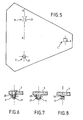
- FIG. 4 shows the possible triangular distribution on a fixed element 2 of three holding devices designated by the general references A, B and C of the mobile part (not shown).
- each of the devices A, B and C is shown diagrammatically by its movable support 6, in the high position, the V-shaped part forming a stop 10 of its foot and its release trigger 11.
- the V-shaped part forming a stop 10 of its foot and its release trigger 11.
- return pulleys 24 and 25 ensure perfect orientation of the cable 12 to keep the triggers 11 in the locked position.
- the major advantage of the present invention lies in the fact that the immobilization of the movable part 3 takes place in a precise mean position, which makes it possible to eliminate any constraint on the orientation mechanisms of said movable part in position satellite operational.
- the mobile carrying part of the antenna can be linked to the fixed part 2 of the satellite by a securing device, for example mechanical, and consisting of a thin cylinder of an openwork elastic material along its front face of concentric openings in alternating sectors, this cylinder being shown diagrammatically in 2A in FIG. 4.
- a securing device for example mechanical, and consisting of a thin cylinder of an openwork elastic material along its front face of concentric openings in alternating sectors, this cylinder being shown diagrammatically in 2A in FIG. 4.
- the invention also has other advantages, in particular with regard to the transmission of forces during the launch phase, which constitutes an important problem to be solved.
- This solution has the advantage of ensuring the passage of forces in the horizontal plane (on the drawing) as well as the precise repositioning at each stacking.
- the mobile part 3 and the mobile support 6 have a rough surface formed by pyramid-shaped points 31 for the first and 32 for the second, the contact between these two rough surfaces being obtained by an intermediate metallic shim 33 whose malleability is determined on request.
- the clamping force of the stirrup depends on the friction coefficient determined by test.
- the bracket 8 behaves like a spring, which guarantees a minimum clamping force essential for the transmission of forces in the horizontal plane.
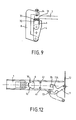
- the essential characteristic of the variant embodiment of FIGS. 10 to 12 resides in the arrangement, between the link 4 and the trigger 11, of a mechanical relay bearing the general reference 34 which has the effect of ensuring a reduction gear conducive to the limitation of the loads induced in the stacking cable 12.
- FIGS. 10 to 12 consists essentially of: a locking lever 35 in the form of a square, articulated at its upper free end on an axis 36 integral, with a shoulder 1A of the foot 1 and the lower free end of which serves as a support for the shoulder 11A of the trigger 11 in the stacking position; a connecting bar 37 articulated, at one of its ends, on an axis 38 integral with the end shoulder 4A of the rod 4 and at its other end on an axis 39 arranged in the corner right of the locking lever 35; and a stop screw 40 mounted on the shoulder 1A of the foot 1 and which comes to bear (see FIG.
- this stop screw 40 for adjusting the reversibility of the system, by changing the distance from the geometric axis of the hinge pin 39 to the virtual line connecting the geometric axes of the extreme articulation axes 36 and 38.
- the return spring 17 which was fixed between a point 18 of the fixed part 2 and a point on the free end of the link 4, in the embodiment of Figures 1 and 2, is here fixed between a point 18 of the fixed part 2 and a point on the lower free end of the locking lever 35.
- a stop 41 can advantageously be provided to immobilize the mobile support 6 in a perfectly defined position in the deployed configuration of FIG. 11.
Landscapes
- Engineering & Computer Science (AREA)
- Remote Sensing (AREA)
- Aviation & Aerospace Engineering (AREA)
- Details Of Aerials (AREA)
- Automobile Manufacture Line, Endless Track Vehicle, Trailer (AREA)
- Pivots And Pivotal Connections (AREA)
- Mechanical Control Devices (AREA)
- Vehicle Step Arrangements And Article Storage (AREA)
- Hinges (AREA)
- Aerials With Secondary Devices (AREA)
- Electrical Discharge Machining, Electrochemical Machining, And Combined Machining (AREA)
Priority Applications (1)
| Application Number | Priority Date | Filing Date | Title |
|---|---|---|---|
| AT82402002T ATE25952T1 (de) | 1981-11-26 | 1982-10-28 | System zur zeitweiligen festlegung und freigabe zweier teile, insbesondere in der raumfahrttechnik. |
Applications Claiming Priority (2)
| Application Number | Priority Date | Filing Date | Title |
|---|---|---|---|
| FR8122144 | 1981-11-26 | ||
| FR8122144A FR2516893A1 (fr) | 1981-11-26 | 1981-11-26 | Systeme permettant le maintien temporaire et la liberation de deux parties, plus particulierement dans le domaine spatial |
Publications (2)
| Publication Number | Publication Date |
|---|---|
| EP0081401A1 true EP0081401A1 (de) | 1983-06-15 |
| EP0081401B1 EP0081401B1 (de) | 1987-03-18 |
Family
ID=9264390
Family Applications (1)
| Application Number | Title | Priority Date | Filing Date |
|---|---|---|---|
| EP82402002A Expired EP0081401B1 (de) | 1981-11-26 | 1982-10-28 | System zur zeitweiligen Festlegung und Freigabe zweier Teile, insbesondere in der Raumfahrttechnik |
Country Status (7)
| Country | Link |
|---|---|
| US (1) | US4489329A (de) |
| EP (1) | EP0081401B1 (de) |
| JP (1) | JPS58126300A (de) |
| AT (1) | ATE25952T1 (de) |
| CA (1) | CA1233488A (de) |
| DE (1) | DE3275713D1 (de) |
| FR (1) | FR2516893A1 (de) |
Cited By (7)
| Publication number | Priority date | Publication date | Assignee | Title |
|---|---|---|---|---|
| FR2531033A1 (fr) * | 1982-07-29 | 1984-02-03 | Messerschmitt Boelkow Blohm | Dispositif de maintien en position abaissee d'elements fonctionnels deployables |
| US4491289A (en) * | 1982-01-22 | 1985-01-01 | Societe Nationale Industrielle Aerospatiale | Multiple locking device insensitive to thermal variations especially applicable to space vehicles |
| EP0402263A1 (de) * | 1989-06-09 | 1990-12-12 | AEROSPATIALE Société Nationale Industrielle | Vorrichtung zum zeitweiligen Verbinden, vorzugsweise ein Ansatzteil eines künstlichen Satellitens und Verfahren zum Lösen dieser Verbindung |
| EP0768241A1 (de) * | 1995-10-16 | 1997-04-16 | Construcciones Aeronauticas, S.A. | Vorrichtung zur Befestigung und Trennung von Satelliten |
| US6076467A (en) * | 1997-09-26 | 2000-06-20 | Construcciones Aeronauticas, S.A. | System for attaching and separating satellites |
| CN103953639A (zh) * | 2014-05-12 | 2014-07-30 | 北京空间飞行器总体设计部 | 一种用于航天器展开机构的可重复展收铰链 |
| CN107013641A (zh) * | 2017-05-04 | 2017-08-04 | 北京航空航天大学 | 一种套接式展收机构绳驱动张紧装置及其控制方法 |
Families Citing this family (19)
| Publication number | Priority date | Publication date | Assignee | Title |
|---|---|---|---|---|
| JP2664992B2 (ja) * | 1989-06-08 | 1997-10-22 | 宇宙開発事業団 | 衛星分離装置 |
| FR2664338B1 (fr) * | 1990-07-04 | 1992-10-23 | Aerospatiale | Dispositif de liaison entre deux objets par plusieurs points de fixation. |
| US5966104A (en) * | 1998-03-31 | 1999-10-12 | Hughes Electronics Corporation | Antenna having movable reflectors |
| RU2137268C1 (ru) * | 1998-04-17 | 1999-09-10 | Козлов Алексей Николаевич | Антенна для радиовысотомера баллистического летательного аппарата |
| RU2137267C1 (ru) * | 1998-04-21 | 1999-09-10 | Щербинин Игорь Владимирович | Антенна для радиовысотомера баллистического летательного аппарата |
| US6047928A (en) * | 1998-05-19 | 2000-04-11 | Hughes Electronics Corporation | Friction clamp restraint mechanism for springback reflectors |
| ES2166234B1 (es) | 1998-11-18 | 2003-02-16 | Eads Constr Aeronauticas Sa | Un sistema de modificacion de las propiedades de rigidez/amortiguacion de uniones estructurales. |
| RU2151454C1 (ru) * | 1999-03-22 | 2000-06-20 | Козлов Алексей Николаевич | Антенна для радиовысотомера баллистического летательного аппарата |
| US6512492B2 (en) * | 2001-02-06 | 2003-01-28 | Harris Broadband Wireless Access, Inc. | Antenna quick connect system and method |
| GB201816734D0 (en) * | 2018-10-15 | 2018-11-28 | Prismatic Ltd | Reduction of the visual and audible signatures of the UAV to minimise detection during long duration surveillance operations |
| CN111692167B (zh) * | 2019-03-14 | 2024-11-01 | 黑龙江省科学院自动化研究所 | 角度调整机构及其使用方法 |
| CN110758773B (zh) * | 2019-11-21 | 2021-07-30 | 上海卫星工程研究所 | 航天器及其弹簧预紧高刚度锁定装置 |
| CN113401375B (zh) * | 2021-06-17 | 2022-08-16 | 哈尔滨工业大学 | 适用多种非合作卫星抓捕的自适应空间机械手 |
| CN114044175B (zh) * | 2021-10-30 | 2023-05-26 | 西南电子技术研究所(中国电子科技集团公司第十研究所) | 载人航天舱内机箱在轨拖离工具 |
| CN113998147B (zh) * | 2021-11-18 | 2022-04-19 | 中国科学院空间应用工程与技术中心 | 一种空间载荷装配机构以及空间载荷展收装置 |
| CN114348305B (zh) * | 2022-02-21 | 2022-07-19 | 中国科学院空间应用工程与技术中心 | 一种空间在轨转盘限位机构及其组装方法 |
| ES3067556T3 (de) * | 2023-06-20 | 2026-05-22 | Airbus Defence & Space Sa | |
| US20250192429A1 (en) * | 2023-12-07 | 2025-06-12 | Macdonald, Dettwiler And Associates Corporation | Systems and methods for holding and releasing a large antenna reflector |
| KR102880585B1 (ko) * | 2025-03-10 | 2025-11-03 | 국방과학연구소 | 공간 링크를 갖는 기계식 단분리 이탈 장치 |
Citations (1)
| Publication number | Priority date | Publication date | Assignee | Title |
|---|---|---|---|---|
| DE3018245A1 (de) * | 1980-05-13 | 1981-11-26 | Messerschmitt-Bölkow-Blohm GmbH, 8000 München | Niederhaltersystem fuer entfaltbare oder entklappbare traegerelemente an raumflugkoerpern |
Family Cites Families (2)
| Publication number | Priority date | Publication date | Assignee | Title |
|---|---|---|---|---|
| GB1347276A (en) * | 1971-07-07 | 1974-02-27 | Westland Aircraft Ltd | Helicopters |
| DE2853070C3 (de) * | 1978-12-08 | 1981-10-29 | Messerschmitt-Bölkow-Blohm GmbH, 8000 München | Niederhaltersystem für entfaltbare oder entklappbare Trägerelemente an Raumflugkörpern |
-
1981
- 1981-11-26 FR FR8122144A patent/FR2516893A1/fr active Granted
-
1982
- 1982-10-27 CA CA000414324A patent/CA1233488A/en not_active Expired
- 1982-10-28 AT AT82402002T patent/ATE25952T1/de not_active IP Right Cessation
- 1982-10-28 DE DE8282402002T patent/DE3275713D1/de not_active Expired
- 1982-10-28 EP EP82402002A patent/EP0081401B1/de not_active Expired
- 1982-11-02 US US06/438,667 patent/US4489329A/en not_active Expired - Lifetime
- 1982-11-25 JP JP57206848A patent/JPS58126300A/ja active Granted
Patent Citations (1)
| Publication number | Priority date | Publication date | Assignee | Title |
|---|---|---|---|---|
| DE3018245A1 (de) * | 1980-05-13 | 1981-11-26 | Messerschmitt-Bölkow-Blohm GmbH, 8000 München | Niederhaltersystem fuer entfaltbare oder entklappbare traegerelemente an raumflugkoerpern |
Cited By (12)
| Publication number | Priority date | Publication date | Assignee | Title |
|---|---|---|---|---|
| US4491289A (en) * | 1982-01-22 | 1985-01-01 | Societe Nationale Industrielle Aerospatiale | Multiple locking device insensitive to thermal variations especially applicable to space vehicles |
| FR2531033A1 (fr) * | 1982-07-29 | 1984-02-03 | Messerschmitt Boelkow Blohm | Dispositif de maintien en position abaissee d'elements fonctionnels deployables |
| US4491446A (en) * | 1982-07-29 | 1985-01-01 | Messerschmitt-Boelkow-Blohm Gesellschaft Mit Beschraenkter Haftung | Hold-down apparatus for unfoldable functional elements |
| EP0402263A1 (de) * | 1989-06-09 | 1990-12-12 | AEROSPATIALE Société Nationale Industrielle | Vorrichtung zum zeitweiligen Verbinden, vorzugsweise ein Ansatzteil eines künstlichen Satellitens und Verfahren zum Lösen dieser Verbindung |
| FR2648199A1 (fr) * | 1989-06-09 | 1990-12-14 | Aerospatiale | Dispositif de liaison temporaire, notamment pour appendice de satellite artificiel, et procede de liberation d'une telle liaison |
| US5060888A (en) * | 1989-06-09 | 1991-10-29 | Societe Nationale Industrielle Et Aerospatiale | Temporary linking device, especially for an artificial satellite lengthening piece, and method to free such a link |
| EP0768241A1 (de) * | 1995-10-16 | 1997-04-16 | Construcciones Aeronauticas, S.A. | Vorrichtung zur Befestigung und Trennung von Satelliten |
| ES2120338A1 (es) * | 1995-10-16 | 1998-10-16 | Const Aeronauticas Sa | Sistema de fijacion y separacion para satelites. |
| US6076467A (en) * | 1997-09-26 | 2000-06-20 | Construcciones Aeronauticas, S.A. | System for attaching and separating satellites |
| CN103953639A (zh) * | 2014-05-12 | 2014-07-30 | 北京空间飞行器总体设计部 | 一种用于航天器展开机构的可重复展收铰链 |
| CN107013641A (zh) * | 2017-05-04 | 2017-08-04 | 北京航空航天大学 | 一种套接式展收机构绳驱动张紧装置及其控制方法 |
| CN107013641B (zh) * | 2017-05-04 | 2019-05-31 | 北京航空航天大学 | 一种套接式展收机构绳驱动张紧装置及其控制方法 |
Also Published As
| Publication number | Publication date |
|---|---|
| FR2516893B1 (de) | 1984-02-17 |
| ATE25952T1 (de) | 1987-04-15 |
| FR2516893A1 (fr) | 1983-05-27 |
| JPH0155160B2 (de) | 1989-11-22 |
| US4489329A (en) | 1984-12-18 |
| JPS58126300A (ja) | 1983-07-27 |
| CA1233488A (en) | 1988-03-01 |
| DE3275713D1 (en) | 1987-04-23 |
| EP0081401B1 (de) | 1987-03-18 |
Similar Documents
| Publication | Publication Date | Title |
|---|---|---|
| EP0081401B1 (de) | System zur zeitweiligen Festlegung und Freigabe zweier Teile, insbesondere in der Raumfahrttechnik | |
| CA1167564A (fr) | Reflecteur d'antenne deployable | |
| EP0441669B1 (de) | Niederhaltersystem für entklappbare Elemente an einem Raumflugkörper | |
| EP1049950A1 (de) | Vorrichtung zur montage und lagekorrektur eines elementes, wie eines spiegels von einem weltraumteleskop | |
| FR2635077A1 (fr) | Articulation auto-motorisee, sans frottement, et ensemble articule tel qu'un panneau solaire de satellite equipe de telles articulations | |
| EP1676776A1 (de) | Verbindungsvorrichtung für Elemente einer Raumfahrtausrüstung mit flexiblen ausbringbaren Blättern | |
| FR2531033A1 (fr) | Dispositif de maintien en position abaissee d'elements fonctionnels deployables | |
| CH663521A5 (fr) | Dispositif de serrage comportant un organe de liaison souple et des moyens pour le retenir. | |
| EP0408407B1 (de) | Sitz mit umlegbarer Lehne | |
| EP0757955A1 (de) | System zur Steuerung eines an einer Fahrzeugstruktur angelenkten Steuerruders | |
| EP0488871A1 (de) | Verriegelungsvorrichtung einer schwenkbaren Radhalterung | |
| EP0738656B1 (de) | Einziehsteuervorrichtung einer bewegbaren Struktur | |
| EP4338290B1 (de) | Steuervorrichtung | |
| FR2707250A1 (fr) | Mécanisme de verrouillage à angle variable pour spationef. | |
| EP0414603A1 (de) | Betätigungseinrichtung für eine Steueranlage mit Bowdenzug | |
| CH652936A5 (fr) | Fixation de securite pour ski. | |
| EP0458677B1 (de) | Drehmomentbegrenzungseinrichtung und entfaltbares Verlängerungsstück eines, mit einer solchen Einrichtung ausgerüsteten, Raumflugkörpers | |
| FR3146460A1 (fr) | Dispositif de convoyage et de largage aéronautique | |
| FR2546476A1 (fr) | Atterrisseur pour structure d'aeronef | |
| EP0085591B1 (de) | Mehrfachverriegelungs-Vorrichtung, unempfindlich gegenüber thermischen Schwankungen, insbesondere anwendbar für Raumfahrzeuge | |
| EP0138643B1 (de) | Betätigungsvorrichtung für Eisenbahnselbstentladewagentüren und damit ausgestattete Entlader | |
| EP0685388A1 (de) | Mechanische Vorrichtung für ein Ausstossgerät mit einem beweglichen Kolben für Hin- und Herbewegung | |
| EP4169779B1 (de) | Handbremssystem | |
| FR2654664A1 (fr) | Etau a force de serrage limitee a une valeur donnee et notamment d'un ski. | |
| EP3364254B1 (de) | Mechanische stossdämpfungsvorrichtung, insbesondere für uhrwerk |
Legal Events
| Date | Code | Title | Description |
|---|---|---|---|
| PUAI | Public reference made under article 153(3) epc to a published international application that has entered the european phase |
Free format text: ORIGINAL CODE: 0009012 |
|
| AK | Designated contracting states |
Designated state(s): AT BE CH DE GB IT LI NL SE |
|
| 17P | Request for examination filed |
Effective date: 19830720 |
|
| ITF | It: translation for a ep patent filed | ||
| GRAA | (expected) grant |
Free format text: ORIGINAL CODE: 0009210 |
|
| AK | Designated contracting states |
Kind code of ref document: B1 Designated state(s): AT BE CH DE GB IT LI NL SE |
|
| REF | Corresponds to: |
Ref document number: 25952 Country of ref document: AT Date of ref document: 19870415 Kind code of ref document: T |
|
| REF | Corresponds to: |
Ref document number: 3275713 Country of ref document: DE Date of ref document: 19870423 |
|
| PLBE | No opposition filed within time limit |
Free format text: ORIGINAL CODE: 0009261 |
|
| STAA | Information on the status of an ep patent application or granted ep patent |
Free format text: STATUS: NO OPPOSITION FILED WITHIN TIME LIMIT |
|
| 26N | No opposition filed | ||
| ITTA | It: last paid annual fee | ||
| PGFP | Annual fee paid to national office [announced via postgrant information from national office to epo] |
Ref country code: SE Payment date: 19941018 Year of fee payment: 13 Ref country code: CH Payment date: 19941018 Year of fee payment: 13 |
|
| PGFP | Annual fee paid to national office [announced via postgrant information from national office to epo] |
Ref country code: GB Payment date: 19941019 Year of fee payment: 13 |
|
| PGFP | Annual fee paid to national office [announced via postgrant information from national office to epo] |
Ref country code: NL Payment date: 19941031 Year of fee payment: 13 Ref country code: BE Payment date: 19941031 Year of fee payment: 13 Ref country code: AT Payment date: 19941031 Year of fee payment: 13 |
|
| PGFP | Annual fee paid to national office [announced via postgrant information from national office to epo] |
Ref country code: DE Payment date: 19941212 Year of fee payment: 13 |
|
| EAL | Se: european patent in force in sweden |
Ref document number: 82402002.8 |
|
| PG25 | Lapsed in a contracting state [announced via postgrant information from national office to epo] |
Ref country code: GB Effective date: 19951028 Ref country code: AT Effective date: 19951028 |
|
| PG25 | Lapsed in a contracting state [announced via postgrant information from national office to epo] |
Ref country code: SE Effective date: 19951029 |
|
| PG25 | Lapsed in a contracting state [announced via postgrant information from national office to epo] |
Ref country code: LI Effective date: 19951031 Ref country code: CH Effective date: 19951031 Ref country code: BE Effective date: 19951031 |
|
| BERE | Be: lapsed |
Owner name: SOC. NATIONALE INDUSTRIELLE AEROSPATIALE Effective date: 19951031 |
|
| PG25 | Lapsed in a contracting state [announced via postgrant information from national office to epo] |
Ref country code: NL Effective date: 19960501 |
|
| REG | Reference to a national code |
Ref country code: CH Ref legal event code: PL |
|
| GBPC | Gb: european patent ceased through non-payment of renewal fee |
Effective date: 19951028 |
|
| EUG | Se: european patent has lapsed |
Ref document number: 82402002.8 |
|
| PG25 | Lapsed in a contracting state [announced via postgrant information from national office to epo] |
Ref country code: DE Effective date: 19960702 |
|
| NLV4 | Nl: lapsed or anulled due to non-payment of the annual fee |
Effective date: 19960501 |