EP0081937A2 - Elektrischer Verbinder und Kontaktsteckdose - Google Patents
Elektrischer Verbinder und Kontaktsteckdose Download PDFInfo
- Publication number
- EP0081937A2 EP0081937A2 EP82306337A EP82306337A EP0081937A2 EP 0081937 A2 EP0081937 A2 EP 0081937A2 EP 82306337 A EP82306337 A EP 82306337A EP 82306337 A EP82306337 A EP 82306337A EP 0081937 A2 EP0081937 A2 EP 0081937A2
- Authority
- EP
- European Patent Office
- Prior art keywords
- contact
- connector
- pin
- arms
- receptacle
- Prior art date
- Legal status (The legal status is an assumption and is not a legal conclusion. Google has not performed a legal analysis and makes no representation as to the accuracy of the status listed.)
- Granted
Links
Images


Classifications
-
- H—ELECTRICITY
- H01—ELECTRIC ELEMENTS
- H01R—ELECTRICALLY-CONDUCTIVE CONNECTIONS; STRUCTURAL ASSOCIATIONS OF A PLURALITY OF MUTUALLY-INSULATED ELECTRICAL CONNECTING ELEMENTS; COUPLING DEVICES; CURRENT COLLECTORS
- H01R13/00—Details of coupling devices of the kinds covered by groups H01R12/70 or H01R24/00 - H01R33/00
- H01R13/56—Means for preventing chafing or fracture of flexible leads at outlet from coupling part
-
- H—ELECTRICITY
- H01—ELECTRIC ELEMENTS
- H01R—ELECTRICALLY-CONDUCTIVE CONNECTIONS; STRUCTURAL ASSOCIATIONS OF A PLURALITY OF MUTUALLY-INSULATED ELECTRICAL CONNECTING ELEMENTS; COUPLING DEVICES; CURRENT COLLECTORS
- H01R13/00—Details of coupling devices of the kinds covered by groups H01R12/70 or H01R24/00 - H01R33/00
- H01R13/02—Contact members
- H01R13/10—Sockets for co-operation with pins or blades
- H01R13/11—Resilient sockets
- H01R13/112—Resilient sockets forked sockets having two legs
-
- H—ELECTRICITY
- H01—ELECTRIC ELEMENTS
- H01R—ELECTRICALLY-CONDUCTIVE CONNECTIONS; STRUCTURAL ASSOCIATIONS OF A PLURALITY OF MUTUALLY-INSULATED ELECTRICAL CONNECTING ELEMENTS; COUPLING DEVICES; CURRENT COLLECTORS
- H01R13/00—Details of coupling devices of the kinds covered by groups H01R12/70 or H01R24/00 - H01R33/00
- H01R13/02—Contact members
- H01R13/20—Pins, blades, or sockets shaped, or provided with separate member, to retain co-operating parts together
-
- H—ELECTRICITY
- H01—ELECTRIC ELEMENTS
- H01R—ELECTRICALLY-CONDUCTIVE CONNECTIONS; STRUCTURAL ASSOCIATIONS OF A PLURALITY OF MUTUALLY-INSULATED ELECTRICAL CONNECTING ELEMENTS; COUPLING DEVICES; CURRENT COLLECTORS
- H01R13/00—Details of coupling devices of the kinds covered by groups H01R12/70 or H01R24/00 - H01R33/00
- H01R13/62—Means for facilitating engagement or disengagement of coupling parts or for holding them in engagement
- H01R13/629—Additional means for facilitating engagement or disengagement of coupling parts, e.g. aligning or guiding means, levers, gas pressure electrical locking indicators, manufacturing tolerances
- H01R13/631—Additional means for facilitating engagement or disengagement of coupling parts, e.g. aligning or guiding means, levers, gas pressure electrical locking indicators, manufacturing tolerances for engagement only
-
- H—ELECTRICITY
- H01—ELECTRIC ELEMENTS
- H01R—ELECTRICALLY-CONDUCTIVE CONNECTIONS; STRUCTURAL ASSOCIATIONS OF A PLURALITY OF MUTUALLY-INSULATED ELECTRICAL CONNECTING ELEMENTS; COUPLING DEVICES; CURRENT COLLECTORS
- H01R13/00—Details of coupling devices of the kinds covered by groups H01R12/70 or H01R24/00 - H01R33/00
- H01R13/73—Means for mounting coupling parts to apparatus or structures, e.g. to a wall
- H01R13/74—Means for mounting coupling parts in openings of a panel
Definitions
- This invention relates to an electrical connector and to a contact receptacle for such connector and is particularly concerned with so-called cluster block connectors utilised in effecting releasable electrical connection to hermetically sealed motors of refrigerator units.
- connection through a hermetically sealed enclosure is effected through a cluster of three conductive pins mounted in a ceramic disc secured within a metal annulus which is welded to the hermetic container at an aperture.
- Releasable connection to the pins is effected by a connector having pin- receptacle contacts suitably arranged to engage the pins. Difficulties are presented in that access to the pins is generally restricted and, due to the nature of the motor and compressor unit, the connection is subject to vibration and adverse atmospheric environment.
- An electrical connector comprises a slab-like insulating housing having a plurality of through passageways open at opposite ends of the housing and having pin receiving apertures at a side face of the housing communicating with respective passageways, each passageway containing an electrical contact receptacle having a receptacle portion registering with the pin-receiving aperture and a conductor terminating portion connected to a conductor wire extending from an open end of the passageway and is characterised in that the pin receiving apertures extend to the open ends of the passageways opposite the ends through which the conductor wires extend, and the receptacle portions of the contact receptacles each comprise a pair of resilient arms extending lengthwise of the associated passageway for receipt of a pin through the associated aperture between them.
- the arms at facing end portions having opposed contact surfaces which diverge towards adjacent open ends of the passageways whereby the connector may be engaged laterally or axially with complementary pins.
- the invention also includes an insulating housing for such a connector which is characterised by the pin-receiving apertures extending to the open ends of the passageways at one end of the housing whereby pins may be entered into the passageways either laterally through the open ends or axially through the apertures.
- the housing at one of the passageways is formed with a resilient latch arm extending rearwardly from a forward end at which it is integrally formed with a bridge extending over the passageway, the free end of the arm projecting into the passageway through a slot and having a rear facing shoulder adapted to engage the head of a pin extending transversely of the passageway to resist lateral disengagement of the connector.
- the housing is formed at its forward end with a pair of side extensions which are chamfered on the facing surfaces to provide a rearwardly convergent pin-guide.
- the housing is suitably provided with three passageways, the outer pair being located upwardly of the central passageway whereby the central contact receptacle is arranged to engage a complementary pin further from the head of the pin than the receptacles of the outer pair.
- the outer pair of passageways are adapted to accommodate their contact receptacles in inverted relationship to that of the central passageway whereby a reduced height to the connector is obtained.
- the invention further includes a contact receptacle for such a connector comprising a receptacle portion extending forwardly from a wire connecting section and being stamped and formed from sheet metal stock, the receptacle section being of fork-like form having a pair of resilient arms extending forwardly from a plate-like mounting section, characterised in that the arms are of double metal thickness formed by folds extending along outer sides of the arms, flanges being folded up between the arms from the underside layer at the forward ends of the arms to define opposed contact faces.
- the flanges are supported on their remote sides by support flanges turned up from the upper layers of the arms.
- the contact flanges at forward portions are formed with divergent portions presenting a flared entry, and transversely of the arms the contact flanges are suitably dished to present arcuately convex facing contact surfaces.
- the outer sides are suitably apertured along the fold.
- the contact is formed between the arms with a resilient detent turned back from a forward end of the plate-like mounting section, and a pair of ears extend upwardly from opposite sides of the mounting section to provide shoulders opposed to the detent.
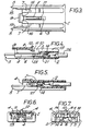
- the connector of Figure 1 comprises a slab-like insulating housing 1 as shown in Figures 2 to 7 adapted to receive three contact receptacles 2 shown in greater detail in Figures 9 to 11.
- the housing 1 is suitably moulded from a resilient insulating material, and comprises a generally rectangular slab-like body 3 having three parallel, open-ended passageways 4 extending between opposite ends, and formed at a forward end with a pair of side extensions 5.
- the body On its underside, as seen in Figure 3, the body is formed with slots 6 and 7 extending rearwardly from the forward end, the slots communicating with respective passageways 4 to define pin-entry apertures.
- the central slot 6 extends rearwardly further than the side slots 7.
- the body 3 is formed with a central resilient latch arm 8 extending rearwardly from a bridge 9 at the forward end of the body.
- the latch arm 8 projects into a slot 10 communicating with the central passageway 4 and terminates at its rear end forwardly of but generally opposite the rear end of the slot 6. At its free rear end the latch arm 8 is formed with a downwardly projecting shoulder portion 11 and an upwardly extending ear portion 12, the shoulder portion 11 presenting a rear facing shoulder spaced forwardly of the rear end of slot 10 and the ear portion 12 projecting outwardly of the slot 10.
- a groove 13 extends rearwardly from the rear of slot 10 in the upper surface of the body 3, to the rear end of the body 3.
- each passageway 4 is of generally T-section having a broad stem portion and a thin head portion, the T-section of the central passageway 4 being inverted and positioned below the outer passageways 4.
- each passageway 4 is formed with a contact retaining shoulder 14 facing forwardly, the shoulder in the central passageway being in the roof of the passageway and those of the outer passageways 4 in the floor.
- the forward side extensions 5 are chamfered on their facing sides at 15 to define a rearwardly convergent path to the outer sides of the outer slots 7, and, as seen in Figure 3, the forward wall of the body 3 bordering the slot 6 at its forward end is formed with convergent surfaces 16 defining a guide into the slot 6.
- the contact receptacle 2 as seen in Figure 1, comprises a receptacle portion 17 extending forwardly from a wire connecting section 18, and is suitably stamped and formed from sheet metal.
- the receptacle section.17 is of fork-like form having a pair of resilient arms 19 extending forwardly in spaced parallel manner from a plate-like mounting section 20, with the wire connecting section 18 extending from a rear of the section 20.
- the wire connecting section and the mounting section 20 are of single metal thickness but the arms 19 are of double metal thickness.
- the wire connecting section comprises a conventional wire crimp ferrule 24 and insulation support ferrule 25, initially of U-form as shown in Figures 9 and 10, and secured by crimping to the core and insulation of insulated conductor wire 26.
- the arms 19 comprising a double metal thickness are formed by folding at outer sides of the arms to define an underside metal layer, and to facilitate the folding, apertures 27 are formed at central portions of the fold lines.
- flanges 28 are folded up from the underside layer, as seen most clearly in Figure 11, to define opposed contact surfaces 29.
- Smaller flanges 30 are folded up from the inner edges of the upper metal layer to support the rear sides of the flanges 28.
- the flanges 28 at their forward ends 31 are folded outwardly in divergent manner, as seen most clearly in Figure 9, to provide a convergent pin-entry into the contact zone between the opposed contact faces 29.
- the flanges 28, as seen in Figure 11, are also dished, or embossed to present arcuately convex facing contact surfaces with a convergent pin-entry from the lower side or from the upper side.
- the contact receptacle 2 as shown in Figures 9 and 10 is shown prior to connection to a conductor wire, and the terminal extends laterally from a carrier strip 36 integrally joined to the insulation support ferrule 25 by a severable neck portion 37.
- Suitably contact receptacles are formed in strip with a plurality of terminals extending laterally at regular intervals from a continuous carrier strip 36 so that they may be applied to respective conductor wires in a terminating machine.
- the contact receptacle 2 is inserted into the central passageway from its rear end in the orientation shown in Figure 1, i.e. with the section 20 engaging the floor of the passageway and the latch 21 projecting upwardly, until the latch 14 engages the forward shoulder 14 to resist withdrawal of the contact rearwardly.
- the ears 22 register on opposite sides of the shoulder and the forward facing shoulders 23 engage complementary shoulders in the housing to resist further forward movement.
- the contact surfaces 29 on flanges 28 are positioned above the rear end of the pin-entry slot 6 to admit upward entry of a pin between the contact surfaces as shown in Figure 8.
- the contact receptacles 2 for the outer passageways 7 are inserted in inverted position with the plate section 20 uppermost and the latch ears 21 projecting downwardly to engage the shoulders 14 on the floors of the passageways as shown in Figure 5.
- a cluster member 32 comprises a triangular array of three parallel spaced pins 33 extending through and on opposite sides of a ceramic disc mounted in a metal annulus 34 secured by welding in an aperture of an hermetic vessel 35 to provide an hermetic seal.
- the connector comprising the housing 1 containing three contact receptacles 2 as described above is assembled to the pins 33 to effect secure electrical connection by moving the connector from the right towards the cluster of pins 33, initially to engage two outer pins 33 between the extensions 5 with the central pin registering with the entrance to the slot 6.
- the chamfered surfaces 15 and 16 serve to guide the pins 33 into the slots 7 and 6 as the connector is moved towards the pins.
- the pins engage the convergent entry surfaces 31 of the contact receptacles to flex the arms 14 apart until the pins are engaged between opposed contact faces 29 of the contact receptacles 2.
- the rear ends of the slots 6, 7 and 10 define stops limiting relative lateral movement of the connector and the pins 33 in this assembly operation and serve to ensure that the pins 33 are properly located with regard to the contact surfaces 29.
- the pin 33 in the central slot 6, during the above assembly operation engages the underside of the shoulder portion 11 of the latch arm 8, camming it upwardly until the pin 33 passes the shoulder portion 11 which relaxes downwardly to engage a side of the pin opposite the rear end of slot 10. This shoulder portion 11 thus resists relative lateral movement between the connector and the pins 33 in an opposite direction.
- the connector may be engaged with or disengaged from the pins 33 in conventional axial manner, the arcuately convex contact surfaces 29, seen in Figure 11, facilitating entry of a pin 33 between the contact surfaces whether the contact receptacle is in the Figure 11 orientation, as in the central passageway 4, or in inverted orientation as in the outer passageways 4.
- the receptacles are stiff in flexure and not only provide high contact force on the pins, but are also resistant to adverse vibration in their operational environment.
- the contact design results in a low height as seen in side elevation and this, together with the inverted arrangement of the central contact relative to the outer contacts, enables a connector of low height to be provided. This is advantageous in the restricted space normally available in installations of the kind for which the connector is intended.
- the central pin is suitably provided with an enlarged head, for example by welding, soldering or otherwise bonding a disc-like cap on the pin.
- the disc-like cap engages the upper side of the receptacle to inhibit axial withdrawal of the connector from the cluster of pins. It will be understood that in such an arrangement, axial mating of the connector with the pins is precluded.
Landscapes
- Connector Housings Or Holding Contact Members (AREA)
- Coupling Device And Connection With Printed Circuit (AREA)
- Multi-Conductor Connections (AREA)
- Details Of Connecting Devices For Male And Female Coupling (AREA)
Applications Claiming Priority (2)
| Application Number | Priority Date | Filing Date | Title |
|---|---|---|---|
| GB8137563 | 1981-12-12 | ||
| GB8137563 | 1981-12-12 |
Publications (3)
| Publication Number | Publication Date |
|---|---|
| EP0081937A2 true EP0081937A2 (de) | 1983-06-22 |
| EP0081937A3 EP0081937A3 (en) | 1983-07-20 |
| EP0081937B1 EP0081937B1 (de) | 1986-04-02 |
Family
ID=10526577
Family Applications (1)
| Application Number | Title | Priority Date | Filing Date |
|---|---|---|---|
| EP82306337A Expired EP0081937B1 (de) | 1981-12-12 | 1982-11-29 | Elektrischer Verbinder und Kontaktsteckdose |
Country Status (3)
| Country | Link |
|---|---|
| EP (1) | EP0081937B1 (de) |
| JP (1) | JPS58108676A (de) |
| DE (1) | DE3270303D1 (de) |
Cited By (3)
| Publication number | Priority date | Publication date | Assignee | Title |
|---|---|---|---|---|
| US5188535A (en) * | 1991-11-18 | 1993-02-23 | Molex Incorporated | Low profile electrical connector |
| EP1045479A1 (de) * | 1999-04-14 | 2000-10-18 | Molex Incorporated | Gestanzte und gebogene Steckverbinderbuchsen |
| US20160204548A1 (en) * | 2015-01-14 | 2016-07-14 | Te Connectivity Germany Gmbh | Contact Preventer For An Electrical Conductor and Assembly For Connecting Two Electrical Conductors |
Families Citing this family (3)
| Publication number | Priority date | Publication date | Assignee | Title |
|---|---|---|---|---|
| JPH081566Y2 (ja) * | 1992-05-19 | 1996-01-17 | エスエムケイ株式会社 | コネクター用フォークコンタクト |
| JP4732173B2 (ja) * | 2006-01-13 | 2011-07-27 | 株式会社水道技術開発機構 | 弁構造およびこれを用いた迂回路形成工法 |
| JP2024179327A (ja) * | 2023-06-14 | 2024-12-26 | 株式会社オートネットワーク技術研究所 | 端子およびコネクタ |
Family Cites Families (6)
| Publication number | Priority date | Publication date | Assignee | Title |
|---|---|---|---|---|
| GB902969A (en) * | 1957-09-24 | 1962-08-09 | Standard Telephones Cables Ltd | Electrical sockets |
| US3101985A (en) * | 1961-02-23 | 1963-08-27 | Products Inc Van | Electrical connector |
| US3336567A (en) * | 1965-07-21 | 1967-08-15 | Amp Inc | Electrical connector |
| ZA712691B (en) * | 1970-05-22 | 1972-01-26 | Amp Inc | Contact element for a printed circuit edge connector |
| US3676829A (en) * | 1970-10-30 | 1972-07-11 | Hubbell Inc Harvey | Contact spring assembly |
| US4253718A (en) * | 1979-09-04 | 1981-03-03 | General Motors Corporation | Electrical connector |
-
1982
- 1982-11-29 EP EP82306337A patent/EP0081937B1/de not_active Expired
- 1982-11-29 DE DE8282306337T patent/DE3270303D1/de not_active Expired
- 1982-12-13 JP JP57218215A patent/JPS58108676A/ja active Granted
Cited By (7)
| Publication number | Priority date | Publication date | Assignee | Title |
|---|---|---|---|---|
| US5188535A (en) * | 1991-11-18 | 1993-02-23 | Molex Incorporated | Low profile electrical connector |
| EP1045479A1 (de) * | 1999-04-14 | 2000-10-18 | Molex Incorporated | Gestanzte und gebogene Steckverbinderbuchsen |
| US20160204548A1 (en) * | 2015-01-14 | 2016-07-14 | Te Connectivity Germany Gmbh | Contact Preventer For An Electrical Conductor and Assembly For Connecting Two Electrical Conductors |
| EP3046186A1 (de) * | 2015-01-14 | 2016-07-20 | TE Connectivity Germany GmbH | Kontaktverhinderer für einen elektrischen leiter und anordnung zur verbindung von zwei elektrischen leitern |
| CN105789968A (zh) * | 2015-01-14 | 2016-07-20 | 泰连德国有限公司 | 用于电导体的触头防护器和用于连接两个电导体的组件 |
| US9923304B2 (en) * | 2015-01-14 | 2018-03-20 | Te Connectivity Germany Gmbh | Contact preventer for an electrical conductor and assembly for connecting two electrical conductors |
| CN105789968B (zh) * | 2015-01-14 | 2020-11-10 | 泰连德国有限公司 | 用于电导体的触头防护器和用于连接两个电导体的组件 |
Also Published As
| Publication number | Publication date |
|---|---|
| EP0081937B1 (de) | 1986-04-02 |
| JPH0326510B2 (de) | 1991-04-11 |
| DE3270303D1 (en) | 1986-05-07 |
| JPS58108676A (ja) | 1983-06-28 |
| EP0081937A3 (en) | 1983-07-20 |
Similar Documents
| Publication | Publication Date | Title |
|---|---|---|
| JPS6223031Y2 (de) | ||
| US4193654A (en) | Electrical connector receptacles | |
| US4221458A (en) | Electrical connector receptacle | |
| US3550067A (en) | Electrical receptacle and terminal | |
| US4460234A (en) | Double-ended modular jack | |
| US4838816A (en) | Electrical terminal having a receptacle contact section of low insertion force | |
| EP0386742B1 (de) | Elektrischer Verbinder mit Buchsenkontakten verschiedener Grössen und Mittel zur Vermeidung von falschem Anschliessen | |
| US4952169A (en) | Sealed electrical connector employing insulation displacement terminals | |
| JPS645754B2 (de) | ||
| JPH03500346A (ja) | レセプタクル電気端子 | |
| KR970018849A (ko) | 단자 수용 통로 수단을 갖는 전기 커넥터 | |
| EP0935827B1 (de) | Kontakt mit verriegelung zur kontakthalterung und dafür geeignetes gehaüse | |
| US4715827A (en) | Modular connector system | |
| US4648678A (en) | Electrical connector | |
| US3842396A (en) | Cluster block housing and pin receptacle | |
| JP2631258B2 (ja) | 過度応力防止手段を有する雄電気端子 | |
| US6010377A (en) | High contact force pin-receiving electrical terminal | |
| US5112244A (en) | Terminal connector | |
| EP0852412A3 (de) | Verbinder für Flachkabel | |
| JPS59217975A (ja) | ブレ−ド型連結端子 | |
| US4895532A (en) | Modular connector coupler with selective commoning system | |
| EP0115425B1 (de) | Verbinderzusammenbau mit innerem Verriegelungssystem | |
| US4439001A (en) | IDC Socket connector | |
| US5433630A (en) | Spring-incorporated flat type terminal structure | |
| EP0081937B1 (de) | Elektrischer Verbinder und Kontaktsteckdose |
Legal Events
| Date | Code | Title | Description |
|---|---|---|---|
| PUAI | Public reference made under article 153(3) epc to a published international application that has entered the european phase |
Free format text: ORIGINAL CODE: 0009012 |
|
| PUAL | Search report despatched |
Free format text: ORIGINAL CODE: 0009013 |
|
| AK | Designated contracting states |
Designated state(s): BE DE FR GB IT NL |
|
| AK | Designated contracting states |
Designated state(s): BE DE FR GB IT NL |
|
| 17P | Request for examination filed |
Effective date: 19830831 |
|
| ITF | It: translation for a ep patent filed | ||
| GRAA | (expected) grant |
Free format text: ORIGINAL CODE: 0009210 |
|
| AK | Designated contracting states |
Kind code of ref document: B1 Designated state(s): BE DE FR GB IT NL |
|
| REF | Corresponds to: |
Ref document number: 3270303 Country of ref document: DE Date of ref document: 19860507 |
|
| ET | Fr: translation filed | ||
| PLBE | No opposition filed within time limit |
Free format text: ORIGINAL CODE: 0009261 |
|
| STAA | Information on the status of an ep patent application or granted ep patent |
Free format text: STATUS: NO OPPOSITION FILED WITHIN TIME LIMIT |
|
| 26N | No opposition filed | ||
| ITTA | It: last paid annual fee | ||
| PGFP | Annual fee paid to national office [announced via postgrant information from national office to epo] |
Ref country code: FR Payment date: 19931015 Year of fee payment: 12 |
|
| PGFP | Annual fee paid to national office [announced via postgrant information from national office to epo] |
Ref country code: BE Payment date: 19931027 Year of fee payment: 12 |
|
| REG | Reference to a national code |
Ref country code: GB Ref legal event code: 732E |
|
| PG25 | Lapsed in a contracting state [announced via postgrant information from national office to epo] |
Ref country code: BE Effective date: 19941130 |
|
| BERE | Be: lapsed |
Owner name: AMP INC. (UNE SOC. DE PENNSYLVANIE) Effective date: 19941130 |
|
| PG25 | Lapsed in a contracting state [announced via postgrant information from national office to epo] |
Ref country code: FR Effective date: 19950731 |
|
| REG | Reference to a national code |
Ref country code: FR Ref legal event code: ST |
|
| PGFP | Annual fee paid to national office [announced via postgrant information from national office to epo] |
Ref country code: NL Payment date: 19951004 Year of fee payment: 14 |
|
| PGFP | Annual fee paid to national office [announced via postgrant information from national office to epo] |
Ref country code: GB Payment date: 19961009 Year of fee payment: 15 |
|
| PGFP | Annual fee paid to national office [announced via postgrant information from national office to epo] |
Ref country code: DE Payment date: 19961128 Year of fee payment: 15 |
|
| PG25 | Lapsed in a contracting state [announced via postgrant information from national office to epo] |
Ref country code: NL Effective date: 19970601 |
|
| NLV4 | Nl: lapsed or anulled due to non-payment of the annual fee |
Effective date: 19970601 |
|
| PG25 | Lapsed in a contracting state [announced via postgrant information from national office to epo] |
Ref country code: GB Free format text: LAPSE BECAUSE OF NON-PAYMENT OF DUE FEES Effective date: 19971129 |
|
| GBPC | Gb: european patent ceased through non-payment of renewal fee |
Effective date: 19971129 |
|
| PG25 | Lapsed in a contracting state [announced via postgrant information from national office to epo] |
Ref country code: DE Free format text: LAPSE BECAUSE OF NON-PAYMENT OF DUE FEES Effective date: 19980801 |