EP0083304A2 - Maschine mit einem intermittierend rotierenden Tisch zur Bearbeitung und Montage von hoch präzisen Teilen - Google Patents
Maschine mit einem intermittierend rotierenden Tisch zur Bearbeitung und Montage von hoch präzisen Teilen Download PDFInfo
- Publication number
- EP0083304A2 EP0083304A2 EP82810547A EP82810547A EP0083304A2 EP 0083304 A2 EP0083304 A2 EP 0083304A2 EP 82810547 A EP82810547 A EP 82810547A EP 82810547 A EP82810547 A EP 82810547A EP 0083304 A2 EP0083304 A2 EP 0083304A2
- Authority
- EP
- European Patent Office
- Prior art keywords
- central shaft
- units
- movement
- shaft
- machine
- Prior art date
- Legal status (The legal status is an assumption and is not a legal conclusion. Google has not performed a legal analysis and makes no representation as to the accuracy of the status listed.)
- Granted
Links
Images



Classifications
-
- B—PERFORMING OPERATIONS; TRANSPORTING
- B23—MACHINE TOOLS; METAL-WORKING NOT OTHERWISE PROVIDED FOR
- B23Q—DETAILS, COMPONENTS, OR ACCESSORIES FOR MACHINE TOOLS, e.g. ARRANGEMENTS FOR COPYING OR CONTROLLING; MACHINE TOOLS IN GENERAL CHARACTERISED BY THE CONSTRUCTION OF PARTICULAR DETAILS OR COMPONENTS; COMBINATIONS OR ASSOCIATIONS OF METAL-WORKING MACHINES, NOT DIRECTED TO A PARTICULAR RESULT
- B23Q39/00—Metal-working machines incorporating a plurality of sub-assemblies, each capable of performing a metal-working operation
- B23Q39/04—Metal-working machines incorporating a plurality of sub-assemblies, each capable of performing a metal-working operation the sub-assemblies being arranged to operate simultaneously at different stations, e.g. with an annular work-table moved in steps
- B23Q39/042—Metal-working machines incorporating a plurality of sub-assemblies, each capable of performing a metal-working operation the sub-assemblies being arranged to operate simultaneously at different stations, e.g. with an annular work-table moved in steps with circular arrangement of the sub-assemblies
-
- B—PERFORMING OPERATIONS; TRANSPORTING
- B23—MACHINE TOOLS; METAL-WORKING NOT OTHERWISE PROVIDED FOR
- B23P—METAL-WORKING NOT OTHERWISE PROVIDED FOR; COMBINED OPERATIONS; UNIVERSAL MACHINE TOOLS
- B23P21/00—Machines for assembling a multiplicity of different parts to compose units, with or without preceding or subsequent working of such parts, e.g. with program control
- B23P21/004—Machines for assembling a multiplicity of different parts to compose units, with or without preceding or subsequent working of such parts, e.g. with program control the units passing two or more work-stations whilst being composed
- B23P21/006—Machines for assembling a multiplicity of different parts to compose units, with or without preceding or subsequent working of such parts, e.g. with program control the units passing two or more work-stations whilst being composed the conveying means comprising a rotating table
-
- Y—GENERAL TAGGING OF NEW TECHNOLOGICAL DEVELOPMENTS; GENERAL TAGGING OF CROSS-SECTIONAL TECHNOLOGIES SPANNING OVER SEVERAL SECTIONS OF THE IPC; TECHNICAL SUBJECTS COVERED BY FORMER USPC CROSS-REFERENCE ART COLLECTIONS [XRACs] AND DIGESTS
- Y10—TECHNICAL SUBJECTS COVERED BY FORMER USPC
- Y10T—TECHNICAL SUBJECTS COVERED BY FORMER US CLASSIFICATION
- Y10T29/00—Metal working
- Y10T29/51—Plural diverse manufacturing apparatus including means for metal shaping or assembling
- Y10T29/5124—Plural diverse manufacturing apparatus including means for metal shaping or assembling with means to feed work intermittently from one tool station to another
- Y10T29/5127—Blank turret
- Y10T29/5128—Rotary work - vertical axis
-
- Y—GENERAL TAGGING OF NEW TECHNOLOGICAL DEVELOPMENTS; GENERAL TAGGING OF CROSS-SECTIONAL TECHNOLOGIES SPANNING OVER SEVERAL SECTIONS OF THE IPC; TECHNICAL SUBJECTS COVERED BY FORMER USPC CROSS-REFERENCE ART COLLECTIONS [XRACs] AND DIGESTS
- Y10—TECHNICAL SUBJECTS COVERED BY FORMER USPC
- Y10T—TECHNICAL SUBJECTS COVERED BY FORMER US CLASSIFICATION
- Y10T29/00—Metal working
- Y10T29/51—Plural diverse manufacturing apparatus including means for metal shaping or assembling
- Y10T29/5152—Plural diverse manufacturing apparatus including means for metal shaping or assembling with turret mechanism
- Y10T29/5154—Plural diverse manufacturing apparatus including means for metal shaping or assembling with turret mechanism tool turret
- Y10T29/5157—Sliding tool holder
-
- Y—GENERAL TAGGING OF NEW TECHNOLOGICAL DEVELOPMENTS; GENERAL TAGGING OF CROSS-SECTIONAL TECHNOLOGIES SPANNING OVER SEVERAL SECTIONS OF THE IPC; TECHNICAL SUBJECTS COVERED BY FORMER USPC CROSS-REFERENCE ART COLLECTIONS [XRACs] AND DIGESTS
- Y10—TECHNICAL SUBJECTS COVERED BY FORMER USPC
- Y10T—TECHNICAL SUBJECTS COVERED BY FORMER US CLASSIFICATION
- Y10T29/00—Metal working
- Y10T29/51—Plural diverse manufacturing apparatus including means for metal shaping or assembling
- Y10T29/5152—Plural diverse manufacturing apparatus including means for metal shaping or assembling with turret mechanism
- Y10T29/5154—Plural diverse manufacturing apparatus including means for metal shaping or assembling with turret mechanism tool turret
- Y10T29/5159—Cam operated
- Y10T29/516—Longitudinal turret axis
-
- Y—GENERAL TAGGING OF NEW TECHNOLOGICAL DEVELOPMENTS; GENERAL TAGGING OF CROSS-SECTIONAL TECHNOLOGIES SPANNING OVER SEVERAL SECTIONS OF THE IPC; TECHNICAL SUBJECTS COVERED BY FORMER USPC CROSS-REFERENCE ART COLLECTIONS [XRACs] AND DIGESTS
- Y10—TECHNICAL SUBJECTS COVERED BY FORMER USPC
- Y10T—TECHNICAL SUBJECTS COVERED BY FORMER US CLASSIFICATION
- Y10T29/00—Metal working
- Y10T29/51—Plural diverse manufacturing apparatus including means for metal shaping or assembling
- Y10T29/5152—Plural diverse manufacturing apparatus including means for metal shaping or assembling with turret mechanism
- Y10T29/5154—Plural diverse manufacturing apparatus including means for metal shaping or assembling with turret mechanism tool turret
- Y10T29/5162—Lever operated
-
- Y—GENERAL TAGGING OF NEW TECHNOLOGICAL DEVELOPMENTS; GENERAL TAGGING OF CROSS-SECTIONAL TECHNOLOGIES SPANNING OVER SEVERAL SECTIONS OF THE IPC; TECHNICAL SUBJECTS COVERED BY FORMER USPC CROSS-REFERENCE ART COLLECTIONS [XRACs] AND DIGESTS
- Y10—TECHNICAL SUBJECTS COVERED BY FORMER USPC
- Y10T—TECHNICAL SUBJECTS COVERED BY FORMER US CLASSIFICATION
- Y10T409/00—Gear cutting, milling, or planing
- Y10T409/30—Milling
- Y10T409/306048—Milling with means to advance work or product
- Y10T409/306104—Endless or orbital work or product advancing means
-
- Y—GENERAL TAGGING OF NEW TECHNOLOGICAL DEVELOPMENTS; GENERAL TAGGING OF CROSS-SECTIONAL TECHNOLOGIES SPANNING OVER SEVERAL SECTIONS OF THE IPC; TECHNICAL SUBJECTS COVERED BY FORMER USPC CROSS-REFERENCE ART COLLECTIONS [XRACs] AND DIGESTS
- Y10—TECHNICAL SUBJECTS COVERED BY FORMER USPC
- Y10T—TECHNICAL SUBJECTS COVERED BY FORMER US CLASSIFICATION
- Y10T82/00—Turning
- Y10T82/25—Lathe
- Y10T82/2511—Vertical
Definitions
- This invention has as its object a machine with an intermittently rotating table for working and assembly of high-precision parts in three axes.
- Machines with an intermittently rotating table for working and mounting of high-precision parts such as electrical contacts, small metal parts, points of ball point pens, etc., are known.
- the machine according to the present invention differs from known ones by the fact that it makes it possible to give to the operating units any feed and return characteristic as occurs in machines with rotary cams, while having very simplified kinematics and working in three different axes.
- control organs are in the center of the machine, it offers a complete accessibility to the tools and the parts to be worked.
- the machine according to this invention comprises working units placed above, below and laterally with respect to the rotary table with intermittent movement. Control of the feeds of the units to be worked occurs by a central shaft that is coaxial with the rotary table.
- the machine is characterized by the characterizing part of claim 1.
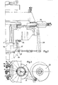
- Auxiliary shaft 2 controls maltese cross device 6, 7, which changes the continuous movement into an intermittent movement for driving table 8.
- auxiliary cam 2 To the base of auxiliary cam 2 is fastened drum cam 9 which, by acting on rollers 10, causes the axial movement of central shaft 4. Also to auxiliary.shaft 2 is fastened another drum cam 11 that controls indexing of table 8 by rollers 12 and rod 13.
- central shaft 4 To both ends of central shaft 4 are fastened cylindrical bodies 14 and 15 on which are secured radial linear cams 16-17 (see also Fig. 3). These cams, by rollers 18, 18' and levers 19, 19', control the movement of operating units 20-21.
- the operating units can receive the rotary movement from a central wheel 22 or an independent small motor 21'.
- central shaft 4 makes a downward movement and in this phase cams 16-17 are in contact with rollers 18, 18' of levers 19, 19' which control the movement of operating units 20, 21.
- central shaft 4 is turned a certain angle by cam 23 (fastened to auxiliary shaft 3) and lever 24.
- linear cams 16-17 are no longer in contact with rollers 18, 18' and therefore no longer control the operating units (20, 21) and return of central shaft 4 occurs without influencing the operating units themselves.
- central shaft 4 is rotated to its starting position. Return and rotation of central shaft 4 occur in idle times, i.e., during the rotation and indexing of table 8.
- levers 19, 19' rest on stops 24, 24'.
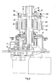
- Fig. 2 shows on a larger scale an axial section of the control organs of a lateral station 25.
- Operating unit 25 receives the,feed control from linear cam 26 by roller 27 and lever arrangement 28.
- Fig. 3 shows, for greater clarity, in plane view, in the right half, elements 23, 24 located in the lower part of the machine that control central shaft 4, and in the left half, elements 16, 18', 19' located in the upper part of the machine itself and which control the axial movements of operating units 20.
- Figures 4 and 5 represent a particular embodiment of the maltese cross device.
- the maltese cross as is known, is a very simple mechanism for generating an intermittent movement from a continuous rotary movement.
- the disadvantage is that the low of translation is fixed, i.e., it depends only on its angular subdivision.
- the mechanism described here makes it possible to eliminate this drawback and reduce the angle of rotation necessary for indexing and also to modify the characteristic of the movement itself.
- Toothed segment 40 carries roller 38 that in turn is guided by cam 39.
- Cam 39 has such a geometry that during translation of the table is accelerates toothed segment 40, thus superposing a relative rotary movement on cogwheel 41 and therefore on shaft 35 which controls the maltese cross device.
- Figures 6, 7 represent a simpler variant of the machine in question especially suited to mounting and working of small parts that require only vertical operating units.
- the machine comprises: first elements 9, 10 able to impart the axial movement to central shaft 4, second elements: 34, 29, 14, 30, 32 able to connect each working unit 20, 20' to said central shaft to control the feed of each unit directly, using the axial movement of said central shaft, and third elements 19', 31 able to connect each work unit to said central shaft, by intermediate elements 16, 18', to control the feed of each work until 20, 20' indirectly, independently of the others, still using the axial movement of said central shaft 4.
- the machine comprises: central shaft 4 controlling the feed of the work units.
- the movement is still supplied by motor 1 which transmits it to auxiliary shaft 2 parallel to central shaft 4 by the speed reducer.
- Shaft 2 controls maltese cross device 6', 7', 7", (also see figure 7) which transforms the continuous rotary movement into an intermittent movement to drive rotary table 8.
- central shaft 4 At the top of central shaft 4 is fastened bushing 14, which, by lever 34, engages in groove 30 of micrometrically adjustable support 29, 29' of the corresponding work unit 20, 20'.
- this makes it possible to operate it, i.e., to make it travel axially upward and downward along support 33 by the bearing elements generally indicated by 32, 32' and preferably consisting of a ball cage.
- Another group of elements comprises, for each work unit, a linear cam 16, solid with bushing 14; roller 18', located at the end of square lever 19', travels on this cam; the other end of the lever is connected to support 29' carrying the corresponding work unit 20'.
- central shaft 4 is quickly brought back to its initial position before executing the translation of rotary table 8. That is necessary to bring work units 20, 20' back to the initial position, without contact with the parts to be worked.
Landscapes
- Engineering & Computer Science (AREA)
- Mechanical Engineering (AREA)
- Transmission Devices (AREA)
- Machine Tool Positioning Apparatuses (AREA)
Priority Applications (1)
| Application Number | Priority Date | Filing Date | Title |
|---|---|---|---|
| AT82810547T ATE25938T1 (de) | 1981-12-28 | 1982-12-17 | Maschine mit einem intermittierend rotierenden tisch zur bearbeitung und montage von hoch praezisen teilen. |
Applications Claiming Priority (4)
| Application Number | Priority Date | Filing Date | Title |
|---|---|---|---|
| CH8302/81 | 1981-12-28 | ||
| CH830281A CH671910A5 (en) | 1981-12-28 | 1981-12-28 | Machine with intermittently rotary table |
| CH8319/81 | 1981-12-29 | ||
| CH831981 | 1981-12-29 |
Publications (3)
| Publication Number | Publication Date |
|---|---|
| EP0083304A2 true EP0083304A2 (de) | 1983-07-06 |
| EP0083304A3 EP0083304A3 (en) | 1985-07-03 |
| EP0083304B1 EP0083304B1 (de) | 1987-03-18 |
Family
ID=25703125
Family Applications (1)
| Application Number | Title | Priority Date | Filing Date |
|---|---|---|---|
| EP82810547A Expired EP0083304B1 (de) | 1981-12-28 | 1982-12-17 | Maschine mit einem intermittierend rotierenden Tisch zur Bearbeitung und Montage von hoch präzisen Teilen |
Country Status (3)
| Country | Link |
|---|---|
| US (1) | US4523359A (de) |
| EP (1) | EP0083304B1 (de) |
| DE (1) | DE3275709D1 (de) |
Cited By (5)
| Publication number | Priority date | Publication date | Assignee | Title |
|---|---|---|---|---|
| US4862569A (en) * | 1988-03-08 | 1989-09-05 | Azypatent Ag | Machine with a table with intermittent rotation |
| EP0437176A3 (en) * | 1990-01-12 | 1991-12-27 | Mikron S.A. | Machine with intermittently rotary workpiece-holding table for working and assembly of high-precision pieces |
| JPH07256533A (ja) * | 1990-01-23 | 1995-10-09 | Mikron Sa | 高精密部品の加工組立装置 |
| WO2003011505A3 (de) * | 2001-07-24 | 2003-10-09 | Mauser Werke Oberndorf Maschb | Einrichtung zum bruchttrennen von werkstücken |
| DE4230785B4 (de) * | 1992-09-15 | 2006-07-06 | Pfuderer, Markus | Montagemaschine |
Families Citing this family (8)
| Publication number | Priority date | Publication date | Assignee | Title |
|---|---|---|---|---|
| US4833763A (en) * | 1987-02-03 | 1989-05-30 | Kurt Jauch | Multistation working machine |
| US6081986A (en) * | 1996-12-05 | 2000-07-04 | Miyano; Toshiharu Tom | Automated machine tool including a plurality of processing units |
| EP0989922B1 (de) * | 1997-06-21 | 2003-09-03 | Feintool International Holding | Montage- oder fertigungsautomat und arbeitsstation für einen solchen automaten |
| DE19835954A1 (de) * | 1998-08-08 | 2000-02-17 | Index Werke Kg Hahn & Tessky | Werkzeugmaschine |
| DE10006934B4 (de) * | 2000-02-16 | 2004-12-23 | Feintool International Holding | Fertigungs- und/oder Montageautomat |
| US6219895B1 (en) * | 2000-06-27 | 2001-04-24 | Davenport Industries, Llc | Machine tool with servo drive mechanism |
| DE202011003069U1 (de) * | 2011-02-17 | 2011-04-28 | Kadia Produktion Gmbh + Co. | Vorrichtung zur mechanischen Oberflächenbearbeitung von Werkstücken |
| CN113078029B (zh) * | 2021-02-26 | 2022-04-29 | 旺荣电子(深圳)有限公司 | 一种继电器触点安装机构 |
Family Cites Families (9)
| Publication number | Priority date | Publication date | Assignee | Title |
|---|---|---|---|---|
| US1825971A (en) * | 1928-06-01 | 1931-10-06 | Nat Automatic Tool Co | Drill unit with common feed |
| US1907550A (en) * | 1931-01-02 | 1933-05-09 | Pratt & Whitney Co | Vertical spindle machine tool |
| US2272055A (en) * | 1939-04-12 | 1942-02-03 | Gustave A Carlson | Polishing and grinding machine |
| DE921609C (de) * | 1948-10-02 | 1954-12-23 | Siemens Ag | Mehrzweckfertigungs-, Fuege- und Pruefmaschine |
| DE1258707B (de) * | 1959-03-04 | 1968-01-11 | Josef Maurer | Schalttischmaschine fuer die spanabhebende Bearbeitung von Kleinteilen |
| US3591913A (en) * | 1968-11-14 | 1971-07-13 | James W Lewis | Reciprocating and oscillating toolplate machine |
| CH525065A (it) * | 1970-04-10 | 1972-07-15 | Albe Sa | Macchina per la lavorazione meccanica in grande serie e con estrema precisione di oggetti di piccole dimensioni e di forma complicata, in particolare di minuterie metalliche |
| CH528949A (it) * | 1971-09-30 | 1972-10-15 | Albe Sa | Macchina per la lavorazione automatica di piccoli pezzi anche di forma complicata |
| CH614148A5 (de) * | 1977-05-26 | 1979-11-15 | Haesler Mikron |
-
1982
- 1982-12-17 DE DE8282810547T patent/DE3275709D1/de not_active Expired
- 1982-12-17 EP EP82810547A patent/EP0083304B1/de not_active Expired
- 1982-12-28 US US06/454,081 patent/US4523359A/en not_active Expired - Lifetime
Cited By (6)
| Publication number | Priority date | Publication date | Assignee | Title |
|---|---|---|---|---|
| US4862569A (en) * | 1988-03-08 | 1989-09-05 | Azypatent Ag | Machine with a table with intermittent rotation |
| EP0437176A3 (en) * | 1990-01-12 | 1991-12-27 | Mikron S.A. | Machine with intermittently rotary workpiece-holding table for working and assembly of high-precision pieces |
| US5097577A (en) * | 1990-01-12 | 1992-03-24 | Mikron S.A. | Machine with intermittently rotary workpiece-holding table for working and assembly of high-precision pieces |
| JPH07256533A (ja) * | 1990-01-23 | 1995-10-09 | Mikron Sa | 高精密部品の加工組立装置 |
| DE4230785B4 (de) * | 1992-09-15 | 2006-07-06 | Pfuderer, Markus | Montagemaschine |
| WO2003011505A3 (de) * | 2001-07-24 | 2003-10-09 | Mauser Werke Oberndorf Maschb | Einrichtung zum bruchttrennen von werkstücken |
Also Published As
| Publication number | Publication date |
|---|---|
| EP0083304B1 (de) | 1987-03-18 |
| US4523359A (en) | 1985-06-18 |
| DE3275709D1 (en) | 1987-04-23 |
| EP0083304A3 (en) | 1985-07-03 |
Similar Documents
| Publication | Publication Date | Title |
|---|---|---|
| EP0083304A2 (de) | Maschine mit einem intermittierend rotierenden Tisch zur Bearbeitung und Montage von hoch präzisen Teilen | |
| KR910007021Y1 (ko) | 나사가공장치 | |
| KR870009813A (ko) | 변속과 이송속도를 따로 가진 다축스핀들 머신과 가공물의 기계가공방법 | |
| US4862569A (en) | Machine with a table with intermittent rotation | |
| US2376476A (en) | Automatic screw machine | |
| US5092021A (en) | Intermittently rotary workpiece-holding table for working and assembly | |
| US2284319A (en) | Cam forming fixture | |
| US3044367A (en) | Double end tube deburring machine | |
| GB1251123A (de) | ||
| US3533306A (en) | Programming apparatus for machine tools or the like | |
| US2574775A (en) | Automatic lathe headstock reciprocating means | |
| US3890863A (en) | Stamping machine for slotting core plates | |
| DE102013106784B4 (de) | Vorrichtung und Verfahren zum Umformen von hohlzylindrischen Körpern | |
| US4075897A (en) | Apparatus for obtaining relative orbital movement in electrical discharge machining | |
| US2208319A (en) | Lathe | |
| SU1024218A1 (ru) | Привод суппортов и балансира токарного станка | |
| DE506943C (de) | Vorrichtung zur Herstellung elliptischer Werkstuecke | |
| US3625073A (en) | Automatic lathes | |
| US1482621A (en) | Screw and gear making machine | |
| SU1066760A1 (ru) | Устройство дл образовани винтовых канавок на изделии | |
| US2360497A (en) | Motion transmitting mechanism | |
| US2251033A (en) | Lapping machine | |
| US3390583A (en) | Indexing-cam mechanism | |
| KR820001539B1 (ko) | 축방향과 방사상으로 동시에 공작물을 절삭하는 회전기 | |
| SU691283A2 (ru) | Устройство дл доводки (суперфиниша) желобчатых поверхностей колец шариковых подщипников |
Legal Events
| Date | Code | Title | Description |
|---|---|---|---|
| PUAI | Public reference made under article 153(3) epc to a published international application that has entered the european phase |
Free format text: ORIGINAL CODE: 0009012 |
|
| AK | Designated contracting states |
Designated state(s): AT BE CH DE FR GB IT LI LU NL SE |
|
| PUAL | Search report despatched |
Free format text: ORIGINAL CODE: 0009013 |
|
| AK | Designated contracting states |
Designated state(s): AT BE CH DE FR GB IT LI LU NL SE |
|
| 17P | Request for examination filed |
Effective date: 19850628 |
|
| 17Q | First examination report despatched |
Effective date: 19860217 |
|
| ITF | It: translation for a ep patent filed | ||
| GRAA | (expected) grant |
Free format text: ORIGINAL CODE: 0009210 |
|
| AK | Designated contracting states |
Kind code of ref document: B1 Designated state(s): AT BE CH DE FR GB IT LI LU NL SE |
|
| REF | Corresponds to: |
Ref document number: 25938 Country of ref document: AT Date of ref document: 19870415 Kind code of ref document: T |
|
| REF | Corresponds to: |
Ref document number: 3275709 Country of ref document: DE Date of ref document: 19870423 |
|
| ET | Fr: translation filed | ||
| PLBE | No opposition filed within time limit |
Free format text: ORIGINAL CODE: 0009261 |
|
| STAA | Information on the status of an ep patent application or granted ep patent |
Free format text: STATUS: NO OPPOSITION FILED WITHIN TIME LIMIT |
|
| 26N | No opposition filed | ||
| REG | Reference to a national code |
Ref country code: CH Ref legal event code: PUE Owner name: MIKRON S.A. |
|
| ITPR | It: changes in ownership of a european patent |
Owner name: CESSIONE;MIKRON S.A. AGNO |
|
| NLS | Nl: assignments of ep-patents |
Owner name: MIKRON S.A. TE AGNO, ZWITSERLAND. |
|
| REG | Reference to a national code |
Ref country code: FR Ref legal event code: TP |
|
| PGFP | Annual fee paid to national office [announced via postgrant information from national office to epo] |
Ref country code: LU Payment date: 19911218 Year of fee payment: 10 |
|
| PGFP | Annual fee paid to national office [announced via postgrant information from national office to epo] |
Ref country code: AT Payment date: 19911220 Year of fee payment: 10 |
|
| PGFP | Annual fee paid to national office [announced via postgrant information from national office to epo] |
Ref country code: NL Payment date: 19911231 Year of fee payment: 10 |
|
| REG | Reference to a national code |
Ref country code: GB Ref legal event code: 732 |
|
| EPTA | Lu: last paid annual fee | ||
| PG25 | Lapsed in a contracting state [announced via postgrant information from national office to epo] |
Ref country code: LU Free format text: LAPSE BECAUSE OF NON-PAYMENT OF DUE FEES Effective date: 19921217 Ref country code: AT Effective date: 19921217 |
|
| PG25 | Lapsed in a contracting state [announced via postgrant information from national office to epo] |
Ref country code: NL Effective date: 19930701 |
|
| NLV4 | Nl: lapsed or anulled due to non-payment of the annual fee | ||
| ITTA | It: last paid annual fee | ||
| EAL | Se: european patent in force in sweden |
Ref document number: 82810547.8 |
|
| PGFP | Annual fee paid to national office [announced via postgrant information from national office to epo] |
Ref country code: CH Payment date: 20011219 Year of fee payment: 20 |
|
| PGFP | Annual fee paid to national office [announced via postgrant information from national office to epo] |
Ref country code: SE Payment date: 20011220 Year of fee payment: 20 Ref country code: GB Payment date: 20011220 Year of fee payment: 20 Ref country code: DE Payment date: 20011220 Year of fee payment: 20 |
|
| PGFP | Annual fee paid to national office [announced via postgrant information from national office to epo] |
Ref country code: BE Payment date: 20011221 Year of fee payment: 20 |
|
| PGFP | Annual fee paid to national office [announced via postgrant information from national office to epo] |
Ref country code: FR Payment date: 20011231 Year of fee payment: 20 |
|
| REG | Reference to a national code |
Ref country code: GB Ref legal event code: IF02 |
|
| PG25 | Lapsed in a contracting state [announced via postgrant information from national office to epo] |
Ref country code: LI Free format text: LAPSE BECAUSE OF EXPIRATION OF PROTECTION Effective date: 20021216 Ref country code: GB Free format text: LAPSE BECAUSE OF EXPIRATION OF PROTECTION Effective date: 20021216 Ref country code: CH Free format text: LAPSE BECAUSE OF EXPIRATION OF PROTECTION Effective date: 20021216 |
|
| BE20 | Be: patent expired |
Owner name: S.A. *MIKRON AGNO Effective date: 20021217 |
|
| REG | Reference to a national code |
Ref country code: GB Ref legal event code: PE20 Effective date: 20021216 |
|
| REG | Reference to a national code |
Ref country code: CH Ref legal event code: PL |
|
| EUG | Se: european patent has lapsed |