EP0084077A2 - Dispositif pour transporter automatiquement des plaques supports circuits imprimés à des installations d'étendage au rouleau - Google Patents
Dispositif pour transporter automatiquement des plaques supports circuits imprimés à des installations d'étendage au rouleau Download PDFInfo
- Publication number
- EP0084077A2 EP0084077A2 EP82102260A EP82102260A EP0084077A2 EP 0084077 A2 EP0084077 A2 EP 0084077A2 EP 82102260 A EP82102260 A EP 82102260A EP 82102260 A EP82102260 A EP 82102260A EP 0084077 A2 EP0084077 A2 EP 0084077A2
- Authority
- EP
- European Patent Office
- Prior art keywords
- grippers
- gripper
- horizontal
- plate
- parallel
- Prior art date
- Legal status (The legal status is an assumption and is not a legal conclusion. Google has not performed a legal analysis and makes no representation as to the accuracy of the status listed.)
- Granted
Links
- 238000009434 installation Methods 0.000 title 1
- 230000008719 thickening Effects 0.000 claims description 2
- 238000005096 rolling process Methods 0.000 abstract description 6
- 230000006835 compression Effects 0.000 description 3
- 238000007906 compression Methods 0.000 description 3
- 230000001681 protective effect Effects 0.000 description 3
- 229920000742 Cotton Polymers 0.000 description 2
- 238000004140 cleaning Methods 0.000 description 2
- 238000000034 method Methods 0.000 description 2
- 238000004378 air conditioning Methods 0.000 description 1
- 235000015115 caffè latte Nutrition 0.000 description 1
- 238000011109 contamination Methods 0.000 description 1
- 238000006073 displacement reaction Methods 0.000 description 1
- 238000001035 drying Methods 0.000 description 1
- 238000009415 formwork Methods 0.000 description 1
- 230000001788 irregular Effects 0.000 description 1
- 238000011031 large-scale manufacturing process Methods 0.000 description 1
- 229920002120 photoresistant polymer Polymers 0.000 description 1
- 238000005406 washing Methods 0.000 description 1
Images


Classifications
-
- G—PHYSICS
- G03—PHOTOGRAPHY; CINEMATOGRAPHY; ANALOGOUS TECHNIQUES USING WAVES OTHER THAN OPTICAL WAVES; ELECTROGRAPHY; HOLOGRAPHY
- G03F—PHOTOMECHANICAL PRODUCTION OF TEXTURED OR PATTERNED SURFACES, e.g. FOR PRINTING, FOR PROCESSING OF SEMICONDUCTOR DEVICES; MATERIALS THEREFOR; ORIGINALS THEREFOR; APPARATUS SPECIALLY ADAPTED THEREFOR
- G03F7/00—Photomechanical, e.g. photolithographic, production of textured or patterned surfaces, e.g. printing surfaces; Materials therefor, e.g. comprising photoresists; Apparatus specially adapted therefor
- G03F7/16—Coating processes; Apparatus therefor
Definitions
- the above invention relates to a device for automatically feeding carrier plates for printed, electrical circuits to a subsequent film rolling device.
- carrier plates for printed circuits after they have been subjected to cleaning, washing and drying, and after these plates have been stacked, are fed to a so-called film roller device, in which a film is applied to the carrier plate and used to carry out the known photoresist -Procedure is required.
- the object of the above invention is to avoid the disadvantages of the prior art and to propose a device with which, without coming into contact with the surfaces of the mounted plates, an automatic, rapid feeding of these plates with precision and security to a film reeling device becomes possible.
- a holding device which can be moved back and forth in a vertical direction relative to the stack of plates is provided above a carrier plate stack, in that this holding device has two parallel, horizontal guide rods, which on their opposite sides. Take up the ends of the piston cylinder in the internal units, the piston rods of which hold parallel, horizontal cross members, at the free end of which adjustable grippers are provided which can be moved in both the horizontal and vertical directions and that a corresponding, parallel to each horizontal cross member which receives the grippers operable and slidable roller conveyor is arranged, which can be moved in a horizontal plane, from a rest position into a working position and vice versa, in which working position the carrier plates are transferred to the roller conveyor by the grippers will.
- the grippers are each assigned to two parallel longitudinal edges of the carrier plate.
- the device according to the invention consists of a support housing 2 which is operatively connected to the piston rod 3 of a pneumatic cylinder 4 or a similar drive means.
- the end 4a of the pneumatic cylinder is z.8. connected to a support frame, not shown, of the machine.
- the support housing 2 receives in horizontal, parallel bores, guide rods 5 and 6, which are displaceable relative to the housing 2 and can be fixed in the desired position, for example by knurled head screws 7 and 8.
- the possibility of moving the handrails 5 and 6 proves to be particularly advantageous when setting and aligning of these rods, taking into account the dimensions of the carrier plate 9 to be accommodated.
- the displaceable holding rods 5 and 6 have thickenings 10, 11 which receive the fastening flange of a corresponding piston-cylinder unit 12, 13.
- the piston rods 1.4, 15 of the piston-cylinder units 12, 13 are operatively connected to further brackets 16 and 17 which receive a corresponding horizontally arranged cross strut 18 and 19, respectively.
- retaining blocks 21 are arranged, which can be adjusted, for example using hat bolts 20, and their position can be fixed. Due to the possibility of moving the holding blocks 21 along the cross struts 18 and 19, it is in turn possible to adjust the brackets 21, taking into account the dimensions of the support plate 9.
- Each holder 21 is equipped with a gripper, which is designated overall by 22 in FIG. 1. 1, for reasons of clarity, only one gripping unit 22 is shown, but it is obvious that all holding blocks 21 are equipped with such grippers 22.
- the gripper unit 22 consists of a support plate 23 which slides over a vertical bolt 24 in a vertical guide sleeve 25, which is arranged in the holding block.
- a compression spring 26 is arranged on the bolt 24, which it the holding plate 23 makes it possible to carry out a vertical movement in the vertical direction by overcoming the spring force of the spring means 26.
- the holding plate 23 advantageously has a dovetail groove 27, and in this groove 27, a corresponding counter profile slides, which is made in one piece with the gripper 28.
- the gripper 28 has on its upper side a vertical plate 29 which receives a bolt 33 which is slidably guided in the horizontally arranged plate 23, and, between this carrier plate 23 and the vertical projections 29, a compression spring 31 is provided in order to to enable the gripper 28 to perform a movement in the horizontal direction against the force of the spring 31.
- the gripper 28 On the front side, the gripper 28 has an inclined plane 28a, which ends in the tapered projection 28b on the underside. The purpose of these devices will be explained in more detail in the following description.
- the plate stack 9 is located on a lifting table which can execute a defined movement in the vertical direction, thereby ensuring that the top plate 9 is always at the same height with respect to the grippers 28 is located, in accordance with the inclined plane 28a and the tapered projections 28b.
- roller tracks are assigned to it, which are movable in a horizontal plane, two roller tracks each being assigned parallel cross struts.
- this roller courses are not shown, their training can more precisely the Figg. 4 and 5 are taken.
- Fig. 4 two arranged horizontal roller courses are shown, which are assigned to the device 1 and in this pictorial representation, only gripper groups 22 are shown, whereas the individual holding devices, piston cylinder units and carrying means have not been shown for reasons of clarity.
- roller courses 32 and 33 are provided which accommodate a number of rollers in housings 34 and 35, for example, which are accommodated by the machine frame (not shown), with their axes of rotation in the housings 34 and 35 are mounted, and are driven such that the support plate 9 in the direction of the arrow f are movable.
- the rollers 36 advantageously have the shape of two cone pumps 36a and 36b, which are joined together with their tapered sections, this connection being provided approximately at the height of the carrier plate 9.
- the housings 32 and 33 which are arranged to be movable in the horizontal direction, furthermore have openings 37 into which the gripper groups 22 can enter during the movement of the roller tracks 32 and 33 in a horizontal plane, as indicated by the double arrows g.
- the roller conveyors are advantageously equipped with piston-cylinder units which can be actuated, for example, by compressed air and are arranged firmly on the frame of the machine (not shown).
- FIG. 5 shows a detail of a roller 36 with the inclined surfaces 36a and 36b.
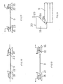
- the grippers 22 are already arranged above the plate stack 9, which is located under the grippers, and the rollers 36 of the roller tracks 32 and 33 are set at a maximum distance.
- the piston-cylinder unit 3, 4 By actuating the piston-cylinder unit 3, 4, all the grippers 22 are moved downwards onto the plate stack, as a result of which the inclined surfaces 28b of the grippers 22 come into contact with the upper, parallel corner edges of the uppermost plate 9 (support).
- the contact between the inclined surfaces 28a and the upper corner edges of the uppermost plate 9 is gradual, gentle and safe, even in the case of discarded plates, because of that this possibility of displacement in the vertical direction, also irregularities of the plate 9 with respect to the horizontal plane, are compensated for.
- each gripper element 28 can carry out an elastic movement in the horizontal direction. This is made possible by the provision of the dovetail guide 27, the guide rod 30, and the compression spring 31, which is arranged between the carrier 23 and the projection 29 of the gripping body 28.
- the uppermost support plate 9 is gripped by the tapered projections 28b even in the case of plates which are not precisely cut and which may have an irregular circumference.
- the piston-cylinder unit 3, 4 is driven again to bring the plate, as shown in FIG. 9, into a plane that approximately constricts corresponds to the roller 36 and is formed between the truncated cones 36a and 36b.
- the roller conveyors 32 and 33 are also displaced in the horizontal plane and moved in the direction of the carrier plate 9 blocked by the grippers 22.
- the grippers 22 can enter the openings 3 7 of the housings 34 and 35 provided for this purpose, as is shown schematically in FIG. 4 is shown.
- the piston-cylinder units 12, 14 and 13, 15 are driven again, and the grippers 22 are spaced apart, as shown in FIG. 11.
- the roller courses 32 and 33 are again spaced apart, as shown in FIG. 12.
- the special embodiment of the gripper 22 can be seen on an enlarged scale.
- the gripper 22 comes into contact with the upper corner edge of the uppermost plate 9 and rests on this corner edge with its inclined surface 26b.
- the tapered provision 28b comes into contact with the associated vertical edge of the plate 9 and thus clamps the plate.
- an advantageous combination between positive and non-positive fixing of the carrier plate 9 between the grippers 22 and the carrier plate 9 can thus be quickly and safely raised in order to, with the aid of the roller gears previously described, the are arranged movably in the horizontal direction, are fed to a subsequent film roller device which applies a photosensitive film to the carrier plate.
- the provision of the device according to the invention makes it possible to significantly reduce the size of the air-conditioned spaces in which the stacks of support plates 9 to be loaded are provided, and these air-conditioned spaces can be completely encapsulated.
Landscapes
- Physics & Mathematics (AREA)
- General Physics & Mathematics (AREA)
- Sheets, Magazines, And Separation Thereof (AREA)
- Replacement Of Web Rolls (AREA)
- Specific Conveyance Elements (AREA)
Priority Applications (1)
| Application Number | Priority Date | Filing Date | Title |
|---|---|---|---|
| AT82102260T ATE21780T1 (de) | 1982-01-07 | 1982-03-19 | Vorrichtung zum automatischen beschicken von traegerplatten fuer gedruckte schaltungen, an eine filmaufwalzeinrichtung. |
Applications Claiming Priority (2)
| Application Number | Priority Date | Filing Date | Title |
|---|---|---|---|
| IT19025/82A IT1149416B (it) | 1982-01-07 | 1982-01-07 | Caricatore, per alimentare automaticamente piastre di supporto per circiuti stampati ad un laminatore |
| IT1902582 | 1982-01-07 |
Publications (3)
| Publication Number | Publication Date |
|---|---|
| EP0084077A2 true EP0084077A2 (fr) | 1983-07-27 |
| EP0084077A3 EP0084077A3 (en) | 1983-09-07 |
| EP0084077B1 EP0084077B1 (fr) | 1986-08-27 |
Family
ID=11153924
Family Applications (1)
| Application Number | Title | Priority Date | Filing Date |
|---|---|---|---|
| EP82102260A Expired EP0084077B1 (fr) | 1982-01-07 | 1982-03-19 | Dispositif pour transporter automatiquement des plaques supports circuits imprimés à des installations d'étendage au rouleau |
Country Status (4)
| Country | Link |
|---|---|
| EP (1) | EP0084077B1 (fr) |
| AT (1) | ATE21780T1 (fr) |
| DE (1) | DE3272817D1 (fr) |
| IT (1) | IT1149416B (fr) |
Cited By (3)
| Publication number | Priority date | Publication date | Assignee | Title |
|---|---|---|---|---|
| US4643415A (en) * | 1984-06-01 | 1987-02-17 | Hoechst Aktiengesellschaft | Apparatus for the automatic feeding of a laminating station |
| US4676862A (en) * | 1984-06-01 | 1987-06-30 | Hoechst Aktiengesellschaft | Laminating station |
| US4840698A (en) * | 1984-06-01 | 1989-06-20 | Hoechst Aktiengesellschaft | Apparatus for laminating a film under pressure and heat |
Family Cites Families (3)
| Publication number | Priority date | Publication date | Assignee | Title |
|---|---|---|---|---|
| US2628726A (en) * | 1949-09-19 | 1953-02-17 | Robert Van Schie | Sheet metal feeder |
| SE371992B (fr) * | 1973-01-26 | 1974-12-09 | Statens Skogsind Ab | |
| US4275809A (en) * | 1979-07-30 | 1981-06-30 | Garvey Corporation | Card conveyor with rope belt drive |
-
1982
- 1982-01-07 IT IT19025/82A patent/IT1149416B/it active
- 1982-03-19 EP EP82102260A patent/EP0084077B1/fr not_active Expired
- 1982-03-19 DE DE8282102260T patent/DE3272817D1/de not_active Expired
- 1982-03-19 AT AT82102260T patent/ATE21780T1/de active
Cited By (3)
| Publication number | Priority date | Publication date | Assignee | Title |
|---|---|---|---|---|
| US4643415A (en) * | 1984-06-01 | 1987-02-17 | Hoechst Aktiengesellschaft | Apparatus for the automatic feeding of a laminating station |
| US4676862A (en) * | 1984-06-01 | 1987-06-30 | Hoechst Aktiengesellschaft | Laminating station |
| US4840698A (en) * | 1984-06-01 | 1989-06-20 | Hoechst Aktiengesellschaft | Apparatus for laminating a film under pressure and heat |
Also Published As
| Publication number | Publication date |
|---|---|
| ATE21780T1 (de) | 1986-09-15 |
| IT1149416B (it) | 1986-12-03 |
| DE3272817D1 (en) | 1986-10-02 |
| IT8219025A0 (it) | 1982-01-07 |
| EP0084077A3 (en) | 1983-09-07 |
| EP0084077B1 (fr) | 1986-08-27 |
Similar Documents
| Publication | Publication Date | Title |
|---|---|---|
| EP2304746B1 (fr) | Procédé et dispositif d'empilage | |
| EP0406608B1 (fr) | Dispositif pour désempiler et déplacer des circuits intégrés | |
| DE1756438C3 (de) | Für Fließfertigung bestimmte Förderbahn | |
| CH659506A5 (de) | Vorrichtung zum ansetzen von abstandhalterrahmen. | |
| DE2753668C2 (de) | Verfahren und Vorrichtung zur Bildung eines in Schneid- und Stanzmaschinen verarbeitungsfähigen Stapels aus Bogen | |
| EP0163255B1 (fr) | Appareil pour le chargement automatique d'une station pour laminer | |
| DE19602297A1 (de) | Verfahren und Vorrichtung zum Vereinzeln von gedruckten Schaltungs-Platinen aus einem Stapel | |
| DE2919875C2 (de) | Anlage zum automatischen Schleifen der Kanten von Glasscheiben | |
| EP0585204A1 (fr) | Procédé et dispositif pour le revêtement d'objets en forme de plaques en particulier cartes de circuit imprimé | |
| EP3338976A1 (fr) | Procédé d'alignement d'une pièce à usiner ainsi que dispositif d'alignement | |
| EP0078873A2 (fr) | Dispositif de transfert automatique de substrats pour circuits électriques imprimés d'une zone de chargement à une installation d'impression | |
| DE69318497T2 (de) | Vorrichtung zum Beladen von Kunststoffplatten in die Form einer Formpresse | |
| EP0084077B1 (fr) | Dispositif pour transporter automatiquement des plaques supports circuits imprimés à des installations d'étendage au rouleau | |
| WO2020249511A1 (fr) | Procédé et dispositif pour empiler les uns par-dessus les autres des objets en forme de plaque | |
| DE4408100B4 (de) | Vorrichtung für das Pressblechspannen in einer Heißpresse | |
| DE4300565A1 (de) | Vorrichtung zum grubenlosen Beschicken bzw. Stapeln von plattenförmigen Werkstücken | |
| EP0397016B1 (fr) | Dispositif et procédé pour l'enlèvement d'une feuille séparée d'une cassette | |
| DE19718866B4 (de) | Verfahren und Vorrichtung zur Beschickung und Entleerung einer Kurztakt- bzw. Beschichtungspresse | |
| DE69007077T2 (de) | Maschine zum Entstapeln von Platten, insbesondere von Glasscheiben mit geschliffenen schrägen oder abgerundeten Kanten. | |
| DE3920035A1 (de) | Vorrichtung zum vereinzeln und transportieren von werkstuecken | |
| DE29705707U1 (de) | Vorrichtung zum Handling von Leiterplatten | |
| DE4204794C2 (de) | Vorrichtung zum seitlichen Ausrichten von Bogen | |
| DE2503433C3 (de) | Maschine zum Abheben von an Rahmen befestigtem Gut | |
| DE102018123907B4 (de) | Vorrichtung zum Abheben eines plattenförmigen obersten Werkstücks von einem Werkstückstapel | |
| DE1760741A1 (de) | Vorrichtung zum Abnehmen des obersten Werkstueckes von einem Stapel von Stoffwerkstuecken und zur Weiterfoerderung der Werkstuecke |
Legal Events
| Date | Code | Title | Description |
|---|---|---|---|
| PUAI | Public reference made under article 153(3) epc to a published international application that has entered the european phase |
Free format text: ORIGINAL CODE: 0009012 |
|
| PUAL | Search report despatched |
Free format text: ORIGINAL CODE: 0009013 |
|
| AK | Designated contracting states |
Designated state(s): AT BE CH DE FR GB LI LU NL SE |
|
| AK | Designated contracting states |
Designated state(s): AT BE CH DE FR GB LI LU NL SE |
|
| 17P | Request for examination filed |
Effective date: 19840215 |
|
| GRAA | (expected) grant |
Free format text: ORIGINAL CODE: 0009210 |
|
| AK | Designated contracting states |
Kind code of ref document: B1 Designated state(s): AT BE CH DE FR GB LI LU NL SE |
|
| PG25 | Lapsed in a contracting state [announced via postgrant information from national office to epo] |
Ref country code: NL Effective date: 19860827 Ref country code: FR Free format text: THE PATENT HAS BEEN ANNULLED BY A DECISION OF A NATIONAL AUTHORITY Effective date: 19860827 Ref country code: BE Effective date: 19860827 |
|
| REF | Corresponds to: |
Ref document number: 21780 Country of ref document: AT Date of ref document: 19860915 Kind code of ref document: T |
|
| REF | Corresponds to: |
Ref document number: 3272817 Country of ref document: DE Date of ref document: 19861002 |
|
| EN | Fr: translation not filed | ||
| NLV1 | Nl: lapsed or annulled due to failure to fulfill the requirements of art. 29p and 29m of the patents act | ||
| PG25 | Lapsed in a contracting state [announced via postgrant information from national office to epo] |
Ref country code: AT Effective date: 19870319 |
|
| PG25 | Lapsed in a contracting state [announced via postgrant information from national office to epo] |
Ref country code: LU Free format text: LAPSE BECAUSE OF NON-PAYMENT OF DUE FEES Effective date: 19870331 Ref country code: LI Effective date: 19870331 Ref country code: CH Effective date: 19870331 |
|
| PLBE | No opposition filed within time limit |
Free format text: ORIGINAL CODE: 0009261 |
|
| STAA | Information on the status of an ep patent application or granted ep patent |
Free format text: STATUS: NO OPPOSITION FILED WITHIN TIME LIMIT |
|
| 26N | No opposition filed | ||
| GBPC | Gb: european patent ceased through non-payment of renewal fee | ||
| REG | Reference to a national code |
Ref country code: CH Ref legal event code: PL |
|
| PG25 | Lapsed in a contracting state [announced via postgrant information from national office to epo] |
Ref country code: GB Effective date: 19881122 |
|
| PGFP | Annual fee paid to national office [announced via postgrant information from national office to epo] |
Ref country code: SE Payment date: 19920316 Year of fee payment: 11 |
|
| PGFP | Annual fee paid to national office [announced via postgrant information from national office to epo] |
Ref country code: DE Payment date: 19920429 Year of fee payment: 11 |
|
| PG25 | Lapsed in a contracting state [announced via postgrant information from national office to epo] |
Ref country code: SE Effective date: 19930320 |
|
| PG25 | Lapsed in a contracting state [announced via postgrant information from national office to epo] |
Ref country code: DE Effective date: 19931201 |
|
| EUG | Se: european patent has lapsed |
Ref document number: 82102260.5 Effective date: 19931008 |