EP0084368A2 - Klopfsteuergerät und Steuermethode für Brennkraftmaschinen - Google Patents
Klopfsteuergerät und Steuermethode für Brennkraftmaschinen Download PDFInfo
- Publication number
- EP0084368A2 EP0084368A2 EP83100349A EP83100349A EP0084368A2 EP 0084368 A2 EP0084368 A2 EP 0084368A2 EP 83100349 A EP83100349 A EP 83100349A EP 83100349 A EP83100349 A EP 83100349A EP 0084368 A2 EP0084368 A2 EP 0084368A2
- Authority
- EP
- European Patent Office
- Prior art keywords
- engine
- knock
- retard
- ignition timing
- amount
- Prior art date
- Legal status (The legal status is an assumption and is not a legal conclusion. Google has not performed a legal analysis and makes no representation as to the accuracy of the status listed.)
- Withdrawn
Links
- 238000002485 combustion reaction Methods 0.000 title claims abstract description 9
- 238000000034 method Methods 0.000 title claims description 15
- 230000001133 acceleration Effects 0.000 claims abstract description 51
- 238000001514 detection method Methods 0.000 claims abstract description 24
- 238000012545 processing Methods 0.000 claims abstract description 21
- 238000006243 chemical reaction Methods 0.000 claims abstract 3
- 230000008859 change Effects 0.000 claims description 7
- 238000012546 transfer Methods 0.000 description 15
- 230000004044 response Effects 0.000 description 10
- 230000000873 masking effect Effects 0.000 description 9
- 239000000446 fuel Substances 0.000 description 6
- 230000008878 coupling Effects 0.000 description 5
- 238000010168 coupling process Methods 0.000 description 5
- 238000005859 coupling reaction Methods 0.000 description 5
- 238000010586 diagram Methods 0.000 description 5
- 230000000670 limiting effect Effects 0.000 description 5
- 238000002347 injection Methods 0.000 description 4
- 239000007924 injection Substances 0.000 description 4
- 238000010276 construction Methods 0.000 description 2
- 230000007423 decrease Effects 0.000 description 2
- 230000003247 decreasing effect Effects 0.000 description 2
- 238000012935 Averaging Methods 0.000 description 1
- 230000009471 action Effects 0.000 description 1
- 239000000498 cooling water Substances 0.000 description 1
- 230000000593 degrading effect Effects 0.000 description 1
- 230000003111 delayed effect Effects 0.000 description 1
- 230000006866 deterioration Effects 0.000 description 1
- 230000002542 deteriorative effect Effects 0.000 description 1
- 230000000694 effects Effects 0.000 description 1
- 238000002844 melting Methods 0.000 description 1
- 230000008018 melting Effects 0.000 description 1
- 238000013021 overheating Methods 0.000 description 1
- 230000000063 preceeding effect Effects 0.000 description 1
- 230000002829 reductive effect Effects 0.000 description 1
- 230000000979 retarding effect Effects 0.000 description 1
- 230000002441 reversible effect Effects 0.000 description 1
- 230000001960 triggered effect Effects 0.000 description 1
Images

Classifications
-
- F—MECHANICAL ENGINEERING; LIGHTING; HEATING; WEAPONS; BLASTING
- F02—COMBUSTION ENGINES; HOT-GAS OR COMBUSTION-PRODUCT ENGINE PLANTS
- F02P—IGNITION, OTHER THAN COMPRESSION IGNITION, FOR INTERNAL-COMBUSTION ENGINES; TESTING OF IGNITION TIMING IN COMPRESSION-IGNITION ENGINES
- F02P5/00—Advancing or retarding ignition; Control therefor
- F02P5/04—Advancing or retarding ignition; Control therefor automatically, as a function of the working conditions of the engine or vehicle or of the atmospheric conditions
- F02P5/145—Advancing or retarding ignition; Control therefor automatically, as a function of the working conditions of the engine or vehicle or of the atmospheric conditions using electrical means
- F02P5/15—Digital data processing
- F02P5/152—Digital data processing dependent on pinking
- F02P5/1523—Digital data processing dependent on pinking with particular laws of return to advance, e.g. step by step, differing from the laws of retard
-
- F—MECHANICAL ENGINEERING; LIGHTING; HEATING; WEAPONS; BLASTING
- F02—COMBUSTION ENGINES; HOT-GAS OR COMBUSTION-PRODUCT ENGINE PLANTS
- F02P—IGNITION, OTHER THAN COMPRESSION IGNITION, FOR INTERNAL-COMBUSTION ENGINES; TESTING OF IGNITION TIMING IN COMPRESSION-IGNITION ENGINES
- F02P5/00—Advancing or retarding ignition; Control therefor
- F02P5/04—Advancing or retarding ignition; Control therefor automatically, as a function of the working conditions of the engine or vehicle or of the atmospheric conditions
- F02P5/145—Advancing or retarding ignition; Control therefor automatically, as a function of the working conditions of the engine or vehicle or of the atmospheric conditions using electrical means
- F02P5/15—Digital data processing
- F02P5/152—Digital data processing dependent on pinking
- F02P5/1521—Digital data processing dependent on pinking with particular means during a transient phase, e.g. starting, acceleration, deceleration, gear change
-
- Y—GENERAL TAGGING OF NEW TECHNOLOGICAL DEVELOPMENTS; GENERAL TAGGING OF CROSS-SECTIONAL TECHNOLOGIES SPANNING OVER SEVERAL SECTIONS OF THE IPC; TECHNICAL SUBJECTS COVERED BY FORMER USPC CROSS-REFERENCE ART COLLECTIONS [XRACs] AND DIGESTS
- Y02—TECHNOLOGIES OR APPLICATIONS FOR MITIGATION OR ADAPTATION AGAINST CLIMATE CHANGE
- Y02T—CLIMATE CHANGE MITIGATION TECHNOLOGIES RELATED TO TRANSPORTATION
- Y02T10/00—Road transport of goods or passengers
- Y02T10/10—Internal combustion engine [ICE] based vehicles
- Y02T10/40—Engine management systems
Definitions
- This invention relates to knock control and a control method apparatus/for internal combustion engines and more particularly to a knock control apparatus well suited for controlling the occurrence of knock during the acceleration of an engine.
- the occurrence of knock in an engine is a dangerous phenomenon which causes a melting loss of the pistons or the exhaust valves and damages the engine in extreme cases.
- the knocking occurring in the engine causes knocking sound with the resulting deterioration of the running performance and also causes a reverse torque which decreases the power output of the engine or damages the engine due to its overheating.
- Known knock control apparatus uses a method in which ignition-induced ignition noise is removed by masking from the output signal of a knock sensor to detect a knock signal and the ignition timing is retarded a predetermined angle in accordance with the detected knock signal.
- the ignition timing is retarded a predetermined angle (e.g., 0.4 degrees) in response to the knock occurred during the interval between the adjacent two ignition timings.
- a method is used in which whether the ignition timing is to be retarded is determined in dependence on the presence or absence of a knock signal and the ignition timing is retarded a predetermined angle in a stepwise manner (a so-called stepping retard method) in response to every knocking event.
- the ignition timing is retarded a predetermined number of degrees and controlled at a value which eliminates the knocking.
- the ignition timing is retarded a predetermined number of degrees in response to every knocking event and the retardation of the ignition timing is continued until the knocking is eliminated.
- the ignition timing at which the knocking is eliminated does not necessarily represent the optimum ignition position and thereafter the electronic advance function again comes into action thereby advancing the ignition timing in the conventional manner.
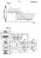
- the ignition timing region where an engine knocks is a region A in Fig. 1, that is, the region above a limiting line a in the normal operating range of the engine.
- the inventors, etc. have confirmed that in the acceleration operation range of the engine or a region B, the borderline region conductive to engine knocking varies abruptly as indicated by a line a 1 and it becomes constant in a high speed region C following the end of the acceleration as shown by a line a 2'
- the ignition timing region conducive to knocking varies abruptly in the acceleration region B.
- the amount of ignition timing retard provided upon occurrence of knocking during the acceleration is insufficient so that as shown by a curve b in Fig. 1 the ignition timing control value is delayed in response to follow the knocking limiting line a 1 and therefore the actual ignition timing control value remains in the region conducive to engine knocking thus causing the engine to knock.
- means for detecting the acceleration condition of an engine is provided so that upon detection of the acceleration condition the amount of retard of ignition timing provided upon occurrence of knocking is increased as compared with that provided during the steady operating condition of the engine, i.e. an operating condition except for the acceleration condition.
- Fig. 2 is a block diagram showing a preferred embodiment of the knock control apparatus according to the invention in which the amount of ignition timing retard provided upon occurrence of knocking is controlled by means of a microcomputer.
- crank angle sensor 4 connected to a microcomputer 12 are a crank angle sensor 4, an air flow sensor 6 and a cooling water temperature sensor 8 which are main sensors.
- the crank angle sensor 4 generates, in synchronism with the rotation of the crankshaft of an engine (not shown), a reference pulse signal shown in (A) of Fig. 4 for each predetermined degrees of rotation, e.g., each 120° of crankshaft rotation and an angular pulse signal for each 1° of crankshaft rotation, for example.
- the knock signal generated from a knock sensor 2 is applied to the microcomputer 12 through a knock signal processing circuit 10.
- the microcomputer 12 includes an input/ output circuit 20 for receiving the output signals of the sensors 4 to 8 and the output signal of the processing circuit 10, an RAM 14, an ROM 16, a CPU 18 and output circuits 22 and 24 for amplifying the output signals from the input/output circuit 20.
- the outputs of the output circuits 22 and 24, i.e., a fuel injection signal and an ignition signal are respectively applied to a fuel injector 26 and an ignition coil 28 which are actuators. Also the output signal of the output circuit 24 is applied to the processing circuit 10.
- the microcomputer 12 In response to the output signals from the sensors 4 to 8 the microcomputer 12 computes the optimum fuel injection timing and ignition timing for the engine and applies as a fuel injection signal and an ignition signal to the injector 26 and the ignition coil 28 through the output circuits 22 and 24, respectively, thereby controlling the engine in an optimum manner.
- This type of engine control system is disclosed for example in U.S. Patent No. 4,276,601.
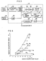
- the knock signal processing circuit 10 is constructed as shown in Fig. 3.
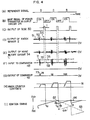
- numeral 32 designates an ac coupling circuit for removing the dc component from the output signal of the knock sensor 2, 34 an ignition noise cutoff circuit including a gate and responsive to the output of a monostable multivibrator 50 to cut off the ignition noise component from the output signal of the ac coupling circuit 32 in synchronism with the ignition timing, 36 a band-pass filter (BPF) for passing the knock signal from the output signal of the ignition noise cutoff circuit 34, 38 an automatic gain control circuit (AGC circuit) responsive to the output of the BPF 36 to control the gain of its own amplifier in proportion to the input signal ratio, 40 a masking circuit responsive to the output of the monostable multivibrator 50 to mask the output of the AGC circuit 38 for a predetermined period of time, 42 a background level (BGL) detecting circuit for averaging the output of the AGC circuit 38 through the masking circuit 40 to obtain an average value of the knock signal, 44 a gain
- circuits 32 to 48 of Fig. 3 are of the known types and their circuit constructions will not be described in detail.
- Shown in (A) of Fig. 4 is the reference pulse signal generated from the crank angle sensor 4 and the ignition timing and the fuel injection timing are determined in accordance with the reference pulse signal.
- Shown in (B) of Fig. 4 is the ignition timing waveform which is the base signal of the power transistor (not shown) in the output circuit 24 whereby the power transistor is turned on when the signal goes to a high level and turned off when the signal goes to a low level.
- the output of the power transistor is applied to the ignition coil 28 and the ignition coil 28 produces a spark when the power transistor is switched from the on state to the off state.
- the output of the power transistor is also applied to the monostable multivibrator 50 of the knock signal processing circuit 10 so that the monostable multivibrator 50 is triggered by the switching of the power transistor from the on state to the off state thereby generating a pulse signal ((C) of Fig. 4) having a predetermined time width T.
- Shown in (D) of Fig. 4 is the output signal of the dc biased knock sensor 2.
- the signal detected by the knock sensor 2 is a signal which swings on both the positive and negative sides of a dc zero level as a reference and the signal is dc biased and generated through a current regulator circuit which is not shown.
- the knock signal includes a knock signal component 52 and an ignition noise component 54 produced by the discharge of the ignition coil 28.
- the output signal of the knock sensor 2 is applied to the ac coupling circuit 32.
- the ac coupling circuit 32 removes the dc bias component contained in the knock signal.
- the ignition noise cutoff circuit 34 is responsive to the output pulse of the monostable multivibrator 50 to cutoff the knock signal during the duration time T of this pulse and thus the output of the ignition noise cutoff circuit 34 has the ignition noise component 54 cutoff as shown in (E) of Fig. 4.
- the output of the ignition noise cutoff circuit 34 is applied to the BPF 36.
- the BPF 36 emphasizes the knock signal component 52 with respect to the background signal 51 ((D) of Fig. 4) and its frequency characteristic is such that its center frequency substantially corresponds to the frequency of the knock signal component.
- the AGC circuit 38 amplifies the output signal of the BPF 36 with a given gain and outputs it.
- the gain of the AGC circuit 38 is controlled by the feedback signal applied thereto from the BGL detecting circuit 42 through the gain control circuit 44. In other words, the gain of the gain control circuit 44 is controlled in inverse proportion to the output signal level of the BGL detecting circuit 42.
- the output signal of the AGC circuit 38 is applied to the masking circuit 40.
- the masking circuit 40 is responsive to the output pulse of the monostable multivibrator 50 to mask the output signal of the AGC circuit 38 during the duration time T of this pulse.
- the output signal of the ignition noise cutoff circuit 34 is passed through the BPF 36, noise appears in the duration T portion of the knock signal subjected to the noise cutoff by the ignition noise cutoff circuit 34 and the masking circuit 40 eliminates this noise.
- the BGL detecting circuit 42 receives the output signal of the masking circuit 40 and detects an average level of the output signal.
- the output signal of the BGL detecting circuit 42 is applied to one input of the comparator 48 and to the gain control circuit 44.
- the gain control circuit 44 amplifies the output signal of the BGL detecting circuit 42 and applies it as a feedback signal to the AGC circuit 38.
- the output of the masking circuit 40 is also amplified by the amplifier 46 and applied to the other input of the comparator 48.
- the comparator 48 compares in level the output signal 56 ((F) of Fig. 4) of the BGL detecting circuit 42 and the output signal 58 of the amplifier 46 to generate the pulse shown in (G) of Fig. 4 each time the level of the latter exceeds the level of the former. In other words, the comparator 48 generates output pulses 73 and 74 when the output signal level 56 of the BGL detecting circuit 42 are exceeded by the peaks (the knock signal components) 71 and 72 of the output signal from the amplifier 46 as shown in (F) of Fig. 4.
- the output pulses of the comparator 48 indicate the occurrence of knocking and they are applied as knock detection pulses to the input/output circuit 20 of the microcomputer 12.
- the knock detection pulses are applied to the RAM 14 from the input/output circuit 20 and are counted by a knock counter in the RAM 14 which is a soft counter. If the count value of the soft counter exceeds a predetermined value while the engine crankshaft rotates through a predetermined angle, the occurrence of knocking is determined and thus the ignition timing is retarded.
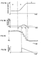
- Fig. 5A shows the relation between the engine operating condition and the intake air quantity such that the intake air quantity Q a increases when the engine moves from a low speed operation indicative region A (corresponding to the region A in Fig. 1) into an acceleration operation indicative region B (corresponding to the region B in Fig. 1) and the intake air quantity Q a remains constant at a high value when the engine comes into a high speed operation indicative region C (corresponding to the region C in Fig. 1).
- the intake air quantity Q a increases suddenly in the region B.
- the amount of change ⁇ Q a of the intake air quantity Q within a given time period increases during the acceleration operation as shown in Fig. 5B.
- the acceleration condition is determined when the amount of change ⁇ Q a equals or exceeds a predetermined value ⁇ Q R , it is possible to easily detect the acceleration condition.
- the ignition timing is retarded a greater number of degrees than the amount of retard during the normal operation thereby preventing the occurrence of knocking.
- the amount of ignition timing retard during the acceleration operation is increased by a predetermined value over the amount of retard during the steady operation irrespective of the count value of the knock counter.
- the microcomputer 12 computes, in response to the input data from the sensors 4 to 8, the required control data for the engine actuators, e.g., the fuel injectors and the ignition coil and applies the data to the actuators through the output circuits 22 and 24 thereby controlling the engine at the desired operating condition.
- the engine actuators e.g., the fuel injectors and the ignition coil
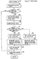
- the REF interrupt is determind first by a step 80 which in turn transfers to a step 82.
- the step 82 reads the count value of the knock counter or soft counter in the RAM 14.
- a step 84 determines whether the count value of the knock counter is equal to or greater than a predetermined value N. If it is, the occurrence of knocking is determined and a transfer is made to a step 86 thereby proceeding to an ignition timing retard processing system. If the count value is less than N, the counted knock detection signals 73 and 74 are determined as noise and a transfer is made to a step 102 thereby clearing the value of the knock counter. In this case, as shown in the time intervals t 1 to t 3 in (I) of Fig. 4, the ignition timing is advanced at a predetermined rate with time and the value of the knock counter is cleared at the time t Z . This advance processing is such that the present ignition timing stored in the RAM 14 is advanced a predetermined angle each time a predetermined time passes. In this embodiment, the count value N is selected 3, for example.
- the step 86 reads ignition timing retard angles 6A and ⁇ B corresponding to the knocking from the ROM 16 and these retard angles ⁇ A and ⁇ B are stored in the RAM 14 by a stp 88.
- 6 B is an ignition timing retard angle used under all the engine operating conditions excluding the acceleration condition
- ⁇ A is an ignition timing retard angle used under the acceleration condition.
- the value of ⁇ A should preferably be selected 2 to 4 times that of ⁇ B .
- a step 90 determines whether the amount of intake air quantity change ⁇ Q a is equal to or greater than the predetermined value ⁇ Q R .
- the value of ⁇ Q a is obtained by subtracting the intake air quantity Q a ' measured in response to the preceeding reference signal and stored in the RAM 14 from the intake air quantity Q a measured by the air flow sensor 6 in response to the current reference signal, as follows: If it is determined that the amount of intake air quantity change ⁇ Q a is equal to or greater than the predetermined value ⁇ Q R , it is decided that the engine is at the acceleration operation and a transfer is made to a step 96. If it is determined that the engine is not accelerating, a transfer is made to a step 92.
- the intake air quantity Q a varies as shown in Fig. 5A so that the value of ⁇ Q a varies as shown in Fig. 5B and the time interval t 1 to t 3 is determined as the acceleration period.
- the step 92 reads from the RAM 14 the retard angle 6 B corresponding to the operating conditions other than the acceleration condition and then a step 94 obtains as a new ignition timing the value resulting from the retardation of the current ignition timing by ⁇ B .
- the next step 100 stores the new ignition timing in the RAM 14 and transfers to the step 102 thereby clearing the value of the knock counter.
- the time of ignition is controlled in accordance with the new ignition timing. In other words, as shown in (I) of Fig. 4, the ignition timing is retarded by the value of 8 B at the time t 3 and thereafter the ignition timing is advanced at a predetermined rate.
- the step 96 reads the ignition timing retard angle 8A from the RAM 14 and the next step 98 obtains as a new ignition timing the value resulting from the retardation of the current ignition timing by the value of ⁇ A .
- the new ignition timing is stored in the RAM 14 by the step 100. Then, similarly a transfer is made to the step 102 and the value of the knock counter is cleared.
- the ignition timing retard characteristic of this first embodiment is shown in Fig. 6.
- the ignition timing retard angle is maintained at the constant value ⁇ B as shown by a straight line 76 in Fig. 6 irrespective of the count value and therefore the ignition timing is maintained substantially constant along a knock limiting line 66 as shown int(I) of Fig. 4. If the engine is at the acceleration operation, the retard angle is maintained at the greater constant value 0A as shown by a straight line 77 irrespective of the count value of the knock counter and consequently the ignition timing is retarded along a knock limiting line 68 as shown in (I) of Fig. 4.
- the retard angle is zero and the ignition timing is advanced gradually.
- the ignition timing retard angle is increased considerably as shown in Fig. 5C and thus the ignition timing control value follows the knock limiting line a 1 shown in Fig. 1 thereby preventing the occurrence of heavy knocking.
- This embodiment is designed so that if the value of the knock counter is eaual to or greater than the predetermined value, the ignition timing retard angle during the acceleration operation is increased over that during the normal operation and also the retard angle is increased with increase in the count value of the knock counter.
- the step 80 determines as REF interrupt and transfers to the step 82.
- the step 82 reads the count value of the knock counter in the RAM 14 which is a soft counter.
- the step 84 determines whether the count value is equal to or greater than the predetermined value N. If it is, the occurrence of knocking is determined and a transfer is made to the step 86 thereby proceeding to the ignition timing retard processing system. If the count value is less than the value N, the counted knock detection signals 73 and 74 are determined as noise and a transfer is made to the step 102 thereby clearing the value of the knock counter.
- the step 86 reads from the map in the ROM 16 the ignition timing retard angles 6A and S B under knocking condition which correspond to the count value and the step 88 stores these retard angles in the RAM 14.
- the ignition timing retard angle is increased as the count value of the knock counter increases and also the retard angle for the acceleration operation is selected 2 to 4 times that for the normal operation.
- the retard angle is controlled in response to the count value of the knock counter and thus the occurrence of heavy knocking is prevented under all the operating conditions, particularly the acceleration condition.
- the third embodiment of the invention when the acceleration condition is detected under the knocking condition, it is considered that thereafter the acceleration condition lasts for a predetermined time and the ignition timing retard angle during this time is increased over that used for the steady operation.
- steps 80 to 88 are the same with their counterparts of the first embodiment.
- a step 89 checks whether the soft timer in the RAM 14 is in operation so that if it is, the knocking under the acceleration condition is determined and a transfer is made to a step 96. If the timer is not in operation, a transfer is made to a step 90 which in turn determines whether the amount of intake air quantity change AQ a is equal to or greater than the predetermined value ⁇ Q Ro .
- the soft timer may for example be a subtraction counter such that a predetermined value is set in the subtraction counter at the time t 2 as shown in Fig. 5D and thereafter the value of the timer is decreased by 1 at intervals of a predetermined time.
- the subtraction counter is performing the subtraction operation the timer is in operation, and the timer is no longer in operation when the contents of the subtraction counter are reduced to zero.
- the operation time of the timer is selected 1 second after its actuation, for example.
- step 95 After the completion of the step 95, a transfer is made to the step 96 so that the retard angle according to the characteristic curve 77 or 79 of Fig. 6 is read and steps 98 to 102 are performed in the same manner as the first embodiment.
- step 90 determines that ⁇ Q a ⁇ ⁇ Q R , it transfers to a step 92 so that the retard angle according to the characteristic curve 76 or 78 of Fig. 6 is read and steps 94, 100 and 102 are performed.
- an amount of retard of ignition timing provided upon occurrence of knocking in an acceleration condition is increased as compared with that provided during the steady operating condition, so that a period during which knocking occurs can be shortened and the occurrence of heavy knocking is prevented even in the acceleration condition.
Landscapes
- Engineering & Computer Science (AREA)
- Signal Processing (AREA)
- Chemical & Material Sciences (AREA)
- Combustion & Propulsion (AREA)
- Mechanical Engineering (AREA)
- General Engineering & Computer Science (AREA)
- Electrical Control Of Ignition Timing (AREA)
Applications Claiming Priority (2)
| Application Number | Priority Date | Filing Date | Title |
|---|---|---|---|
| JP4997/82 | 1982-01-18 | ||
| JP57004997A JPH0650103B2 (ja) | 1982-01-18 | 1982-01-18 | ノツク制御装置 |
Publications (2)
| Publication Number | Publication Date |
|---|---|
| EP0084368A2 true EP0084368A2 (de) | 1983-07-27 |
| EP0084368A3 EP0084368A3 (de) | 1983-09-21 |
Family
ID=11599229
Family Applications (1)
| Application Number | Title | Priority Date | Filing Date |
|---|---|---|---|
| EP83100349A Withdrawn EP0084368A3 (de) | 1982-01-18 | 1983-01-17 | Klopfsteuergerät und Steuermethode für Brennkraftmaschinen |
Country Status (3)
| Country | Link |
|---|---|
| US (1) | US4710881A (de) |
| EP (1) | EP0084368A3 (de) |
| JP (1) | JPH0650103B2 (de) |
Cited By (8)
| Publication number | Priority date | Publication date | Assignee | Title |
|---|---|---|---|---|
| GB2169959A (en) * | 1984-12-28 | 1986-07-23 | Fuji Heavy Ind Ltd | System for controlling the ignition timing of an internal combustion engine |
| EP0191378A1 (de) * | 1985-01-31 | 1986-08-20 | Nissan Motor Co., Ltd. | Zündzeitpunkt-Regelungssystem und Verfahren für Brennkraftmaschine |
| GB2183729A (en) * | 1985-10-22 | 1987-06-10 | Nissan Motor | System and method for controlling ignition timing for an internal combustion engine |
| GB2192228A (en) * | 1986-07-01 | 1988-01-06 | Honda Motor Co Ltd | Apparatus for controlling ignition timing in internal combustion engines |
| GB2193254A (en) * | 1986-07-15 | 1988-02-03 | Audi Ag | Controlling i.c. engine ignition timing |
| WO1990007644A1 (en) * | 1988-12-24 | 1990-07-12 | Robert Bosch Gmbh | Adaptive acceleration knock control |
| EP0392804A3 (de) * | 1989-04-14 | 1991-07-31 | Hitachi, Ltd. | Motorüberwacher, ausgerüstet mit Klopfdetektor |
| WO1991014097A1 (de) * | 1990-03-15 | 1991-09-19 | Robert Bosch Gmbh | Verfahren zur adaptiven klopfregelung einer brennkraftmaschine |
Families Citing this family (19)
| Publication number | Priority date | Publication date | Assignee | Title |
|---|---|---|---|---|
| JPH0811950B2 (ja) * | 1984-07-11 | 1996-02-07 | 日本電装株式会社 | 点火時期制御装置 |
| JPH0444851Y2 (de) * | 1985-10-03 | 1992-10-22 | ||
| KR900006877B1 (ko) * | 1986-12-22 | 1990-09-24 | 미쯔비시덴끼 가부시끼가이샤 | 내연기관의 점화시기 제어장치 |
| JPH07113353B2 (ja) * | 1987-04-30 | 1995-12-06 | 三菱電機株式会社 | 内燃機関の点火時期制御装置 |
| KR880014253A (ko) * | 1987-05-12 | 1988-12-23 | 시끼모리야 | 점화시기 제어장치 |
| KR920000053B1 (ko) * | 1987-05-26 | 1992-01-06 | 미쓰비시전기 주식회사 | 엔진 제어장치 |
| JPS63306002A (ja) * | 1987-06-08 | 1988-12-14 | Dai Ichi Kogyo Seiyaku Co Ltd | 木質成形品の製造方法 |
| JPH0649913Y2 (ja) * | 1987-09-18 | 1994-12-14 | 日産自動車株式会社 | 内燃機関の点火時期制御装置 |
| US4793310A (en) * | 1987-12-03 | 1988-12-27 | Mitsubishi Denki Kabushiki Kaisha | Electronic ignition control apparatus including knocking control |
| US5224044A (en) * | 1988-02-05 | 1993-06-29 | Nissan Motor Company, Limited | System for controlling driving condition of automotive device associated with vehicle slip control system |
| US5027775A (en) * | 1988-02-19 | 1991-07-02 | Mitsubishi Denki K.K. | Apparatus for controlling combustion condition |
| DE3832629A1 (de) * | 1988-09-26 | 1990-04-05 | Daimler Benz Ag | Verfahren zur dynamischen korrektur des zuendzeitpunktes einer brennkraftmaschine |
| US5083278A (en) * | 1989-04-14 | 1992-01-21 | Fuji Jukogyo Kabushiki Kaisha | Knocking detection device for an automotive engine |
| JP2792633B2 (ja) * | 1990-02-09 | 1998-09-03 | 株式会社日立製作所 | 制御装置 |
| EP0443708A2 (de) * | 1990-02-21 | 1991-08-28 | Stresswave Technology Limited | Steuerungsanlage von einer inneren Brennkraftmaschine |
| JPH04224260A (ja) * | 1990-12-26 | 1992-08-13 | Nippondenso Co Ltd | 内燃機関の燃焼状態検出装置 |
| US5608633A (en) * | 1991-07-29 | 1997-03-04 | Nissan Motor Co., Ltd. | System and method for detecting knocking for internal combustion engine |
| JP3167766B2 (ja) * | 1991-11-29 | 2001-05-21 | 本田技研工業株式会社 | 内燃エンジンのノッキング制御装置 |
| US10731621B2 (en) * | 2016-12-21 | 2020-08-04 | Caterpillar Inc. | Ignition system having combustion initiation detection |
Family Cites Families (8)
| Publication number | Priority date | Publication date | Assignee | Title |
|---|---|---|---|---|
| US4002155A (en) * | 1976-01-12 | 1977-01-11 | General Motors Corporation | Engine and engine spark timing control with knock limiting etc. |
| JPS605786B2 (ja) * | 1979-05-25 | 1985-02-14 | 三菱電機株式会社 | 内燃機関の点火時期制御装置 |
| JPS5620763A (en) * | 1979-07-31 | 1981-02-26 | Nissan Motor Co Ltd | Controller for internal combustion engine |
| JPS5669460A (en) * | 1979-11-09 | 1981-06-10 | Hitachi Ltd | Ignition timing controller for internal combustion engine |
| JPS6030474Y2 (ja) * | 1980-11-26 | 1985-09-12 | 日産自動車株式会社 | 内燃機関のノツキング回避装置 |
| JPS5799269A (en) * | 1980-12-11 | 1982-06-19 | Nissan Motor Co Ltd | Ignition timing control device |
| US4428343A (en) * | 1981-11-23 | 1984-01-31 | General Motors Corporation | Tip-in knock eliminating spark timing control |
| US4513716A (en) * | 1981-12-02 | 1985-04-30 | Nippondenso Co., Ltd. | Ignition timing control system with knock control for internal combustion engines |
-
1982
- 1982-01-18 JP JP57004997A patent/JPH0650103B2/ja not_active Expired - Lifetime
-
1983
- 1983-01-17 EP EP83100349A patent/EP0084368A3/de not_active Withdrawn
-
1986
- 1986-05-30 US US06/868,441 patent/US4710881A/en not_active Expired - Fee Related
Cited By (14)
| Publication number | Priority date | Publication date | Assignee | Title |
|---|---|---|---|---|
| GB2169959A (en) * | 1984-12-28 | 1986-07-23 | Fuji Heavy Ind Ltd | System for controlling the ignition timing of an internal combustion engine |
| EP0191378A1 (de) * | 1985-01-31 | 1986-08-20 | Nissan Motor Co., Ltd. | Zündzeitpunkt-Regelungssystem und Verfahren für Brennkraftmaschine |
| US4819603A (en) * | 1985-10-22 | 1989-04-11 | Nissan Motor Company, Limited | System and method for controlling ignition timing for an internal combustion engine |
| GB2183729A (en) * | 1985-10-22 | 1987-06-10 | Nissan Motor | System and method for controlling ignition timing for an internal combustion engine |
| GB2183729B (en) * | 1985-10-22 | 1989-10-11 | Nissan Motor | System and method for controlling ignition timing for an internal combustion engine |
| GB2192228A (en) * | 1986-07-01 | 1988-01-06 | Honda Motor Co Ltd | Apparatus for controlling ignition timing in internal combustion engines |
| GB2192228B (en) * | 1986-07-01 | 1990-05-16 | Honda Motor Co Ltd | Apparatus for controlling ignition timing in internal combustion engine |
| GB2193254A (en) * | 1986-07-15 | 1988-02-03 | Audi Ag | Controlling i.c. engine ignition timing |
| GB2193254B (en) * | 1986-07-15 | 1990-04-04 | Audi Ag | Device for controlling the ignition timing of an internal combustion engine |
| WO1990007644A1 (en) * | 1988-12-24 | 1990-07-12 | Robert Bosch Gmbh | Adaptive acceleration knock control |
| US5265574A (en) * | 1988-12-24 | 1993-11-30 | Robert Bosch Gmbh | Adaptive acceleration knock control |
| EP0392804A3 (de) * | 1989-04-14 | 1991-07-31 | Hitachi, Ltd. | Motorüberwacher, ausgerüstet mit Klopfdetektor |
| WO1991014097A1 (de) * | 1990-03-15 | 1991-09-19 | Robert Bosch Gmbh | Verfahren zur adaptiven klopfregelung einer brennkraftmaschine |
| US5243942A (en) * | 1990-03-15 | 1993-09-14 | Robert Bosch Gmbh | Process for controlling knocking in internal combustion engines |
Also Published As
| Publication number | Publication date |
|---|---|
| JPH0650103B2 (ja) | 1994-06-29 |
| EP0084368A3 (de) | 1983-09-21 |
| US4710881A (en) | 1987-12-01 |
| JPS58122364A (ja) | 1983-07-21 |
Similar Documents
| Publication | Publication Date | Title |
|---|---|---|
| EP0084368A2 (de) | Klopfsteuergerät und Steuermethode für Brennkraftmaschinen | |
| US4344400A (en) | Control device for an internal combustion engine | |
| EP0733891B1 (de) | Vor-Zündungserfassungssystem | |
| US6311672B1 (en) | Device for controlling the knocking of an internal combustion engine | |
| EP0044537A1 (de) | Verfahren zur Steuerung der Kraftstoffinjektion in einer Brennkraftmaschine | |
| CA2037729A1 (en) | Method of controlling an internal combustion engine | |
| EP0096869B1 (de) | Verfahren und Gerät zur Steuerung eines Zündsystems | |
| US4803967A (en) | System for controlling ignition timing of an internal combustion engine | |
| EP0087162A2 (de) | Klopfsteuereinrichtung und Verfahren für eine Brennkraftmaschine | |
| US20010050071A1 (en) | Knock control apparatus for internal-combustion engine | |
| US4385607A (en) | Automobile ignition timing control system | |
| US7753027B2 (en) | Apparatus and method for controlling knock in an internal combustion engine | |
| GB2170327A (en) | Method of controlling fuel injection | |
| US4523567A (en) | Ignition timing control system for internal-combustion engine | |
| US6668798B2 (en) | Apparatus for controlling ignition timing of engine | |
| US4452206A (en) | Ignition timing control system for internal combustion engines | |
| JP2596139B2 (ja) | アルコール混合燃料内燃機関のノッキング制御装置 | |
| US5955664A (en) | Device for detecting a state of combustion in an internal combustion engine | |
| JPH0346667B2 (de) | ||
| JPS6329061A (ja) | 内燃機関の点火時期制御装置 | |
| US5392748A (en) | Ignition timing controlling device for an engine | |
| JPS6122141B2 (de) | ||
| JPS634023B2 (de) | ||
| JP2850583B2 (ja) | 内燃機関の回転速度低下検出装置 | |
| JPH03185270A (ja) | 内燃機関の点火時期制御装置 |
Legal Events
| Date | Code | Title | Description |
|---|---|---|---|
| PUAI | Public reference made under article 153(3) epc to a published international application that has entered the european phase |
Free format text: ORIGINAL CODE: 0009012 |
|
| PUAL | Search report despatched |
Free format text: ORIGINAL CODE: 0009013 |
|
| AK | Designated contracting states |
Designated state(s): CH DE FR GB IT LI NL SE |
|
| AK | Designated contracting states |
Designated state(s): CH DE FR GB IT LI NL SE |
|
| 17P | Request for examination filed |
Effective date: 19830922 |
|
| STAA | Information on the status of an ep patent application or granted ep patent |
Free format text: STATUS: THE APPLICATION HAS BEEN WITHDRAWN |
|
| 18W | Application withdrawn |
Withdrawal date: 19850920 |
|
| RIN1 | Information on inventor provided before grant (corrected) |
Inventor name: SUGIURA, NOBORU Inventor name: MOURI, YASUNORI |