EP0084458A2 - Mit Ultraschall arbeitende Flüssigkeitszerstäubungsvorrichtung - Google Patents
Mit Ultraschall arbeitende Flüssigkeitszerstäubungsvorrichtung Download PDFInfo
- Publication number
- EP0084458A2 EP0084458A2 EP83300242A EP83300242A EP0084458A2 EP 0084458 A2 EP0084458 A2 EP 0084458A2 EP 83300242 A EP83300242 A EP 83300242A EP 83300242 A EP83300242 A EP 83300242A EP 0084458 A2 EP0084458 A2 EP 0084458A2
- Authority
- EP
- European Patent Office
- Prior art keywords
- vibrating member
- ejecting apparatus
- transducer
- liquid ejecting
- ring
- Prior art date
- Legal status (The legal status is an assumption and is not a legal conclusion. Google has not performed a legal analysis and makes no representation as to the accuracy of the status listed.)
- Granted
Links
Images




Classifications
-
- B—PERFORMING OPERATIONS; TRANSPORTING
- B05—SPRAYING OR ATOMISING IN GENERAL; APPLYING FLUENT MATERIALS TO SURFACES, IN GENERAL
- B05B—SPRAYING APPARATUS; ATOMISING APPARATUS; NOZZLES
- B05B17/00—Apparatus for spraying or atomising liquids or other fluent materials, not covered by the preceding groups
- B05B17/04—Apparatus for spraying or atomising liquids or other fluent materials, not covered by the preceding groups operating with special methods
- B05B17/06—Apparatus for spraying or atomising liquids or other fluent materials, not covered by the preceding groups operating with special methods using ultrasonic or other kinds of vibrations
- B05B17/0607—Apparatus for spraying or atomising liquids or other fluent materials, not covered by the preceding groups operating with special methods using ultrasonic or other kinds of vibrations generated by electrical means, e.g. piezoelectric transducers
- B05B17/0638—Apparatus for spraying or atomising liquids or other fluent materials, not covered by the preceding groups operating with special methods using ultrasonic or other kinds of vibrations generated by electrical means, e.g. piezoelectric transducers spray being produced by discharging the liquid or other fluent material through a plate comprising a plurality of orifices
- B05B17/0646—Vibrating plates, i.e. plates being directly subjected to the vibrations, e.g. having a piezoelectric transducer attached thereto
-
- B—PERFORMING OPERATIONS; TRANSPORTING
- B05—SPRAYING OR ATOMISING IN GENERAL; APPLYING FLUENT MATERIALS TO SURFACES, IN GENERAL
- B05B—SPRAYING APPARATUS; ATOMISING APPARATUS; NOZZLES
- B05B17/00—Apparatus for spraying or atomising liquids or other fluent materials, not covered by the preceding groups
- B05B17/04—Apparatus for spraying or atomising liquids or other fluent materials, not covered by the preceding groups operating with special methods
- B05B17/06—Apparatus for spraying or atomising liquids or other fluent materials, not covered by the preceding groups operating with special methods using ultrasonic or other kinds of vibrations
- B05B17/0607—Apparatus for spraying or atomising liquids or other fluent materials, not covered by the preceding groups operating with special methods using ultrasonic or other kinds of vibrations generated by electrical means, e.g. piezoelectric transducers
- B05B17/0653—Details
- B05B17/0669—Excitation frequencies
-
- B—PERFORMING OPERATIONS; TRANSPORTING
- B41—PRINTING; LINING MACHINES; TYPEWRITERS; STAMPS
- B41J—TYPEWRITERS; SELECTIVE PRINTING MECHANISMS, i.e. MECHANISMS PRINTING OTHERWISE THAN FROM A FORME; CORRECTION OF TYPOGRAPHICAL ERRORS
- B41J2/00—Typewriters or selective printing mechanisms characterised by the printing or marking process for which they are designed
- B41J2/005—Typewriters or selective printing mechanisms characterised by the printing or marking process for which they are designed characterised by bringing liquid or particles selectively into contact with a printing material
- B41J2/01—Ink jet
- B41J2/015—Ink jet characterised by the jet generation process
- B41J2/02—Ink jet characterised by the jet generation process generating a continuous ink jet
- B41J2/025—Ink jet characterised by the jet generation process generating a continuous ink jet by vibration
-
- F—MECHANICAL ENGINEERING; LIGHTING; HEATING; WEAPONS; BLASTING
- F23—COMBUSTION APPARATUS; COMBUSTION PROCESSES
- F23D—BURNERS
- F23D11/00—Burners using a direct spraying action of liquid droplets or vaporised liquid into the combustion space
- F23D11/34—Burners using a direct spraying action of liquid droplets or vaporised liquid into the combustion space by ultrasonic means
- F23D11/345—Burners using a direct spraying action of liquid droplets or vaporised liquid into the combustion space by ultrasonic means with vibrating atomiser surfaces
-
- B—PERFORMING OPERATIONS; TRANSPORTING
- B41—PRINTING; LINING MACHINES; TYPEWRITERS; STAMPS
- B41J—TYPEWRITERS; SELECTIVE PRINTING MECHANISMS, i.e. MECHANISMS PRINTING OTHERWISE THAN FROM A FORME; CORRECTION OF TYPOGRAPHICAL ERRORS
- B41J2202/00—Embodiments of or processes related to ink-jet or thermal heads
- B41J2202/01—Embodiments of or processes related to ink-jet heads
- B41J2202/15—Moving nozzle or nozzle plate
Definitions
- the present invention relates to an ultrasonic liquid ejecting apparatus for discharging liquid in the form of diverging streams or a single jet stream depending on various applications in which the apparatus is used.
- the invention is useful for universal applications including fuel burners and printers.
- a piezoelectric oscillating system for effecting atomization of liquids is described in United States Patent 3,738,.574.
- Such a piezoelectric oscillating system comprises a piezoelectric transducer mechanically coupled by a frustum to a vibrator plate for inducing bending vibrations therein, a fluid tank and a pump for delivering fluid to the vibrating plate which is disposed at an oblique angle with respect to the force of gravity above the tank.
- a wick is provided to aid in diverting excess liquid from the plate to the tank.
- the frustum serves as a means for amplifying the energy generated by the transducer.
- the frustrum needs to be machined to a high degree of precision and maintained in a correct position with respect to a conduit through which the pumped fluid is dropped on the vibrator plate and the amount of fluid to be delivered from the pump must be accurately controlled.
- Further disadvantages are that the system is bulky and expensive and requires high power for atomizing a given amount of liquid. In some instances 10 watts of power is required for atomizing liquid of 20 cubic centimeters per minute, and yet the droplet size is not uniform.
- United States Patent 3,683,212 discloses a pulsed liquid ejection system comprising a conduit which is connected at one end to a liquid containing reservoir and terminates at the other end in a small orifice.
- a tubular transducer surrounds the conduit for generating stress therein to expel a small quantity of liquid through the orifice at high speeds in the form of a stream to a writing surface.
- United States Patent 3,747,120 discloses a liquid ejection apparatus having an inner and an outer liquid chamber separated by a dividing plate having a connecting channel therein.
- a piezoelectric transducer is provided rearward of the apparatus to couple to the liquid in the inner chamber to generate rapid pressure rises therein to expel a small quantity of liquid in the outer chamber through a nozzle which is coaxial to the connecting channel.
- Copending European Patent Application No. 82305448.1 discloses a liquid ejecting device comprising a housing defining a liquid chamber, a ring-shaped piezoelectric transducer and a vibrating member secured to the transducer in pressure transmitting relationship with the liquid in the chamber, and the aim of the present invention is to improve the device of that application.
- the ultrasonic liquid ejecting apparatus of the invention comprises a housing including a chamber for holding liquid therein having an intake port connected to a liquid supply container, and a vibrator system including a kann vibrating member secured to the housing in pressure transmitting relation with the liquid in the chamber and having at least one nozzle opening therein and a piezo-electric transducer secured to the vibrating member for inducing therein a displacement to discharge a small quantity of liquid through the nozzle opening.
- Means are provided for exciting the transducer at a frequency corresponding to the resonant frequency of the vibrator system. The operating efficiency of the liquid ejecting device is maximized by the resonant vibration of the vibrator system.
- the piezoelectric transducer is in the form of a ring and electrically polarized in the direction of thickness, the nozzle opening being located coaxially with the aperture of the ring so that the ring-shaped transducer and an outer area of the vibrating member form an outer part of the vibrator system and the inner area of the vibrating member located inside the aperture forms an inner part of the vibrator system, the mechanical impedance of the outer part substantially equals the mechanical impedance of the inner part.
- the liquid ejection unit is particularly suitable for use in atomizing fuel or the like and comprises a metallic body 11 formed with a liquid chamber 12 having a diameter of 5 to 15 milimeters and a depth of 1 to 5 millimeters.
- An axially vibrating nozzle disc 13 preferably formed of a thin metal film having a thickness of 30 to 100 micrometers, is secured to the perimeter of chamber 12 front wall of body 11.
- a ring-shaped piezoelectric transducer 14 leaving the center portion of the nozzle disc 13 to be exposed to the outside.
- the transducer 14 is of a piezoelectric ceramic which is polarized in the direction of thickness so that upon application of a potential to the electrodes 15 and 16 vibration occurs therein in radial directions as illustrated in Fig. 2.
- the transducer 14 has an outer diameter of 5 to 15 milimeters, an inner diameter of 2 to 8 milimeters and a thickness of 0.5 to 2 milimeters.
- the center portion of the nozzle plate 13 is curved outward as shown at 13a and provided with a plurality of nozzle openings 13b each having a diameter of 30 to 100 micrometers.
- the transducer 14 is provided with a pair of film electrodes 15 and 16 on opposite surfaces thereof.
- the chamber 12 is in communication with a liquid supply conduit 17 which is in turn connected to a liquid supply source and is connected by a conduit 18 to an air chamber the function of which will be described later. Connections are made by wires 19a and 19b from a circuit which will be described later to the electrodes of the piezoelectric transducer 14.
- the body 11 is secured to a suitable support 20 by a screw 21.
- the liquid ejection unit 10 is mounted.in a fuel burner 30 as illustrated in Fig. 3.
- the burner 30 comprises a first chamber 31 and a second chamber 32.
- Fans 33 and 34 respectively located in the chambers 31 and 32 are coupled by a shaft 35 to a fan motor 36.
- the first chamber 31 is open at the right end to the outside through an orifice 37 and an air inlet opening 38 to draw in air as indicated by arror 39 so that the pressure in chamber 31 is reduced below the atmospheric pressure and the downstream end of the chamber 31 is in communication with a combustion chamber 40.
- the second chamber 32 is connected at one end by a conduit 41 to the first chamber 31 and connected at the other end by the conduit 18 to the liquid ejection unit 10.
- a fuel tank 42 supplies fuel to a leveler 43 which serves to maintain the fuel supplied to the unit 10 under a constant pressure regardless of the volume of fuel in the tank 42.
- the fuel in the conduit 17 stands at a level slightly below the unit 10.
- the fan 33 causes the upstream end of first chamber 31 to drop to a subatmospheric presssure of typically -10 mmAg and the fan 34 forces air into the upstream end of first chamber 31 through conduit 41 while at the same time causing a pressure difference of typically -30 mmAg to occur between the right and left end of second chamber 32. Therefore, the static pressure in conduit 18 drops to -40 mmAg drawing the liquid in conduit 17 upward through the chamber 12 of unit 10 into the conduit 18 and the head of the liquid therein is maintained thereafter.
- the chamber 12 is thus filled with liquid which is maintained at a static pressure equal to or lower than the static pressure in front of nozzle disc 13.
- the static pressure of the liquid is kept at -10 mmAg to -20 mmAg lower than the pressure in front of the nozzle disc.
- an ignitor 44 Located forwardly of the unit 10 is an ignitor 44 to cause ignition of fuel droplets. Complete combustion occurs in the combustion chamber 40 by mixture with air introduced through the first chamber 31.
- nozzle disc 13 Upon application of a high frequency burst signal to the transducer 14 vibration occurs in radial directions therein to cause nozzle disc 13 to deflect rearward as shown at 13' to generate a pressure rise in the liquid causing a small amount of liquid near the nozzle openings to be discharged therethrough in the form of diverging streams of droplets at high speeds as indicated at 61.
- the nozzle disc 13 is then deflected forward as shown at 13" to produce a pressure decrease until the pressure in liquid balances against the surface tension at the nozzle openings 13b with the result that liquid is sucked into the chamber 12 through conduit 17.
- Most of the energy applied to the transducer 14 is converted to an axial displacement of the nozzle disc 13 having a sharp increase at the center portion of disc 13 as indicated by a curve 60 compared with the displacement at the edge thereof.
- the ejection unit can be operated at such a high frequency in the range of 30 kHz to 100 kHz described above. If the liquid contains a large quantity of dissolved air cavitation would occur when the nozzle disc 13 is displaced forward. Since the vibration occurs at the forward end of the liquid chamber 12, the pressure rise tends to concentrate in the vicinity of nozzle openings 13b and bubbles tend to move away from the pressure concentrated area, so that the liquid ejecting device of the invention is unaffected by bubbles even if air is dissolved in the liquid chamber 12.
- the conduit 18 also serves as a means for venting such bubbles to the outside. This arrangement is particularly useful when liquid such as kerosene is used since it contains a large amount of dissolved air.
- Figs. 5a-5c and 5d-5f While the piezoelectric transducer 14 itself vibrates in radial directions as shown in Fig. 2, such radial vibration is converted into an axial displacement since the nozzle disc 13 and transducer 14 are considered to form a bimorph system which generates two sets of different vibrational mode patterns as illustrated in Figs. 5a-5c and 5d-5f.
- the mode pattern shown in Fig. 5a is primarily generated by the outer part of the bimorph system which is formed by the transducer 14 and the outer area of the nozzle plate 13 when the system is excited at a frequency corresponding to the resonant frequency fr 2l of the outer part of the bimorph system.
- the mode pattern shown in Fig. 5d is primarily generated by the inner part of the bimorph system formed by the area of the nozzle plate 13 inside of the aperture of the transducer 14 when the system is excited at a frequency corresponding to the resonant frequency fr 11 of the inner part of the bimorph system.
- the mode patterns of Figs. 5e and 5f are generated when the system is excited at frequencies corresponding to the second and third harmonics fr l2 and fr13 of the inner part of the system.
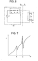
- Fig. 6 shows the equivalent circuit of the bimorph system as comprising two series resonance circuits 30 and 31 coupled in series to a source of electromotive force F which represents the driving power applied to the transducer 14.
- the resonance circuit 30 corresponds to the outer part of the bimorph system and is formed by a resistor R 1 , an inductor L 1 and a capacitor C 1 and the resonance circuit 31 corresponds to the inner part of the system and is formed by a resistor R 2 , an inductor L 2 and a capacitor C 2 .
- Fig. 7 is a graphic representation of the current generated in the transducer 14 which was measured as a function of the operating frequency fo. It is seen that the current has lower and higher peak values at low and high frequencies f 1 and f 2 , respectively. It is most preferred that the outer and inner parts of the bimorph system are respectively dimensioned so that the fundamental resonant frequency of the outer part substantially corresponds to the second harmonic of the resonant frequency of the inner part. Experiments show that the higher peak at frequency f 2 , typically 50 kHz, is obtained when fr 21 nearly equals fr 12 . Thus, the operating frequency is in a range of 45 kHz to 55 kHz.
- liquid ejection devices having transducers of a different outer diameter were experimentally constructed and the amount of axial displacement at the center of nozzle 13b were measured by exciting the transducer 14 at a given constant frequency.
- the axial displacement d is at maximum when the transducer 14 has a diameter D 2 .
- the axial displacement d was measured by varying the operating frequency fo.
- Fig. 8b shows that the axial displacement reaches a maximum when the operating frequency coincides with f 2 .
- Fig. 9 is an illustration of a modified form of the present invention which allows a large amount of fluid to be ejected.
- the liquid ejection device 10 of,Fig. 9 comprises a nozzle plate 113 having a plurality of groups of nozzle openings 113a, the nozzle openings of each group being located in positions substantially corresponding to antinodes of the vibration indicated by a broken lines 120.
- the transducer 114 has an aperture of a dimension sufficient to cause the inner part of the nozzle plate 113 to vibrate in the mode of second harmonic (Fig. 5e) at frequency fr12.
- the liquid ejection devices 10 of the invention of Figs. 1 and 9 are particularly useful for application in kerosene heaters due to the fact that kerosene contains a substantial amount of dissolved air which tends to produce cavitation.
- kerosene contains a substantial amount of dissolved air which tends to produce cavitation.
- the bimorph vibration system at the forward end of the device, only a small amount of kerosene located adjacent the nozzle area is needed to be displaced for ejection.
- the presence of bubbles, if any, in the liquid chamber does not affect the operation of the device.
- the device further requires a small amount of power for operation.
- the device 10 is modified in a manner as shown in Fig. 10 so that the nozzle disc 114 has a single nozzle 114a for discharging a single stream of ink jet onto a writing surface such as recording sheet in a printer or facsimile.
- the liquid chamber 112 is in communication with an ink supply 200 which may be located below the device 10 and with a suction pump 201 which sucks the ink to a level indicated at 202 higher than the liquid chamber.
- Fig. 11 is a further modification of the liquid ejection device in which a single-nozzle bimorph vibrator system formed by elements 213 and 214 is snapped into an elastic body 210 formed typically of rubber.
- Fig. 12 illustrates an electrical circuit that drives the transducer 14 for fuel burner applications.
- Emitter-grounded transistors 91 and 92 are cross-coupled to form a variable frequency multivibrator oscillator 51.
- a potentiometer 94 through which the base of transistor 91 is connected to the base of transistor 92 serves as a manual control device for setting the duty ratio of the multivibrator to determine the amount of liquid to be ejected.
- the wiper terminal of potentiometer 94 is connected to a voltage stabilized DC power source 90.
- the collectors of transistors 91, 92 are connected together by resistors 95 and 96 to the DC power source 90.
- a high frequency unipolar pulse generator 52 comprising a transistor 100 whose collector is connected to a junction between an inductor 101 and a capacitor 102 and whose base is connected through resistors 103, 104 and through the collector-emitter path of transistor 99 to the DC power source so that transistor 100 is switched on and off in response to the on-off time of transistor 99.
- the collector of transistor 100 is connected by a feedback circuit including the primary winding of a transformer 105, capacitor 106 and resistor 103 to the base thereof.
- the secondary winding of transformer 105 is connected to the piezoelectric transducer 14 of unit 10.
- An ultrasonic frequency signal (30 kHz to 100 kHz) is generated in the oscillator 52 during periods when the transistor 99 is turned on.
- the circuit of Fig. 12 can be readily modified by replacing the variable frequency oscillator 51 with a similar circuit
Landscapes
- Engineering & Computer Science (AREA)
- Chemical & Material Sciences (AREA)
- Combustion & Propulsion (AREA)
- Mechanical Engineering (AREA)
- General Engineering & Computer Science (AREA)
- Special Spraying Apparatus (AREA)
Applications Claiming Priority (6)
| Application Number | Priority Date | Filing Date | Title |
|---|---|---|---|
| JP57006284A JPS58122073A (ja) | 1982-01-18 | 1982-01-18 | 霧化装置 |
| JP6284/82 | 1982-01-18 | ||
| JP57020030A JPS58137462A (ja) | 1982-02-10 | 1982-02-10 | 霧化装置 |
| JP20030/82 | 1982-02-10 | ||
| JP57107901A JPS59354A (ja) | 1982-06-23 | 1982-06-23 | 霧化装置 |
| JP107901/82 | 1982-06-23 |
Publications (3)
| Publication Number | Publication Date |
|---|---|
| EP0084458A2 true EP0084458A2 (de) | 1983-07-27 |
| EP0084458A3 EP0084458A3 (en) | 1984-05-23 |
| EP0084458B1 EP0084458B1 (de) | 1986-12-03 |
Family
ID=27277098
Family Applications (1)
| Application Number | Title | Priority Date | Filing Date |
|---|---|---|---|
| EP83300242A Expired EP0084458B1 (de) | 1982-01-18 | 1983-01-18 | Mit Ultraschall arbeitende Flüssigkeitszerstäubungsvorrichtung |
Country Status (5)
| Country | Link |
|---|---|
| US (1) | US4605167A (de) |
| EP (1) | EP0084458B1 (de) |
| AU (1) | AU540267B2 (de) |
| CA (1) | CA1206996A (de) |
| DE (1) | DE3368115D1 (de) |
Cited By (17)
| Publication number | Priority date | Publication date | Assignee | Title |
|---|---|---|---|---|
| EP0099730B1 (de) * | 1982-07-14 | 1987-09-09 | Matsushita Electric Industrial Co., Ltd. | Ultraschallzerstäuber und Verfahren zu dessen Herstellung |
| WO1995003179A1 (en) * | 1993-07-19 | 1995-02-02 | Océ-Nederland B.V. | An ink-jet array |
| EP0648606A3 (de) * | 1993-10-19 | 1995-08-30 | Tektronix Inc | Auf Abruf arbeitender Tintenstrahlkopf und Verfahren. |
| EP0681873A1 (de) * | 1994-03-22 | 1995-11-15 | Siemens Aktiengesellschaft | Vorrichtung zur Zumessung und Zerstäubung von Fluiden |
| GB2291605A (en) * | 1991-11-12 | 1996-01-31 | Medix Ltd | A nebuliser and nebuliser control system |
| US5518179A (en) * | 1991-12-04 | 1996-05-21 | The Technology Partnership Limited | Fluid droplets production apparatus and method |
| WO1997029851A1 (en) * | 1996-02-13 | 1997-08-21 | The Technology Partnership Plc | Liquid supply apparatus |
| RU2131087C1 (ru) * | 1998-06-22 | 1999-05-27 | Общество ограниченной ответственности "Энерго-аудит" | Гидродинамический кавитационный и ультразвуковой преобразователь топлива |
| US6062212A (en) * | 1992-11-04 | 2000-05-16 | Bespak Plc | Dispensing apparatus |
| WO2000033972A1 (en) * | 1998-12-10 | 2000-06-15 | The Technology Parternership Plc | Switchable spray generator and method of operation |
| US6212936B1 (en) | 1997-09-01 | 2001-04-10 | Fresenius Ag | Ultrasonic transmitter particularly for an air bubble detector |
| DE102004016985A1 (de) * | 2004-04-07 | 2005-10-27 | Pari GmbH Spezialisten für effektive Inhalation | Aerosolerzeugungsvorrichtung und Inhalationsvorrichtung damit |
| EP2021131A4 (de) * | 2005-05-23 | 2009-07-22 | Biosonic Australia Pty Ltd | Vorrichtung zur zerstäubung und flüssigkeitsfiltration |
| EP2249970A4 (de) * | 2008-02-29 | 2016-07-06 | Microdose Therapeutx Inc | Verfahren und vorrichtung zum antreiben eines wandlers einer inhalationsvorrichtung |
| WO2021180772A1 (en) * | 2020-03-11 | 2021-09-16 | Philip Morris Products S.A. | Aerosol-generating device and system |
| WO2023215389A1 (en) * | 2022-05-03 | 2023-11-09 | Pneuma Respiratory, Inc. | Small active area plate ejector for droplet delivery device |
| US12161795B2 (en) | 2022-07-18 | 2024-12-10 | Pneuma Respiratory, Inc. | Small step size and high resolution aerosol generation system and method |
Families Citing this family (119)
| Publication number | Priority date | Publication date | Assignee | Title |
|---|---|---|---|---|
| CH678099A5 (de) * | 1988-11-17 | 1991-07-31 | Basten Maria Sibylle | |
| US5152456A (en) * | 1989-12-12 | 1992-10-06 | Bespak, Plc | Dispensing apparatus having a perforate outlet member and a vibrating device |
| US6540154B1 (en) | 1991-04-24 | 2003-04-01 | Aerogen, Inc. | Systems and methods for controlling fluid feed to an aerosol generator |
| US7628339B2 (en) * | 1991-04-24 | 2009-12-08 | Novartis Pharma Ag | Systems and methods for controlling fluid feed to an aerosol generator |
| US5938117A (en) * | 1991-04-24 | 1999-08-17 | Aerogen, Inc. | Methods and apparatus for dispensing liquids as an atomized spray |
| US6629646B1 (en) * | 1991-04-24 | 2003-10-07 | Aerogen, Inc. | Droplet ejector with oscillating tapered aperture |
| WO1993001404A1 (en) * | 1991-07-08 | 1993-01-21 | Yehuda Ivri | Ultrasonic fluid ejector |
| US5666141A (en) * | 1993-07-13 | 1997-09-09 | Sharp Kabushiki Kaisha | Ink jet head and a method of manufacturing thereof |
| GB9412669D0 (en) * | 1994-06-23 | 1994-08-10 | The Technology Partnership Plc | Liquid spray apparatus |
| JPH07285221A (ja) * | 1994-04-19 | 1995-10-31 | Sharp Corp | インクジェットヘッド |
| US5586723A (en) * | 1994-10-07 | 1996-12-24 | Spraying Systems Co. | Liquid spray nozzle with liquid injector/extractor |
| FR2726603B1 (fr) * | 1994-11-09 | 1996-12-13 | Snecma | Dispositif de controle actif des instabilites de combustion et de decokefaction d'un injecteur de carburant |
| US6014970A (en) * | 1998-06-11 | 2000-01-18 | Aerogen, Inc. | Methods and apparatus for storing chemical compounds in a portable inhaler |
| US6205999B1 (en) | 1995-04-05 | 2001-03-27 | Aerogen, Inc. | Methods and apparatus for storing chemical compounds in a portable inhaler |
| US6085740A (en) | 1996-02-21 | 2000-07-11 | Aerogen, Inc. | Liquid dispensing apparatus and methods |
| US5758637A (en) | 1995-08-31 | 1998-06-02 | Aerogen, Inc. | Liquid dispensing apparatus and methods |
| US6782886B2 (en) | 1995-04-05 | 2004-08-31 | Aerogen, Inc. | Metering pumps for an aerosolizer |
| US5828394A (en) * | 1995-09-20 | 1998-10-27 | The Board Of Trustees Of The Leland Stanford Junior University | Fluid drop ejector and method |
| JP3516284B2 (ja) * | 1995-12-21 | 2004-04-05 | 富士写真フイルム株式会社 | 液体噴射装置 |
| US5917521A (en) * | 1996-02-26 | 1999-06-29 | Fuji Xerox Co.,Ltd. | Ink jet recording apparatus and method for jetting an ink droplet from a free surface of an ink material using vibrational energy |
| JPH10307381A (ja) * | 1997-03-04 | 1998-11-17 | Fuji Photo Film Co Ltd | 液体噴射装置及び液体噴射装置の製造方法 |
| US6247525B1 (en) | 1997-03-20 | 2001-06-19 | Georgia Tech Research Corporation | Vibration induced atomizers |
| HUP9800508A1 (hu) * | 1998-03-09 | 2000-02-28 | György Hegedűs | Szerkezet vibrációs folyadékadagoláshoz |
| GB2335628B (en) * | 1998-03-19 | 2001-09-05 | The Technology Partnership Plc | Droplet generator and method of operating a droplet generator |
| GB9808182D0 (en) * | 1998-04-17 | 1998-06-17 | The Technology Partnership Plc | Liquid projection apparatus |
| EP1005916A1 (de) * | 1998-12-01 | 2000-06-07 | Microflow Engineering SA | Inhalator mit Ultraschallzerstäuber dessen Düsenöffnungen den Amplitudenmaxima eines stehenden Wellenmusters überlagert sind |
| ES2149748T3 (es) * | 1998-12-01 | 2007-06-16 | Microflow Engineering Sa | Inhalador con nebulizador de ondas ultrasonicas que presenta unas aberturas de boquilla superpuestas sobre las crestas de un patron de onda estacionaria. |
| GB9903433D0 (en) | 1999-02-15 | 1999-04-07 | The Technology Partnership Plc | Droplet generation method and device |
| DE19938055A1 (de) * | 1999-08-12 | 2001-03-15 | Fraunhofer Ges Forschung | Aktorbauglied für einen Mikrozerstäuber und Verfahren zu seiner Herstellung |
| US6235177B1 (en) | 1999-09-09 | 2001-05-22 | Aerogen, Inc. | Method for the construction of an aperture plate for dispensing liquid droplets |
| GB0000368D0 (en) * | 2000-01-07 | 2000-03-01 | Xaar Technology Ltd | Droplet deposition apparatus |
| US8336545B2 (en) | 2000-05-05 | 2012-12-25 | Novartis Pharma Ag | Methods and systems for operating an aerosol generator |
| US6948491B2 (en) | 2001-03-20 | 2005-09-27 | Aerogen, Inc. | Convertible fluid feed system with comformable reservoir and methods |
| MXPA02010884A (es) | 2000-05-05 | 2003-03-27 | Aerogen Ireland Ltd | Aparato y metodo para el suministro de medicamentos al sistema respiratorio. |
| US7600511B2 (en) | 2001-11-01 | 2009-10-13 | Novartis Pharma Ag | Apparatus and methods for delivery of medicament to a respiratory system |
| US7971588B2 (en) | 2000-05-05 | 2011-07-05 | Novartis Ag | Methods and systems for operating an aerosol generator |
| US7100600B2 (en) | 2001-03-20 | 2006-09-05 | Aerogen, Inc. | Fluid filled ampoules and methods for their use in aerosolizers |
| US6341732B1 (en) * | 2000-06-19 | 2002-01-29 | S. C. Johnson & Son, Inc. | Method and apparatus for maintaining control of liquid flow in a vibratory atomizing device |
| US6543443B1 (en) | 2000-07-12 | 2003-04-08 | Aerogen, Inc. | Methods and devices for nebulizing fluids |
| US6474785B1 (en) | 2000-09-05 | 2002-11-05 | Hewlett-Packard Company | Flextensional transducer and method for fabrication of a flextensional transducer |
| US6546927B2 (en) | 2001-03-13 | 2003-04-15 | Aerogen, Inc. | Methods and apparatus for controlling piezoelectric vibration |
| US6550472B2 (en) | 2001-03-16 | 2003-04-22 | Aerogen, Inc. | Devices and methods for nebulizing fluids using flow directors |
| US6474787B2 (en) | 2001-03-21 | 2002-11-05 | Hewlett-Packard Company | Flextensional transducer |
| US6540339B2 (en) | 2001-03-21 | 2003-04-01 | Hewlett-Packard Company | Flextensional transducer assembly including array of flextensional transducers |
| US6554201B2 (en) | 2001-05-02 | 2003-04-29 | Aerogen, Inc. | Insert molded aerosol generator and methods |
| US6732944B2 (en) | 2001-05-02 | 2004-05-11 | Aerogen, Inc. | Base isolated nebulizing device and methods |
| US6550691B2 (en) | 2001-05-22 | 2003-04-22 | Steve Pence | Reagent dispenser head |
| US6428140B1 (en) | 2001-09-28 | 2002-08-06 | Hewlett-Packard Company | Restriction within fluid cavity of fluid drop ejector |
| US6685302B2 (en) | 2001-10-31 | 2004-02-03 | Hewlett-Packard Development Company, L.P. | Flextensional transducer and method of forming a flextensional transducer |
| US7360536B2 (en) | 2002-01-07 | 2008-04-22 | Aerogen, Inc. | Devices and methods for nebulizing fluids for inhalation |
| US7677467B2 (en) | 2002-01-07 | 2010-03-16 | Novartis Pharma Ag | Methods and devices for aerosolizing medicament |
| WO2003059424A1 (en) | 2002-01-15 | 2003-07-24 | Aerogen, Inc. | Methods and systems for operating an aerosol generator |
| WO2003068412A1 (en) * | 2002-02-11 | 2003-08-21 | Sara Lee/De N.V. | Liquid spray-head, apparatus comprising a liquid spray-head and container therefore |
| US7387265B2 (en) * | 2002-03-05 | 2008-06-17 | Microwflow Engineering Sa | Method and system for ambient air scenting and disinfecting based on flexible, autonomous liquid atomizer cartridges and an intelligent networking thereof |
| US6802460B2 (en) * | 2002-03-05 | 2004-10-12 | Microflow Engineering Sa | Method and system for ambient air scenting and disinfecting based on flexible, autonomous liquid atomizer cartridges and an intelligent networking thereof |
| US6789741B2 (en) * | 2002-03-27 | 2004-09-14 | S. C. Johnson & Son, Inc. | Method and apparatus for atomizing liquids having minimal droplet size |
| ES2572770T3 (es) | 2002-05-20 | 2016-06-02 | Novartis Ag | Aparato para proporcionar pulverización para tratamiento médico y métodos |
| TW532236U (en) * | 2002-06-25 | 2003-05-11 | Wen-Bin Chen | Modular water mist generating device |
| CA2526362C (en) | 2003-05-20 | 2012-10-09 | James F. Collins | Ophthalmic drug delivery system |
| US8545463B2 (en) | 2003-05-20 | 2013-10-01 | Optimyst Systems Inc. | Ophthalmic fluid reservoir assembly for use with an ophthalmic fluid delivery device |
| US8616195B2 (en) | 2003-07-18 | 2013-12-31 | Novartis Ag | Nebuliser for the production of aerosolized medication |
| WO2005088655A1 (en) * | 2004-03-12 | 2005-09-22 | The Provost Fellows And Scholars Of The College Of The Holy And Undivided Trinity Of Queen Elizabeth Near Dublin | A magnetoresistive medium |
| US7946291B2 (en) | 2004-04-20 | 2011-05-24 | Novartis Ag | Ventilation systems and methods employing aerosol generators |
| US7267121B2 (en) | 2004-04-20 | 2007-09-11 | Aerogen, Inc. | Aerosol delivery apparatus and method for pressure-assisted breathing systems |
| US7290541B2 (en) | 2004-04-20 | 2007-11-06 | Aerogen, Inc. | Aerosol delivery apparatus and method for pressure-assisted breathing systems |
| US7775459B2 (en) * | 2004-06-17 | 2010-08-17 | S.C. Johnson & Son, Inc. | Liquid atomizing device with reduced settling of atomized liquid droplets |
| DE102005005540B4 (de) * | 2005-02-07 | 2007-10-04 | Pari GmbH Spezialisten für effektive Inhalation | In verschiedenen Moden ansteuerbare Inhalationstherapievorrichtung |
| DE102005006374B3 (de) | 2005-02-11 | 2006-07-20 | Pari GmbH Spezialisten für effektive Inhalation | Aerosolerzeugungsvorrichtung und Inhalationstherapiegerät mit einer derartigen Vorrichtung |
| DE102005006375B4 (de) * | 2005-02-11 | 2007-10-11 | Pari GmbH Spezialisten für effektive Inhalation | Aerosolerzeugungsvorrichtung für Inhalationstherapiegeräte |
| AU2006223566B2 (en) * | 2005-03-14 | 2011-11-03 | Mark Strickland | File sharing methods and systems |
| US7915789B2 (en) | 2005-03-21 | 2011-03-29 | Bayer Materialscience Ag | Electroactive polymer actuated lighting |
| US7750532B2 (en) * | 2005-03-21 | 2010-07-06 | Artificial Muscle, Inc. | Electroactive polymer actuated motors |
| US7626319B2 (en) * | 2005-03-21 | 2009-12-01 | Artificial Muscle, Inc. | Three-dimensional electroactive polymer actuated devices |
| US7521847B2 (en) * | 2005-03-21 | 2009-04-21 | Artificial Muscle, Inc. | High-performance electroactive polymer transducers |
| US7595580B2 (en) * | 2005-03-21 | 2009-09-29 | Artificial Muscle, Inc. | Electroactive polymer actuated devices |
| US7521840B2 (en) * | 2005-03-21 | 2009-04-21 | Artificial Muscle, Inc. | High-performance electroactive polymer transducers |
| US8054566B2 (en) * | 2005-03-21 | 2011-11-08 | Bayer Materialscience Ag | Optical lens displacement systems |
| US20070200457A1 (en) * | 2006-02-24 | 2007-08-30 | Heim Jonathan R | High-speed acrylic electroactive polymer transducers |
| US7954730B2 (en) * | 2005-05-02 | 2011-06-07 | Hong Kong Piezo Co. Ltd. | Piezoelectric fluid atomizer apparatuses and methods |
| EP1896662B1 (de) | 2005-05-25 | 2014-07-23 | AeroGen, Inc. | Schwingungssysteme und -verfahren |
| US20070197486A1 (en) * | 2005-12-20 | 2007-08-23 | Verus Pharmaceuticals, Inc. | Methods and systems for the delivery of corticosteroids |
| US20070249572A1 (en) * | 2005-12-20 | 2007-10-25 | Verus Pharmaceuticals, Inc. | Systems and methods for the delivery of corticosteroids |
| US20070160542A1 (en) * | 2005-12-20 | 2007-07-12 | Verus Pharmaceuticals, Inc. | Methods and systems for the delivery of corticosteroids having an enhanced pharmacokinetic profile |
| US20070185066A1 (en) * | 2005-12-20 | 2007-08-09 | Verus Pharmaceuticals, Inc. | Systems and methods for the delivery of corticosteroids |
| US20070178049A1 (en) * | 2005-12-20 | 2007-08-02 | Verus Pharmaceuticals, Inc. | Systems and methods for the delivery of corticosteroids having an enhanced pharmacokinetic profile |
| TWI290485B (en) * | 2005-12-30 | 2007-12-01 | Ind Tech Res Inst | Spraying device |
| JP2009526858A (ja) * | 2006-02-15 | 2009-07-23 | ティカ レーケメデル アーベー | コルチコステロイド溶液を製造する方法 |
| US7607589B2 (en) * | 2006-11-15 | 2009-10-27 | Health & Life Co., Ltd. | Droplet generation apparatus |
| US7492076B2 (en) * | 2006-12-29 | 2009-02-17 | Artificial Muscle, Inc. | Electroactive polymer transducers biased for increased output |
| US7952261B2 (en) | 2007-06-29 | 2011-05-31 | Bayer Materialscience Ag | Electroactive polymer transducers for sensory feedback applications |
| US7617993B2 (en) * | 2007-11-29 | 2009-11-17 | Toyota Motor Corporation | Devices and methods for atomizing fluids |
| FR2927976A1 (fr) * | 2008-02-27 | 2009-08-28 | Fluid Automation Syst | Soupape actionnee electriquement ayant un element d'etancheite a bille. |
| US9272297B2 (en) * | 2008-03-04 | 2016-03-01 | Sono-Tek Corporation | Ultrasonic atomizing nozzle methods for the food industry |
| TWI338592B (en) * | 2008-03-25 | 2011-03-11 | Ind Tech Res Inst | Nozzle plate of a spray apparatus and fabrication method thereof |
| WO2009155245A1 (en) * | 2008-06-17 | 2009-12-23 | Davicon Corporation | Liquid dispensing apparatus using a passive liquid metering method |
| US20100001090A1 (en) * | 2008-07-03 | 2010-01-07 | Arthur Hampton Neergaard | Liquid Particle Emitting Device |
| EP2239793A1 (de) | 2009-04-11 | 2010-10-13 | Bayer MaterialScience AG | Elektrisch schaltbarer Polymerfilmaufbau und dessen Verwendung |
| WO2011156556A2 (en) * | 2010-06-10 | 2011-12-15 | Gojo Industries, Inc. | Piezoelectric foaming pump |
| US10154923B2 (en) | 2010-07-15 | 2018-12-18 | Eyenovia, Inc. | Drop generating device |
| EP2485691B1 (de) | 2010-07-15 | 2020-03-18 | Eyenovia, Inc. | Verabreichung einer augenmedizin |
| JP2013531548A (ja) | 2010-07-15 | 2013-08-08 | コリンシアン オフサルミック,インコーポレイティド | 遠隔治療及び遠隔モニタリングを実施する方法及びシステム |
| AU2011278934B2 (en) | 2010-07-15 | 2015-02-26 | Eyenovia, Inc. | Drop generating device |
| WO2012118916A2 (en) | 2011-03-01 | 2012-09-07 | Bayer Materialscience Ag | Automated manufacturing processes for producing deformable polymer devices and films |
| JP2014517331A (ja) | 2011-03-22 | 2014-07-17 | バイエル・インテレクチュアル・プロパティ・ゲゼルシャフト・ミット・ベシュレンクテル・ハフツング | 電場応答性高分子アクチュエータレンチキュラシステム |
| JP6105621B2 (ja) | 2011-12-12 | 2017-03-29 | アイノビア,インコーポレイティド | 高弾性高分子エジェクタ機構、エジェクタ装置及びそれらの使用方法 |
| US9876160B2 (en) | 2012-03-21 | 2018-01-23 | Parker-Hannifin Corporation | Roll-to-roll manufacturing processes for producing self-healing electroactive polymer devices |
| DE102012210127B4 (de) * | 2012-06-15 | 2014-02-06 | Siemens Aktiengesellschaft | Vorrichtung zum Erzeugen eines Luftstroms sowie Anordnung |
| KR20150031285A (ko) | 2012-06-18 | 2015-03-23 | 바이엘 인텔렉쳐 프로퍼티 게엠베하 | 연신 공정을 위한 연신 프레임 |
| US9590193B2 (en) | 2012-10-24 | 2017-03-07 | Parker-Hannifin Corporation | Polymer diode |
| AU2014316769B2 (en) | 2013-09-09 | 2018-12-06 | Omnimist, Ltd. | Atomizing spray apparatus |
| US10864542B2 (en) | 2013-12-19 | 2020-12-15 | Koninklijke Philips N.V. | Assembly for use in a liquid droplet apparatus |
| RU2666864C1 (ru) * | 2013-12-19 | 2018-09-12 | Конинклейке Филипс Н.В. | Комплект для использования в приборе для создания жидких капель |
| EP2886185A1 (de) | 2013-12-20 | 2015-06-24 | Activaero GmbH | Perforierte Membran und Verfahren zu ihrer Herstellung |
| AU2015259350B2 (en) * | 2014-05-12 | 2017-03-09 | S.C. Johnson & Son, Inc. | Volatile material dispenser with nebulizer and nebulizer assembly |
| CN105728214B (zh) * | 2014-12-12 | 2017-12-08 | 胡生彬 | 雾化器喷头 |
| JP7227163B2 (ja) | 2017-06-10 | 2023-02-21 | アイノビア,インコーポレイティド | 流体を取扱い、目に流体を送出するための方法および装置 |
| JP7180749B2 (ja) * | 2019-03-20 | 2022-11-30 | 株式会社村田製作所 | 気泡発生装置 |
| FR3103084B1 (fr) * | 2019-11-15 | 2022-11-18 | Julien Boilot | Cigarette électronique à nébulisation |
| US12161585B2 (en) | 2019-12-11 | 2024-12-10 | Eyenovia, Inc. | Systems and devices for delivering fluids to the eye and methods of use |
Family Cites Families (18)
| Publication number | Priority date | Publication date | Assignee | Title |
|---|---|---|---|---|
| US2910545A (en) * | 1954-08-30 | 1959-10-27 | Gen Electric | Transducer |
| US2855244A (en) * | 1955-06-03 | 1958-10-07 | Bendix Aviat Corp | Sonic liquid-spraying and atomizing apparatus |
| US2836738A (en) * | 1956-05-02 | 1958-05-27 | Joseph W Crownover | Prestressed piezo crystal |
| NL171520C (nl) * | 1970-06-30 | 1983-04-05 | Siemens Ag | Piezo-electrisch trillingssysteem en inrichting onder toepassing van een dergelijk systeem voor het verstuiven van vloeistoffen. |
| US3683212A (en) * | 1970-09-09 | 1972-08-08 | Clevite Corp | Pulsed droplet ejecting system |
| SE349676B (de) * | 1971-01-11 | 1972-10-02 | N Stemme | |
| CA930005A (en) * | 1971-06-15 | 1973-07-10 | Siemens Aktiengesellschaft | Piezoelectric vibrators |
| US3848118A (en) * | 1972-03-04 | 1974-11-12 | Olympia Werke Ag | Jet printer, particularly for an ink ejection printing mechanism |
| US3790079A (en) * | 1972-06-05 | 1974-02-05 | Rnb Ass Inc | Method and apparatus for generating monodisperse aerosol |
| CH557698A (fr) * | 1972-08-23 | 1975-01-15 | Ciba Geigy Ag | Procede de fractionnement d'un liquide, dispositif mettant en oeuvre ce procede et application de ce procede a la granulation d'un produit liquefie au prealable. |
| GB1537058A (en) * | 1975-05-20 | 1978-12-29 | Matsushita Electric Industrial Co Ltd | Ultrasonic generators |
| GB1559651A (en) * | 1976-09-20 | 1980-01-23 | Recognition Equipment Inc | Liquid jet modulator with hemispherical or hemicylindricaltransducer |
| US4153201A (en) * | 1976-11-08 | 1979-05-08 | Sono-Tek Corporation | Transducer assembly, ultrasonic atomizer and fuel burner |
| FR2421513A1 (fr) * | 1978-03-31 | 1979-10-26 | Gaboriaud Paul | Atomiseur ultra-sonique a pilotage automatique |
| US4245225A (en) * | 1978-11-08 | 1981-01-13 | International Business Machines Corporation | Ink jet head |
| JPS5715976A (en) * | 1980-07-04 | 1982-01-27 | Hitachi Ltd | Jetting device for droplet |
| US4465234A (en) * | 1980-10-06 | 1984-08-14 | Matsushita Electric Industrial Co., Ltd. | Liquid atomizer including vibrator |
| AU553251B2 (en) * | 1981-10-15 | 1986-07-10 | Matsushita Electric Industrial Co., Ltd. | Arrangement for ejecting liquid |
-
1983
- 1983-01-17 US US06/458,881 patent/US4605167A/en not_active Expired - Lifetime
- 1983-01-17 CA CA000419570A patent/CA1206996A/en not_active Expired
- 1983-01-18 AU AU10541/83A patent/AU540267B2/en not_active Ceased
- 1983-01-18 DE DE8383300242T patent/DE3368115D1/de not_active Expired
- 1983-01-18 EP EP83300242A patent/EP0084458B1/de not_active Expired
Cited By (28)
| Publication number | Priority date | Publication date | Assignee | Title |
|---|---|---|---|---|
| EP0099730B1 (de) * | 1982-07-14 | 1987-09-09 | Matsushita Electric Industrial Co., Ltd. | Ultraschallzerstäuber und Verfahren zu dessen Herstellung |
| GB2291605A (en) * | 1991-11-12 | 1996-01-31 | Medix Ltd | A nebuliser and nebuliser control system |
| GB2291605B (en) * | 1991-11-12 | 1996-05-01 | Medix Ltd | A nebuliser and nebuliser control system |
| US5551416A (en) * | 1991-11-12 | 1996-09-03 | Medix Limited | Nebuliser and nebuliser control system |
| US5518179A (en) * | 1991-12-04 | 1996-05-21 | The Technology Partnership Limited | Fluid droplets production apparatus and method |
| US6062212A (en) * | 1992-11-04 | 2000-05-16 | Bespak Plc | Dispensing apparatus |
| WO1995003179A1 (en) * | 1993-07-19 | 1995-02-02 | Océ-Nederland B.V. | An ink-jet array |
| NL9301259A (nl) * | 1993-07-19 | 1995-02-16 | Oce Nederland Bv | Inktstraalschrijfkoppen-array. |
| US5854645A (en) * | 1993-07-19 | 1998-12-29 | Oce-Nederland B.V. | Inkjet array |
| EP0648606A3 (de) * | 1993-10-19 | 1995-08-30 | Tektronix Inc | Auf Abruf arbeitender Tintenstrahlkopf und Verfahren. |
| EP0681873A1 (de) * | 1994-03-22 | 1995-11-15 | Siemens Aktiengesellschaft | Vorrichtung zur Zumessung und Zerstäubung von Fluiden |
| US6113001A (en) * | 1996-02-13 | 2000-09-05 | The Technology Partnership Plc | Liquid supply apparatus |
| WO1997029851A1 (en) * | 1996-02-13 | 1997-08-21 | The Technology Partnership Plc | Liquid supply apparatus |
| US6212936B1 (en) | 1997-09-01 | 2001-04-10 | Fresenius Ag | Ultrasonic transmitter particularly for an air bubble detector |
| RU2131087C1 (ru) * | 1998-06-22 | 1999-05-27 | Общество ограниченной ответственности "Энерго-аудит" | Гидродинамический кавитационный и ультразвуковой преобразователь топлива |
| WO2000033972A1 (en) * | 1998-12-10 | 2000-06-15 | The Technology Parternership Plc | Switchable spray generator and method of operation |
| GB2358818A (en) * | 1998-12-10 | 2001-08-08 | The Technology Parternership Plc | Switchable spray generator and method of operation |
| GB2358818B (en) * | 1998-12-10 | 2002-11-20 | The Technology Parternership Plc | Switchable spray generator and method of operation |
| DE102004016985B4 (de) * | 2004-04-07 | 2010-07-22 | Pari Pharma Gmbh | Aerosolerzeugungsvorrichtung und Inhalationsvorrichtung |
| DE102004016985A1 (de) * | 2004-04-07 | 2005-10-27 | Pari GmbH Spezialisten für effektive Inhalation | Aerosolerzeugungsvorrichtung und Inhalationsvorrichtung damit |
| US7472701B2 (en) | 2004-04-07 | 2009-01-06 | Pari Pharma Gmbh | Aerosol generation device and inhalation device therewith |
| EP2021131A4 (de) * | 2005-05-23 | 2009-07-22 | Biosonic Australia Pty Ltd | Vorrichtung zur zerstäubung und flüssigkeitsfiltration |
| EP2249970A4 (de) * | 2008-02-29 | 2016-07-06 | Microdose Therapeutx Inc | Verfahren und vorrichtung zum antreiben eines wandlers einer inhalationsvorrichtung |
| WO2021180772A1 (en) * | 2020-03-11 | 2021-09-16 | Philip Morris Products S.A. | Aerosol-generating device and system |
| IL296229B1 (en) * | 2020-03-11 | 2025-11-01 | Philip Morris Products Sa | Aerosol-generating device and system |
| IL296229B2 (en) * | 2020-03-11 | 2026-03-01 | Philip Morris Products Sa | Spray generation device and system |
| WO2023215389A1 (en) * | 2022-05-03 | 2023-11-09 | Pneuma Respiratory, Inc. | Small active area plate ejector for droplet delivery device |
| US12161795B2 (en) | 2022-07-18 | 2024-12-10 | Pneuma Respiratory, Inc. | Small step size and high resolution aerosol generation system and method |
Also Published As
| Publication number | Publication date |
|---|---|
| CA1206996A (en) | 1986-07-02 |
| AU1054183A (en) | 1983-07-28 |
| EP0084458A3 (en) | 1984-05-23 |
| EP0084458B1 (de) | 1986-12-03 |
| US4605167A (en) | 1986-08-12 |
| DE3368115D1 (en) | 1987-01-15 |
| AU540267B2 (en) | 1984-11-08 |
Similar Documents
| Publication | Publication Date | Title |
|---|---|---|
| US4605167A (en) | Ultrasonic liquid ejecting apparatus | |
| US4533082A (en) | Piezoelectric oscillated nozzle | |
| US4632311A (en) | Atomizing apparatus employing a capacitive piezoelectric transducer | |
| EP0049636B1 (de) | Elektrischer Flüssigkeitszerstäuber | |
| JP3659593B2 (ja) | 液体スプレー装置及び方法 | |
| JPS6246230B2 (de) | ||
| JPS5862411A (ja) | 霧化装置 | |
| JPS6054761A (ja) | 霧化装置 | |
| WO1990001997A1 (en) | Electronic aerosol generator | |
| JPS6327065B2 (de) | ||
| JPS58122073A (ja) | 霧化装置 | |
| JPS6246229B2 (de) | ||
| JPS58180259A (ja) | 霧化装置 | |
| JPS586262A (ja) | 霧化装置 | |
| JPS59203662A (ja) | 霧化装置 | |
| JPH0373343B2 (de) | ||
| JPS6151949B2 (de) | ||
| JPS6340593B2 (de) | ||
| JPS5867374A (ja) | 霧化装置 | |
| JPH0141381B2 (de) | ||
| JPS622858B2 (de) | ||
| JPS6258789B2 (de) | ||
| JPS583874A (ja) | インクジエツト記録装置 | |
| JPS6112499B2 (de) | ||
| JPS5867371A (ja) | 霧化装置 |
Legal Events
| Date | Code | Title | Description |
|---|---|---|---|
| PUAI | Public reference made under article 153(3) epc to a published international application that has entered the european phase |
Free format text: ORIGINAL CODE: 0009012 |
|
| AK | Designated contracting states |
Designated state(s): DE FR GB |
|
| PUAL | Search report despatched |
Free format text: ORIGINAL CODE: 0009013 |
|
| AK | Designated contracting states |
Designated state(s): DE FR GB |
|
| 17P | Request for examination filed |
Effective date: 19840703 |
|
| GRAA | (expected) grant |
Free format text: ORIGINAL CODE: 0009210 |
|
| AK | Designated contracting states |
Kind code of ref document: B1 Designated state(s): DE FR GB |
|
| ET | Fr: translation filed | ||
| REF | Corresponds to: |
Ref document number: 3368115 Country of ref document: DE Date of ref document: 19870115 |
|
| PLBE | No opposition filed within time limit |
Free format text: ORIGINAL CODE: 0009261 |
|
| STAA | Information on the status of an ep patent application or granted ep patent |
Free format text: STATUS: NO OPPOSITION FILED WITHIN TIME LIMIT |
|
| 26N | No opposition filed | ||
| REG | Reference to a national code |
Ref country code: GB Ref legal event code: 746 Effective date: 19960822 |
|
| PGFP | Annual fee paid to national office [announced via postgrant information from national office to epo] |
Ref country code: DE Payment date: 20010108 Year of fee payment: 19 |
|
| PGFP | Annual fee paid to national office [announced via postgrant information from national office to epo] |
Ref country code: GB Payment date: 20010118 Year of fee payment: 19 |
|
| PGFP | Annual fee paid to national office [announced via postgrant information from national office to epo] |
Ref country code: FR Payment date: 20010125 Year of fee payment: 19 |
|
| REG | Reference to a national code |
Ref country code: GB Ref legal event code: IF02 |
|
| PG25 | Lapsed in a contracting state [announced via postgrant information from national office to epo] |
Ref country code: GB Free format text: LAPSE BECAUSE OF NON-PAYMENT OF DUE FEES Effective date: 20020118 |
|
| PG25 | Lapsed in a contracting state [announced via postgrant information from national office to epo] |
Ref country code: DE Free format text: LAPSE BECAUSE OF NON-PAYMENT OF DUE FEES Effective date: 20020801 |
|
| GBPC | Gb: european patent ceased through non-payment of renewal fee |
Effective date: 20020118 |
|
| PG25 | Lapsed in a contracting state [announced via postgrant information from national office to epo] |
Ref country code: FR Free format text: LAPSE BECAUSE OF NON-PAYMENT OF DUE FEES Effective date: 20020930 |
|
| REG | Reference to a national code |
Ref country code: FR Ref legal event code: ST |