EP0084504A2 - Apparat zum Schleifen von Glaskanten - Google Patents
Apparat zum Schleifen von Glaskanten Download PDFInfo
- Publication number
- EP0084504A2 EP0084504A2 EP83400129A EP83400129A EP0084504A2 EP 0084504 A2 EP0084504 A2 EP 0084504A2 EP 83400129 A EP83400129 A EP 83400129A EP 83400129 A EP83400129 A EP 83400129A EP 0084504 A2 EP0084504 A2 EP 0084504A2
- Authority
- EP
- European Patent Office
- Prior art keywords
- grinding
- glass sheet
- pressure
- tool
- tool holder
- Prior art date
- Legal status (The legal status is an assumption and is not a legal conclusion. Google has not performed a legal analysis and makes no representation as to the accuracy of the status listed.)
- Granted
Links
Images


Classifications
-
- B—PERFORMING OPERATIONS; TRANSPORTING
- B24—GRINDING; POLISHING
- B24B—MACHINES, DEVICES, OR PROCESSES FOR GRINDING OR POLISHING; DRESSING OR CONDITIONING OF ABRADING SURFACES; FEEDING OF GRINDING, POLISHING, OR LAPPING AGENTS
- B24B9/00—Machines or devices designed for grinding edges or bevels on work or for removing burrs; Accessories therefor
- B24B9/02—Machines or devices designed for grinding edges or bevels on work or for removing burrs; Accessories therefor characterised by a special design with respect to properties of materials specific to articles to be ground
- B24B9/06—Machines or devices designed for grinding edges or bevels on work or for removing burrs; Accessories therefor characterised by a special design with respect to properties of materials specific to articles to be ground of non-metallic inorganic material, e.g. stone, ceramics, porcelain
- B24B9/08—Machines or devices designed for grinding edges or bevels on work or for removing burrs; Accessories therefor characterised by a special design with respect to properties of materials specific to articles to be ground of non-metallic inorganic material, e.g. stone, ceramics, porcelain of glass
- B24B9/10—Machines or devices designed for grinding edges or bevels on work or for removing burrs; Accessories therefor characterised by a special design with respect to properties of materials specific to articles to be ground of non-metallic inorganic material, e.g. stone, ceramics, porcelain of glass of plate glass
Definitions
- the present invention relates to the grinding of the edges of glass sheets using a grinding tool rotatably mounted on a tool holder which can be moved in a direction perpendicular to the edge of the glass sheet and on which acts a pressure means by which the grinding tool is pressed against the glass sheet under an adjustable force.
- Document DE-PS 19 66 260 describes a machine in which the device used to press the grinding tool against the edges of the glass sheet consists of a double-acting cylinder, a modification of the pressure in the cylinder of the cylinder for adjusting the grinding pressure.
- Pneumatic or hydraulic cylinders used as pressure means require additional lines for the supply of pressurized fluid.
- additional devices are required.
- the object of the invention is to improve the grinding apparatuses with adjustable grinding pressure in such a way that their structure is simplified, their working mode safer, the regulation oscillations eliminated, the finer grinding pressure regulation and more precise.
- the pressure device is formed by an electric motor with constant torque which is articulated on the tool holder by means of a crank arm.
- the embodiment according to the invention offers decisive advantages: firstly, it makes it possible to eliminate the additional pressurized fluid lines as well as the expensive mechanical devices for modifying and regulating the pressure of the pressurized fluid. Secondly, and this point is particularly important, the grinding pressure can be adjusted and modified in a much more precise manner, and this at relatively reduced cost.
- the oscillations produced by the regulation circuit are several times lower than those produced when a jack is used. The reason for this is that the journal friction is insignificant in the case of the constant torque motor compared to the friction of the piston in the cylinder of the jack in the known apparatus.
- the pressure force exerted by the constant torque motor is transmitted to a menometric capsule provided on the tool holder, the electrical output signal of this capsule being supplied, as a reference regulating the grinding pressure, to the regulating amplifier which controls the constant torque motor.
- Fine regulation of the grinding pressure also requires mounting the tool holder with minimal friction.
- Particularly effective and advantageous construction solutions reside, in accordance with the invention, in the fact that the tool holder is mounted either sliding on an air cushion, or else rotating in bearings by means of pivoting arms.
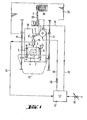
- the grinding tool comprising the grinding motor 1 and the grinding wheel 2 mounted on the motor shaft, is carried by a tool holder 4 movable on rails 5 or on an equivalent system allowing a linear displacement.
- the tool holder 4 is connected via connecting rods 6, 6 ′ to a crank arm 7 which is fixed to the shaft of a constant torque motor 8.
- This constant torque motor 8 is mounted on a carriage 10 on which the rails 5 are fixed.
- the constant torque motor 8 presses the grinding wheel 2 with a predetermined force against the edge of a glass sheet 12.
- the carriage 10 is for its part movable on rails or sliding bars 14, thanks to a motor 38 fixed on a frame 36 and transmitting its movement by means of a toothed belt 39.
- the grinding tool is positioned using the carriage 10, that is to say it is brought into the desired position, while the tool holder 4 movable on the rails 5 is used to exert pressure desired with the grinding tool on the edge of the glass sheet 12.
- a pressure capsule 15 which provides an electrical signal corresponding to the effective grinding pressure.
- This signal also called actual voltage, is brought to a regulating amplifier 17 by line 16, while the set voltage corresponding to the set point of the grinding pressure is brought to the regulating amplifier 17 by the via potentiometer 18.
- the constant torque motor 8 is activated via line 19 by the regulation amplifier 17 which compares the setpoint voltage and the actual voltage. Since no electromotive force appears on the constant torque motor 8, an equivalent resistance 20 is inserted between the regulation amplifier 17 and the constant torque motor 8.
- Figure 1 are only shown rails 14 arranged in a single direction of movement. This system can be used as is in the case where the glass sheet is rotated and the carriage 10 carrying the grinding tool moves in one direction to remain in contact with the edge of the glass sheet.
- FIG. 1 represents only one only direction defined by the rails 14, but the addition of an additional displacement system in a direction perpendicular to the first does not modify the invention. Provision is also made for mounting the assembly ensuring the regulation of the grinding pressure, namely the grinding wheel 2 and its motor 1, the rails 5, the tool holder 4, the motor 8, the connecting rods 6 and 6 ′, the arm crank 7 and the pressure capsule on a rotating disc not shown and adapted to be oriented so as to maintain the rails 5 in a direction perpendicular to the edge of the glass sheet.
- the grinding head can rotate 360 °.
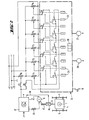
- FIG. 2 illustrates a system for regulating the grinding pressure controlled by a program, this system fitted to a grinding machine having a movement carriage composed in two orthogonal directions X and Y, which carries the grinding tool and which is guided all around the glass sheet, that is to say on the 360 ° of the periphery of the glass sheet, by a guide program.
- the cir baking grinding pressure regulation the grinding pressure of the tool is changed during its path along the edge of the glass sheet, in the sense that it is, for example reduced, when the tool bypasses the portions of glass sheets having angles.
- different reference voltages are used which vary according to the position of the grinding tool.
- the grinding motor 1 is, as described above, mounted on the tool holder 4 which is pressed, by means of the connecting rod 6, the pressure capsule 15 and the connecting rod 6 ', thanks to the constant torque motor 8 , against the edge of the glass sheet.
- the constant torque motor 8 is activated by the regulating amplifier 17 and between this amplifier and the motor 8 is interposed the resistor 20.
- the most important component of the device for "all-round trip programming" is a digital reverse run cam 24.
- This digital counter 24 has ten preset switches 25.
- a relay is associated with each travel cam. preselection 25.
- the relays are designated by Z 1 to Z 10 .
- the preselection switches 25 of the digital counter 24 make it possible to modify, increase or decrease the grinding pressure at particular points in the path of the grinding tool. These points are advantageously determined empirically.
- the advance of the counter 24 is effected by means of the two pulse generators 26 and 27, the generator 26 being coupled to the drive mechanism of the carriage in a direction for example the axis X and the generator 27 being coupled to the drive mechanism in the other direction, for example the Y axis.
- the counter 24 advances by one notch and the number of pulses appears on the table d display 28.
- the associated relay Z 1 to Z 10 trips and closes the corresponding contact thus establishing a circuit passing through one of the potentiometers P l to P 6 .
- the potentiometer P l of the grinding pressure setpoint is associated with the contacts of the relays Z 1 , Z 3 , Z 5 , Z 7 , and Z 9 .
- the potentiometer P 1 determines the basic grinding pressure, which must for example to be exerted on rectilinear portions of the edges.
- Each of the other relays Z 2 , Z 4 , Z 6 , Z 8 and Z 10 is associated with a potentiometer P 2 , P 3 , P 4 , and P 6 corresponding to a different set value.
- the device operates as follows. At the start of the grinding machine, the pulse generators 26, 27 are rotated and clock the advancement of the digital counter 24.
- the preset switches 25 allow the relays Z 1 to Z 10 to operate at determined points of the path. Before the first relay Z 1 is actuated, a basic grinding pressure determined by the potentiometer P 1 is exerted. If, at a chosen point in the route, the relay Z 1 switches, a switchover to the circuit containing the potentiometer P 2 occurs. As soon as another point in the path of the grinding tool set on the next preselection switch is reached, the relay Z 2 is actuated in turn, which has the effect of switching off the potentiometer P 2 and by switching back to potentiometer P 1 .
- the contact d 2 is naturally closed when the machine starts and it remains closed until the entire periphery to be ground has been traversed.
- the contact d 2 is open and the contact d 3 is closed. Closing the contact d 3 has the effect of activating the servo-amplifier 17 by the set value set by the potentiometer P 0 , with the consequence that the carriage 10 (FIG. 1) carrying the tool holder 4 is brought back in its starting position.
- the contact d 1 which erases the digital counter 24, is closed in turn.
- All the data necessary for the grinding of a given glass sheet model can in this way be stored on the same information medium, for example a magnetic strip.
- FIG. 3 A first embodiment allowing the tool holder 4 to rotate with little friction is illustrated in FIG. 3.
- the tool holder 4 has the form of a plate with polished surfaces, on which is fixed a bearing 30 which carries the grinding unit formed by the motor 1 and the grinding wheel 2.
- the constant torque motor 8 acts on the plate 4 by means of the pressure capsule 15 and the crank arm 7.
- the plate 4 is guided between a plate lower support 31 and an upper support plate 32 which for their part are held on their two sides by closure plates 33.
- the set of plates 31, 32, 33 constitutes the carriage 10 which can be moved the along the bars 14 by means of lateral ball bearing bushings 34.
- the bars 14 are mounted using the yokes 35 on the frame 36 of the machine.
- This frame 36 also carries the positioning motor 38 which, by means of the toothed belt 39, moves the carriage 10 according to a program recorded in the direction of the arrow double F, so that the grinding wheel 2 is always guided in the position which, during the rotation of the glass sheet 12, is pre-established and determined by the shape of this sheet of glass glass.
- the constant torque motor 8 which acts via the crank arm 7 on the plate 4 and which determines the pressure force with which the grinding wheel is pressed against the edge of the glass sheet.
- the air cushion between the plate 4 and the upper plate 32 is necessary to compensate for the forces which result from the pressure exerted by the grinding wheel placed below the plate 4 on the edge of the glass sheet.
- the plate 4 is mounted so as to also have little friction on its sides and on its ends.
- Rolling balls 45 mounted additionally in the plates 31, 32 are arranged opposite each face of the plate 4 at a height such that the plate 4 does not come into contact with them when the air cushions are present.
- the rolling balls 45 therefore only fulfill an emergency function and in all cases avoid the friction of the plate 4 against the plates 31 and 32.
- FIG. 4 illustrates another embodiment making it possible to obtain low friction of the tool holder.
- the tool holder comprises a plate 54 mounted oscillating on two pivoting arms 55.
- the pivoting arms 55 are articulated at one end on pivoting yokes 56 provided on a console 57.
- the console 57 is for its part fixed to the carriage , here referenced 58, which can be moved by sliding on the sliding bars 14 already present in the previous embodiment.
- the constant torque motor 8, fixed on a support 60 appears holding on to the carriage 58 acts on the carriage 54 via the crank arm 7 and the manonetric capsule 15.
- the pivoting arms 55 are articulated on the plate 54 by means of pivoting yokes 62.
- the pivoting yokes 56 and 62 include low friction ball bearings. This oscillating arrangement certainly does not allow a strictly linear movement of the plate 54, but this is of no importance for the present case in which there is simply a regulation of the grinding pressure during which the distances traveled are very small.
- the motor 38, the frame element 36 and the toothed belt 39, are those already described in FIG. 1.
Landscapes
- Engineering & Computer Science (AREA)
- Chemical & Material Sciences (AREA)
- Ceramic Engineering (AREA)
- Inorganic Chemistry (AREA)
- Mechanical Engineering (AREA)
- Grinding And Polishing Of Tertiary Curved Surfaces And Surfaces With Complex Shapes (AREA)
Applications Claiming Priority (4)
| Application Number | Priority Date | Filing Date | Title |
|---|---|---|---|
| DE3201495 | 1982-01-20 | ||
| DE3201494 | 1982-01-20 | ||
| DE3201494 | 1982-01-20 | ||
| DE3201495 | 1982-01-20 |
Publications (3)
| Publication Number | Publication Date |
|---|---|
| EP0084504A2 true EP0084504A2 (de) | 1983-07-27 |
| EP0084504A3 EP0084504A3 (en) | 1984-12-27 |
| EP0084504B1 EP0084504B1 (de) | 1988-05-18 |
Family
ID=25798955
Family Applications (1)
| Application Number | Title | Priority Date | Filing Date |
|---|---|---|---|
| EP83400129A Expired EP0084504B1 (de) | 1982-01-20 | 1983-01-19 | Apparat zum Schleifen von Glaskanten |
Country Status (4)
| Country | Link |
|---|---|
| EP (1) | EP0084504B1 (de) |
| DE (1) | DE3376631D1 (de) |
| ES (1) | ES519114A0 (de) |
| PT (1) | PT76124A (de) |
Cited By (4)
| Publication number | Priority date | Publication date | Assignee | Title |
|---|---|---|---|---|
| FR2554375A1 (fr) * | 1983-11-09 | 1985-05-10 | Saint Gobain Vitrage | Maintien de feuilles de verre par electro-aimant |
| EP0168311A3 (en) * | 1984-06-30 | 1987-12-09 | Saint-Gobain Vitrage | Grinding machine with control circuit for positioning the tool carriage |
| EP0233159A3 (en) * | 1986-02-04 | 1989-10-11 | Societa' Italiana Vetro - Siv - S.P.A. | An improved machine for grinding the edges of a sheet of glass, particularly for automobile windows |
| EP0457364A3 (en) * | 1985-11-04 | 1992-05-13 | Silicon Technology Corporation | Automatic edge grinder |
Family Cites Families (4)
| Publication number | Priority date | Publication date | Assignee | Title |
|---|---|---|---|---|
| FR1588348A (de) * | 1968-10-14 | 1970-04-10 | ||
| US3803772A (en) * | 1970-08-14 | 1974-04-16 | Cincinnati Milacron Heald | Grinding machine |
| JPS5089777A (de) * | 1973-12-18 | 1975-07-18 | ||
| BE837728A (fr) * | 1976-01-20 | 1976-05-14 | Machine a faconner les bords de feuilles planes |
-
1983
- 1983-01-19 ES ES519114A patent/ES519114A0/es active Granted
- 1983-01-19 EP EP83400129A patent/EP0084504B1/de not_active Expired
- 1983-01-19 DE DE8383400129T patent/DE3376631D1/de not_active Expired
- 1983-01-20 PT PT76124A patent/PT76124A/pt unknown
Cited By (4)
| Publication number | Priority date | Publication date | Assignee | Title |
|---|---|---|---|---|
| FR2554375A1 (fr) * | 1983-11-09 | 1985-05-10 | Saint Gobain Vitrage | Maintien de feuilles de verre par electro-aimant |
| EP0168311A3 (en) * | 1984-06-30 | 1987-12-09 | Saint-Gobain Vitrage | Grinding machine with control circuit for positioning the tool carriage |
| EP0457364A3 (en) * | 1985-11-04 | 1992-05-13 | Silicon Technology Corporation | Automatic edge grinder |
| EP0233159A3 (en) * | 1986-02-04 | 1989-10-11 | Societa' Italiana Vetro - Siv - S.P.A. | An improved machine for grinding the edges of a sheet of glass, particularly for automobile windows |
Also Published As
| Publication number | Publication date |
|---|---|
| ES8400043A1 (es) | 1983-11-01 |
| EP0084504A3 (en) | 1984-12-27 |
| DE3376631D1 (en) | 1988-06-23 |
| EP0084504B1 (de) | 1988-05-18 |
| ES519114A0 (es) | 1983-11-01 |
| PT76124A (fr) | 1983-02-01 |
Similar Documents
| Publication | Publication Date | Title |
|---|---|---|
| EP0084505A2 (de) | Steuerungsverfahren für eine Maschine zum Schleifen der Kanten von Glasplatten und Vorrichtungen zum Ausführen dieses Verfahrens | |
| EP0084506A2 (de) | Verfahren und Vorrichtung zur Positionierung einer Maschine zur Bearbeitung der Kanten von Glasplatten | |
| FR2516746A1 (fr) | Dispositif d'affutage des couteaux hacheurs de machines de hachage a tambour | |
| FR2475430A1 (fr) | Appareil pour ebouter ou pour couper des bouts a essayer d'extremites de feuillard enroule en bobines | |
| EP0084504B1 (de) | Apparat zum Schleifen von Glaskanten | |
| FR2656666A1 (fr) | Dispositif de transfert a va-et-vient. | |
| EP0298056B1 (de) | Biegepresse für Bleche | |
| EP0168311B1 (de) | Schleifmaschine mit einem Regelkreis zum Positionieren des Werkzeugschlittens | |
| FR2647386A1 (fr) | Dispositif de tracage et de coupe partielle en epaisseur d'un complexe multicouche adhesif protege et machine en faisant application | |
| EP2247404B1 (de) | Markierungsmaschine | |
| FR2501098A1 (fr) | Machine pour le decoupage de rouleaux de tissu | |
| FR2522296A1 (fr) | Appareil pour la decoupe de blocs de mousse | |
| EP0323364A1 (de) | Bearbeitungskopf für eine Maschine zur Bearbeitung von Bäumen | |
| FR2479736A1 (fr) | Machine a travailler la pierre a commande par gabarit | |
| FR2825652A1 (fr) | Machine d'usinage par abrasif de portees d'une piece, notamment de superfinition de manetons de vilebrequins | |
| FR2612827A1 (fr) | Machine de deroulage de bille de bois pourvue de rouleaux de support rotatifs et mobiles | |
| FR2490532A1 (fr) | Dispositif destine a arrondir les coins de plaques de verre | |
| EP0266290A1 (de) | Verfahren und Vorrichtung zum Zuführen an einer Schneidvorrichtung | |
| FR2673925A1 (fr) | Empileur de sortie dans des machines d'impression. | |
| EP0291383B1 (de) | Verfahren und Vorrichtung zur Wärmebehandlung von Nockenwellen | |
| FR2614834A1 (fr) | Procede et dispositif pour le calandrage des vitrages feuilletes | |
| FR2587724A1 (fr) | Machine pour le travail mecanique en continu des peaux en megisserie et en tannerie | |
| FR2560538A1 (fr) | Affuteuse pour chaines a gouges a dispositif de detection, d'avance et de blocage de la chaine | |
| FR2586707A1 (fr) | Dispositif d'entrainement d'une peau, adaptable sur une machine de tannerie | |
| FR2774011A1 (fr) | Dispositif de presertissage et/ou de sertissage |
Legal Events
| Date | Code | Title | Description |
|---|---|---|---|
| PUAI | Public reference made under article 153(3) epc to a published international application that has entered the european phase |
Free format text: ORIGINAL CODE: 0009012 |
|
| AK | Designated contracting states |
Designated state(s): BE CH DE FR GB IT LI LU NL SE |
|
| RAP1 | Party data changed (applicant data changed or rights of an application transferred) |
Owner name: SAINT-GOBAIN VITRAGE Owner name: VEGLA VEREINIGTE GLASWERKE GMBH |
|
| PUAL | Search report despatched |
Free format text: ORIGINAL CODE: 0009013 |
|
| AK | Designated contracting states |
Designated state(s): BE CH DE FR GB IT LI LU NL SE |
|
| 17P | Request for examination filed |
Effective date: 19850607 |
|
| 17Q | First examination report despatched |
Effective date: 19860415 |
|
| GRAA | (expected) grant |
Free format text: ORIGINAL CODE: 0009210 |
|
| AK | Designated contracting states |
Kind code of ref document: B1 Designated state(s): BE CH DE FR GB IT LI LU NL SE |
|
| PG25 | Lapsed in a contracting state [announced via postgrant information from national office to epo] |
Ref country code: NL Effective date: 19880518 |
|
| PG25 | Lapsed in a contracting state [announced via postgrant information from national office to epo] |
Ref country code: SE Effective date: 19880531 |
|
| REF | Corresponds to: |
Ref document number: 3376631 Country of ref document: DE Date of ref document: 19880623 |
|
| ITF | It: translation for a ep patent filed | ||
| GBT | Gb: translation of ep patent filed (gb section 77(6)(a)/1977) | ||
| NLV1 | Nl: lapsed or annulled due to failure to fulfill the requirements of art. 29p and 29m of the patents act | ||
| PG25 | Lapsed in a contracting state [announced via postgrant information from national office to epo] |
Ref country code: LU Free format text: LAPSE BECAUSE OF NON-PAYMENT OF DUE FEES Effective date: 19890131 |
|
| PLBE | No opposition filed within time limit |
Free format text: ORIGINAL CODE: 0009261 |
|
| STAA | Information on the status of an ep patent application or granted ep patent |
Free format text: STATUS: NO OPPOSITION FILED WITHIN TIME LIMIT |
|
| 26N | No opposition filed | ||
| ITTA | It: last paid annual fee | ||
| PGFP | Annual fee paid to national office [announced via postgrant information from national office to epo] |
Ref country code: DE Payment date: 19920320 Year of fee payment: 10 |
|
| PG25 | Lapsed in a contracting state [announced via postgrant information from national office to epo] |
Ref country code: DE Effective date: 19931001 |
|
| PGFP | Annual fee paid to national office [announced via postgrant information from national office to epo] |
Ref country code: GB Payment date: 19981221 Year of fee payment: 17 |
|
| PGFP | Annual fee paid to national office [announced via postgrant information from national office to epo] |
Ref country code: BE Payment date: 19990128 Year of fee payment: 17 |
|
| PGFP | Annual fee paid to national office [announced via postgrant information from national office to epo] |
Ref country code: CH Payment date: 19990422 Year of fee payment: 17 |
|
| PG25 | Lapsed in a contracting state [announced via postgrant information from national office to epo] |
Ref country code: GB Free format text: LAPSE BECAUSE OF NON-PAYMENT OF DUE FEES Effective date: 20000119 |
|
| PGFP | Annual fee paid to national office [announced via postgrant information from national office to epo] |
Ref country code: FR Payment date: 20000126 Year of fee payment: 18 |
|
| PG25 | Lapsed in a contracting state [announced via postgrant information from national office to epo] |
Ref country code: BE Free format text: LAPSE BECAUSE OF NON-PAYMENT OF DUE FEES Effective date: 20000131 Ref country code: LI Free format text: LAPSE BECAUSE OF NON-PAYMENT OF DUE FEES Effective date: 20000131 Ref country code: CH Free format text: LAPSE BECAUSE OF NON-PAYMENT OF DUE FEES Effective date: 20000131 |
|
| BERE | Be: lapsed |
Owner name: VEGLA VEREINIGTE GLASWERKE G.M.B.H. Effective date: 20000131 Owner name: SAINT-GOBAIN VITRAGE Effective date: 20000131 |
|
| GBPC | Gb: european patent ceased through non-payment of renewal fee |
Effective date: 20000119 |
|
| REG | Reference to a national code |
Ref country code: CH Ref legal event code: PL |
|
| PG25 | Lapsed in a contracting state [announced via postgrant information from national office to epo] |
Ref country code: FR Free format text: LAPSE BECAUSE OF NON-PAYMENT OF DUE FEES Effective date: 20000929 |
|
| REG | Reference to a national code |
Ref country code: FR Ref legal event code: ST |