EP0085582A1 - Protection cathodique utilisant un béton polymère conducteur - Google Patents
Protection cathodique utilisant un béton polymère conducteur Download PDFInfo
- Publication number
- EP0085582A1 EP0085582A1 EP83300579A EP83300579A EP0085582A1 EP 0085582 A1 EP0085582 A1 EP 0085582A1 EP 83300579 A EP83300579 A EP 83300579A EP 83300579 A EP83300579 A EP 83300579A EP 0085582 A1 EP0085582 A1 EP 0085582A1
- Authority
- EP
- European Patent Office
- Prior art keywords
- anode
- set forth
- concrete
- conductive
- polymer
- Prior art date
- Legal status (The legal status is an assumption and is not a legal conclusion. Google has not performed a legal analysis and makes no representation as to the accuracy of the status listed.)
- Withdrawn
Links
- 238000004210 cathodic protection Methods 0.000 title claims abstract description 50
- 229920001940 conductive polymer Polymers 0.000 title claims description 23
- 239000002986 polymer concrete Substances 0.000 title abstract description 37
- 239000004567 concrete Substances 0.000 claims abstract description 50
- 229910001294 Reinforcing steel Inorganic materials 0.000 claims abstract description 23
- 239000012530 fluid Substances 0.000 claims abstract description 13
- 239000002006 petroleum coke Substances 0.000 claims abstract description 13
- 229920005989 resin Polymers 0.000 claims description 38
- 239000011347 resin Substances 0.000 claims description 38
- 239000000203 mixture Substances 0.000 claims description 29
- 229920000642 polymer Polymers 0.000 claims description 22
- 238000000034 method Methods 0.000 claims description 14
- 229920000647 polyepoxide Polymers 0.000 claims description 12
- 229920001225 polyester resin Polymers 0.000 claims description 12
- 239000004645 polyester resin Substances 0.000 claims description 12
- 229920001567 vinyl ester resin Polymers 0.000 claims description 12
- 239000003822 epoxy resin Substances 0.000 claims description 11
- 239000011236 particulate material Substances 0.000 claims description 10
- 239000004593 Epoxy Substances 0.000 claims description 9
- 239000002952 polymeric resin Substances 0.000 claims description 9
- 229920003002 synthetic resin Polymers 0.000 claims description 9
- LNEPOXFFQSENCJ-UHFFFAOYSA-N haloperidol Chemical compound C1CC(O)(C=2C=CC(Cl)=CC=2)CCN1CCCC(=O)C1=CC=C(F)C=C1 LNEPOXFFQSENCJ-UHFFFAOYSA-N 0.000 claims description 6
- 238000009877 rendering Methods 0.000 claims description 2
- 239000000835 fiber Substances 0.000 claims 2
- 238000011065 in-situ storage Methods 0.000 claims 2
- 230000001681 protective effect Effects 0.000 claims 1
- 239000002344 surface layer Substances 0.000 claims 1
- 239000002245 particle Substances 0.000 abstract description 13
- 239000000463 material Substances 0.000 abstract description 11
- 239000000571 coke Substances 0.000 description 27
- VYPSYNLAJGMNEJ-UHFFFAOYSA-N Silicium dioxide Chemical compound O=[Si]=O VYPSYNLAJGMNEJ-UHFFFAOYSA-N 0.000 description 15
- 239000011398 Portland cement Substances 0.000 description 14
- 238000012360 testing method Methods 0.000 description 14
- 239000004576 sand Substances 0.000 description 11
- OKTJSMMVPCPJKN-UHFFFAOYSA-N Carbon Chemical compound [C] OKTJSMMVPCPJKN-UHFFFAOYSA-N 0.000 description 7
- 229910052799 carbon Inorganic materials 0.000 description 7
- 230000007797 corrosion Effects 0.000 description 7
- 238000005260 corrosion Methods 0.000 description 7
- 230000006866 deterioration Effects 0.000 description 7
- 150000003839 salts Chemical class 0.000 description 7
- GWEVSGVZZGPLCZ-UHFFFAOYSA-N Titan oxide Chemical compound O=[Ti]=O GWEVSGVZZGPLCZ-UHFFFAOYSA-N 0.000 description 6
- YXFVVABEGXRONW-UHFFFAOYSA-N Toluene Chemical compound CC1=CC=CC=C1 YXFVVABEGXRONW-UHFFFAOYSA-N 0.000 description 6
- 239000003973 paint Substances 0.000 description 6
- 239000000523 sample Substances 0.000 description 6
- RYGMFSIKBFXOCR-UHFFFAOYSA-N Copper Chemical compound [Cu] RYGMFSIKBFXOCR-UHFFFAOYSA-N 0.000 description 5
- 229920000728 polyester Polymers 0.000 description 5
- ZAMOUSCENKQFHK-UHFFFAOYSA-N Chlorine atom Chemical compound [Cl] ZAMOUSCENKQFHK-UHFFFAOYSA-N 0.000 description 4
- 239000002253 acid Substances 0.000 description 4
- 239000000654 additive Substances 0.000 description 4
- 239000000460 chlorine Substances 0.000 description 4
- 229910052801 chlorine Inorganic materials 0.000 description 4
- 229910052802 copper Inorganic materials 0.000 description 4
- 239000010949 copper Substances 0.000 description 4
- 230000006378 damage Effects 0.000 description 4
- BASFCYQUMIYNBI-UHFFFAOYSA-N platinum Chemical compound [Pt] BASFCYQUMIYNBI-UHFFFAOYSA-N 0.000 description 4
- 230000010287 polarization Effects 0.000 description 4
- 229910052709 silver Inorganic materials 0.000 description 4
- 239000004332 silver Substances 0.000 description 4
- 230000003068 static effect Effects 0.000 description 4
- XLYOFNOQVPJJNP-UHFFFAOYSA-N water Substances O XLYOFNOQVPJJNP-UHFFFAOYSA-N 0.000 description 4
- VEXZGXHMUGYJMC-UHFFFAOYSA-M Chloride anion Chemical compound [Cl-] VEXZGXHMUGYJMC-UHFFFAOYSA-M 0.000 description 3
- 230000009102 absorption Effects 0.000 description 3
- 238000010521 absorption reaction Methods 0.000 description 3
- 238000010276 construction Methods 0.000 description 3
- 238000005259 measurement Methods 0.000 description 3
- 230000028161 membrane depolarization Effects 0.000 description 3
- 239000011150 reinforced concrete Substances 0.000 description 3
- 239000000126 substance Substances 0.000 description 3
- 239000004408 titanium dioxide Substances 0.000 description 3
- LCFVJGUPQDGYKZ-UHFFFAOYSA-N Bisphenol A diglycidyl ether Chemical compound C=1C=C(OCC2OC2)C=CC=1C(C)(C)C(C=C1)=CC=C1OCC1CO1 LCFVJGUPQDGYKZ-UHFFFAOYSA-N 0.000 description 2
- KZBUYRJDOAKODT-UHFFFAOYSA-N Chlorine Chemical compound ClCl KZBUYRJDOAKODT-UHFFFAOYSA-N 0.000 description 2
- FAPWRFPIFSIZLT-UHFFFAOYSA-M Sodium chloride Chemical compound [Na+].[Cl-] FAPWRFPIFSIZLT-UHFFFAOYSA-M 0.000 description 2
- 229910000831 Steel Inorganic materials 0.000 description 2
- 230000004913 activation Effects 0.000 description 2
- 230000015556 catabolic process Effects 0.000 description 2
- 150000003841 chloride salts Chemical class 0.000 description 2
- 229910000365 copper sulfate Inorganic materials 0.000 description 2
- 238000006731 degradation reaction Methods 0.000 description 2
- 230000005611 electricity Effects 0.000 description 2
- 230000009969 flowable effect Effects 0.000 description 2
- 238000009434 installation Methods 0.000 description 2
- 239000004816 latex Substances 0.000 description 2
- 229920000126 latex Polymers 0.000 description 2
- 229910052751 metal Inorganic materials 0.000 description 2
- 239000002184 metal Substances 0.000 description 2
- 239000013618 particulate matter Substances 0.000 description 2
- 229910052697 platinum Inorganic materials 0.000 description 2
- 239000010959 steel Substances 0.000 description 2
- 229920013683 Celanese Polymers 0.000 description 1
- 239000006004 Quartz sand Substances 0.000 description 1
- 229910021607 Silver chloride Inorganic materials 0.000 description 1
- 238000005299 abrasion Methods 0.000 description 1
- 230000000996 additive effect Effects 0.000 description 1
- 239000010405 anode material Substances 0.000 description 1
- 230000015572 biosynthetic process Effects 0.000 description 1
- 230000000740 bleeding effect Effects 0.000 description 1
- 239000003054 catalyst Substances 0.000 description 1
- 239000003795 chemical substances by application Substances 0.000 description 1
- GTKRFUAGOKINCA-UHFFFAOYSA-M chlorosilver;silver Chemical compound [Ag].[Ag]Cl GTKRFUAGOKINCA-UHFFFAOYSA-M 0.000 description 1
- 239000011248 coating agent Substances 0.000 description 1
- 238000000576 coating method Methods 0.000 description 1
- 239000000084 colloidal system Substances 0.000 description 1
- 239000007822 coupling agent Substances 0.000 description 1
- 230000032798 delamination Effects 0.000 description 1
- ZOMNIUBKTOKEHS-UHFFFAOYSA-L dimercury dichloride Chemical class Cl[Hg][Hg]Cl ZOMNIUBKTOKEHS-UHFFFAOYSA-L 0.000 description 1
- 230000000694 effects Effects 0.000 description 1
- 125000003700 epoxy group Chemical group 0.000 description 1
- 238000002347 injection Methods 0.000 description 1
- 239000007924 injection Substances 0.000 description 1
- 239000012212 insulator Substances 0.000 description 1
- 230000007774 longterm Effects 0.000 description 1
- 239000003550 marker Substances 0.000 description 1
- 230000003472 neutralizing effect Effects 0.000 description 1
- 229910052758 niobium Inorganic materials 0.000 description 1
- 239000010955 niobium Substances 0.000 description 1
- GUCVJGMIXFAOAE-UHFFFAOYSA-N niobium atom Chemical compound [Nb] GUCVJGMIXFAOAE-UHFFFAOYSA-N 0.000 description 1
- 230000035515 penetration Effects 0.000 description 1
- 230000000704 physical effect Effects 0.000 description 1
- 229920003023 plastic Polymers 0.000 description 1
- 239000004033 plastic Substances 0.000 description 1
- 229920003229 poly(methyl methacrylate) Polymers 0.000 description 1
- 239000010453 quartz Substances 0.000 description 1
- 230000002787 reinforcement Effects 0.000 description 1
- 238000011160 research Methods 0.000 description 1
- 239000012266 salt solution Substances 0.000 description 1
- 238000009938 salting Methods 0.000 description 1
- 239000000377 silicon dioxide Substances 0.000 description 1
- HKZLPVFGJNLROG-UHFFFAOYSA-M silver monochloride Chemical compound [Cl-].[Ag+] HKZLPVFGJNLROG-UHFFFAOYSA-M 0.000 description 1
- 239000011780 sodium chloride Substances 0.000 description 1
- 239000000243 solution Substances 0.000 description 1
- 230000001629 suppression Effects 0.000 description 1
- 230000008646 thermal stress Effects 0.000 description 1
- 230000035899 viability Effects 0.000 description 1
- 238000005303 weighing Methods 0.000 description 1
- 239000000080 wetting agent Substances 0.000 description 1
Images



Classifications
-
- C—CHEMISTRY; METALLURGY
- C23—COATING METALLIC MATERIAL; COATING MATERIAL WITH METALLIC MATERIAL; CHEMICAL SURFACE TREATMENT; DIFFUSION TREATMENT OF METALLIC MATERIAL; COATING BY VACUUM EVAPORATION, BY SPUTTERING, BY ION IMPLANTATION OR BY CHEMICAL VAPOUR DEPOSITION, IN GENERAL; INHIBITING CORROSION OF METALLIC MATERIAL OR INCRUSTATION IN GENERAL
- C23F—NON-MECHANICAL REMOVAL OF METALLIC MATERIAL FROM SURFACE; INHIBITING CORROSION OF METALLIC MATERIAL OR INCRUSTATION IN GENERAL; MULTI-STEP PROCESSES FOR SURFACE TREATMENT OF METALLIC MATERIAL INVOLVING AT LEAST ONE PROCESS PROVIDED FOR IN CLASS C23 AND AT LEAST ONE PROCESS COVERED BY SUBCLASS C21D OR C22F OR CLASS C25
- C23F13/00—Inhibiting corrosion of metals by anodic or cathodic protection
- C23F13/02—Inhibiting corrosion of metals by anodic or cathodic protection cathodic; Selection of conditions, parameters or procedures for cathodic protection, e.g. of electrical conditions
- C23F13/06—Constructional parts, or assemblies of cathodic-protection apparatus
- C23F13/08—Electrodes specially adapted for inhibiting corrosion by cathodic protection; Manufacture thereof; Conducting electric current thereto
- C23F13/16—Electrodes characterised by the combination of the structure and the material
-
- C—CHEMISTRY; METALLURGY
- C23—COATING METALLIC MATERIAL; COATING MATERIAL WITH METALLIC MATERIAL; CHEMICAL SURFACE TREATMENT; DIFFUSION TREATMENT OF METALLIC MATERIAL; COATING BY VACUUM EVAPORATION, BY SPUTTERING, BY ION IMPLANTATION OR BY CHEMICAL VAPOUR DEPOSITION, IN GENERAL; INHIBITING CORROSION OF METALLIC MATERIAL OR INCRUSTATION IN GENERAL
- C23F—NON-MECHANICAL REMOVAL OF METALLIC MATERIAL FROM SURFACE; INHIBITING CORROSION OF METALLIC MATERIAL OR INCRUSTATION IN GENERAL; MULTI-STEP PROCESSES FOR SURFACE TREATMENT OF METALLIC MATERIAL INVOLVING AT LEAST ONE PROCESS PROVIDED FOR IN CLASS C23 AND AT LEAST ONE PROCESS COVERED BY SUBCLASS C21D OR C22F OR CLASS C25
- C23F13/00—Inhibiting corrosion of metals by anodic or cathodic protection
- C23F13/02—Inhibiting corrosion of metals by anodic or cathodic protection cathodic; Selection of conditions, parameters or procedures for cathodic protection, e.g. of electrical conditions
- C23F13/06—Constructional parts, or assemblies of cathodic-protection apparatus
- C23F13/08—Electrodes specially adapted for inhibiting corrosion by cathodic protection; Manufacture thereof; Conducting electric current thereto
-
- C—CHEMISTRY; METALLURGY
- C23—COATING METALLIC MATERIAL; COATING MATERIAL WITH METALLIC MATERIAL; CHEMICAL SURFACE TREATMENT; DIFFUSION TREATMENT OF METALLIC MATERIAL; COATING BY VACUUM EVAPORATION, BY SPUTTERING, BY ION IMPLANTATION OR BY CHEMICAL VAPOUR DEPOSITION, IN GENERAL; INHIBITING CORROSION OF METALLIC MATERIAL OR INCRUSTATION IN GENERAL
- C23F—NON-MECHANICAL REMOVAL OF METALLIC MATERIAL FROM SURFACE; INHIBITING CORROSION OF METALLIC MATERIAL OR INCRUSTATION IN GENERAL; MULTI-STEP PROCESSES FOR SURFACE TREATMENT OF METALLIC MATERIAL INVOLVING AT LEAST ONE PROCESS PROVIDED FOR IN CLASS C23 AND AT LEAST ONE PROCESS COVERED BY SUBCLASS C21D OR C22F OR CLASS C25
- C23F2201/00—Type of materials to be protected by cathodic protection
- C23F2201/02—Concrete, e.g. reinforced
Definitions
- the present invention is a polymer concrete that can be applied to the surface of a bridge deck or other concrete structure and carry an impressed current to protect the reinforcing steel from corrosion.
- a primary area of compatibility is coefficient of thermal expansion; if the coefficient of thermal expansion of the polymer is different from that of concrete, the polymer must be sufficiently flexible to dissipate thermal stresses.
- a certain rigid polymer was used to attach lane markers to a concrete highway. The coefficient of expansion of the polymer was different from that of concrete, and the cured polymer was too hard to stretch or compress to absorb the difference in expansions.
- the cured polymer be able to withstand the rigors of traffic driving over it day after day. This requires that it retain some flexibility when subjected to cold temperatures so that it does not crack when pounded by heavy trucks, but not become too soft in summer.
- the purpose of the polymer is to carry current as part of a cathodic protection system for the reinforcing steel.
- a polymer is more desireable in this application than portland cement concrete, because the polymer is more resistant to acid attack.
- the prior art shows many examples of polymers that have conductive particles in them which are used as floor coverings for static electricity buildup suppression. It has been found that while these polymers may be effective in preventing static electricity buildup, they are sometimes totally unsuitable for use in the environment of the present invention, which is a bridge deck, roadway, or other reinforced concrete member.
- the cured polymer concrete have as low an electrical resistance as possible in order to reduce the voltage that has to be applied to it and/or the thickness of nabit. material.which must be used.
- the conductivity is primarily a function of the particles added to the polymer, although as will be shown applicants have found that the properties of the polymer itself play a significant role in this.
- the prior art shows many different types of particles that can be added to polyester and epoxy resins to get low resistance, but no examples were found of a cured polymer that was used to carry currents of the order of 1 amp or more and which had the extremely low resistance of the polymer of the present invention.
- a method of cathodically protecting reinforcing steel in concrete which includes impressing an electrical current from at least one anode to the reinforcing steel, characterized in that the anode is formed at least in part by mixing thoroughly a conductive particulate material and an uncured polymer resin selected from a group of polymer resins which compact the particulate material upon curing thus rendering the anode significantly more conductive, curing such polymer resin to form a cured polymer, and then impressing such current between the anode and reinforcing steel.
- polyester or vinyl ester resin having carbon particles distributed within it which is used to carry electric current; the resin is applied to a bridge deck or other reinforced concrete structure and is used in an impressed current cathodic protection circuit as one of the current-carrying members.
- the resins have the proper physical properties which allow them to be used on portland cement concrete, and are very resistant to destruction by the acid and the chlorine gas formed when used in the presence of chloride-containing salts.
- Figure la shows a cross section of a bridge deck or roadway that has the present invention applied to it.
- the portland cement concrete portion 10 is of conventional construction, comprising portland cement concrete 12 with reinforcing steel members 14 within it.
- a relatively thin (of the order 0.1 inch) layer of the polymer concrete 16 of the present invention having primary anodes 18 within it.
- Polymer concrete layer 16 is part of an impressed current cathodic protection system (not shown) which is designed to prevent the deterioration of the reinforcing steel members 14 within the portland cement concrete.
- Figure lb shows an alternative method of placing anodes 18.
- slots 19 are cut in the existing surface and anodes 18 are placed in the slots.
- the slots are then filled with conductive polymer, and the surface is covered with a thin layer of conductive polymer as in Figure la or a coat of conductive paint may be applied as in the example of Figures 3 and 4.
- Conductive paint can be used where the surface is not subjected to abrasion from foot or vehicle traffic (the side of a retaining wall, for example).
- Figure lc shows another alternative, the close spacing of anodes (primary anode (metal or carbon strand) and conductive polymer concrete) to eliminate the need for a continuous conductive layer on the surface.
- anodes primary anode (metal or carbon strand) and conductive polymer concrete
- the deterioration of the members 14 is due to the formation of natural electric currents which result from the penetration of chloride salts and the different electrical potentials along the members 14 within the portland cement concrete 12. Stopping of the deterioration can be achieved by impressing a current on the reinforcing steel and making all the steel in the concrete cathodic, thus neutralizing the naturally occurring electric currents.
- Primary anodes 18 carry the impressed current, and polymer concrete 16 distributes this current evenly to the reinforcing steel of the bridge deck or roadway thus providing the "couple" between the existing concrete and the primary anode. It is obvious that primary anodes 18 could be incorporated within the body of portland cememt concrete 12 in new construction. Applicants' invention, however, is intended for use on existing structures; in these applications it is difficult or impossible to reconstruct the bridge or road, hence the impressed current carrying part of the circuit must be an overlay on the existing surface or in slots placed in the existing surface. Further, acid is formed near the primary anode 18. This will destroy the portland cement concrete, whereas the polymer concrete is immune to such destruction. Such acid attack of a portland cement based anode backfill material resulted in deterioration of the backfill and exposure of the anode wire in tests on large slabs and on bridge decks after only several months of use.
- the deterioration of the epoxy resin has been determined to be a result of attack by the nascent chlorine formed by the passage of current through the resin, the chlorine coming from the deicing salt in the water. Since existing bridge decks contain the chloride salt in the concrete already and will receive more salt to eliminate icing conditions in winter, a resin overlay or primary anode encapsulent will also be subject to this condition and clearly the epoxy resins are not suitable for use.
- Polyester resins show little deterioration after 16 days under the same conditions of current and salt solution. Since this current level is much higher than would be used in practice, it is felt that the test shows that polyester resins are suitable for long-term use. Further, vinyl ester resins have been found to be even more resistant to degradation and thus can be used in high current density applications.
- calcined fluid petroleum coke is the preferred particulate material for imparting electrical conductivity.
- this material does not produce the desired results when used with all resins.
- the resulting conductivities were unacceptably high (from 30.7 to 5.5 million ohm-cm when mixed with calcined fluid petroleum coke).
- the resin did not set (harden).
- sand or other fine aggregate was added along with the coke, the material became an insulator (it had a resistance in excess of 64 million ohm-cm).
- epoxy resin which gave marginally acceptable resistivity, Epi Rez 510 (made by Celanese Plastics and Specialty Co., 1065 West Hill Street, P.O. Box 8248, Louisville, KY 40208), which when mixed with toluene and a curing agent and coke gave a resistivity of 3-4 ohm-cm.
- Epi Rez 510 made by Celanese Plastics and Specialty Co., 1065 West Hill Street, P.O. Box 8248, Louisville, KY 40208
- epoxy resins do not withstand the attack by chlorine gas which results from the passage of current in the presence of deicing chemicals.
- item no. 3 is an example of the invention and the other items are for comparison to demonstrate the point mentioned above.
- conductive concretes with electrical resistivities varying from 0.8 to 3.4 ohm-cm can be made using:
- Consistency of the mixture can be varied from stiff but trowelable to easily pourable.
- the material may be colored gray with only a modest increase in resistivity.
- Trowelable mix, 52 percent sand and 48 percent coke 0.07 percent absorption.
- the conductive polymer concrete was utilized to embed platinum and niobium clad, copper core primary anode lines in slots placed in an existing 4 feet x 5 feet x 8.5 inch reinforced concrete slab.
- the top mat reinforcing steel in the slab was corroding due to the intrusion of chloride into the concrete during 7 years of daily salting.
- the polyester resin trowelable mix with all coke aggregate (Mix 1 in Table A) was utilized as the slot-fill material (slot size approximately 0.5 inch x 0.5 inch) and after set, a layer of conductive paint (Acheson Colloids Electrodag 188) was applied to the surface. The paint was omitted on small areas of the slab to facilitate potential measurements.
- Figures 3 and 4 provide a plan view of the surface of the slab showing top reinforcing steel locations, the rate of corrosion probe location, anode locations, and the locations of the unpainted spots used for potential measurements.
- the potentials were measured using portable copper/copper sulfate cells placed on the unpainted concrete.
- the cathodic protection (CP) system was activated using anode 1 only and a constant current of 35 mA (1.75 mA/ft 2 of concrete surface; 9.9 mA/ft 2 of top mat rebar; and 3.5 mA/ft 2 of total rebar).
- System voltage was 2.0 volts and the concrete temperature averaged 18.3 0 C.
- Table C shows the electrical potentials of the top mat reinforcing steel before CP activation, the instant off potentials 30 minutes after activation, and the differences in potential due to CP. These data show conclusively that the steel can be polarized using this cathodic protection system.
- "Throwing power" of a single slot anode is at least 3 feet (the maximum length tested).
- the cathodic protection system on this slab was operated at various currents and voltages for five months. A total of about 75 ampere- hours of current was passed without degradation of the conductive polymer concrete. Bond of the conductive polymer concrete to the portland cement concrete is excellent. Additionally, no large driving voltage increases have occurred during constant current tests, thus indicating that primary anode gas blockage is not a problem, even during a 2-day high current test when 300 mA was applied, and all top mat reinforcing steel was polarized to instant off potential more negative than -1.01 volts saturated Calomel Standard Electrode (CSE). The rate of corrosion probe in the slab has indicated a zero corrosion rate.
- CSE Calomel Standard Electrode
- Cathodic protection was applied to another 20 ft 2 slab using the conductive polymer concrete. Slab construction, reinforcement, slot size, primary anode material and locations, and previous exposure history were the same for this slab as for that described previously.
- the slab surface was sandblasted and a 4 layer built-up polymer concrete overlay was placed.
- a layer of resin with additives is spread on the surface, aggregate is broadcast onto the resin and then the material is rolled. After this material has cured, the excess aggregate is removed and a second layer is applied in an identical manner.
- the first two layers of this overlay were made conductive through the use of Loresco DW2 coke as the sole aggregate.
- An angular quartz aggregate was used for the final two nonconductive layers.
- the overlay was indeed conductive.
- the 1000-cycle AC resistance between the two metal anode wires was 2380 ohms when the slots were simply filled with dry DW2 coke. After filling the slots with conductive polymer concrete and placing the built-up overlay, the anode to anode resistance was 10.2 ohms.
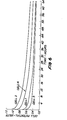
- the CP system was activated using anode 2 only and currents varying from 17 to 25mA. Two days later the current was increased to 30mA and the CP rectifier was set to constant current for 25 days. At that time, control at a constant voltage of 3.0 volts was initiated. Current output typically varied between 30 and 40mA depending primarily upon concrete temperature. Testing has repeatedly indicated that this CP system is functioning quite well. For example, the following data were obtained during depolarization tests (system current prior to shutdown was 38mA (1.9 mA/ft 2 of concrete surface; 10.7 mA/ft of top mat rebar; and 3.8mA/ft 2 of total rebar)):
- the conductive polymer concrete cathodic protection system was installed on a ll3 ft 2 section of bridge deck which had been extracted from a 22-year old bridge deck that was being removed because of corrosion induced concrete damage.
- the slab was transported to Fairbank Highway Research Station and placed on 3-foot high posts. All exposed rebars on the slab edges were wired together to insure continuity and the edges were coated with 2 layers of epoxy paint.
- Cathodic protection instrumentation reference cells, rate of corrosion probes and thermocouples
- the reference cells for this slab were silver/silver chloride rather than the copper/copper sulfate cells used previously.
- FIG. 5 is a plan view of the slab with the position of all top mat reinforcing steel, anode lines and CP instrumentation shown. Installation procedures were identical to those used on the previous slab with the single exception that the original deck surface was scarified and sandblasted prior to overlay placement.
- Table D summarizes the electrical resistance data taken before, during and after system installation. Obviously, a very conductive slot fill and overlay resulted. For example, the 1000 cyele-AC resistance between anode 1 and anode 3 (15 feet apart) prior to overlay placement was 822 ohms, whereas this resistance the day after placement was 7.07 ohms.
- the cathodic protection system was activated the following day. Static (before CP) electrical potentials indicated by the 4 silver-silver chloride reference cells are given below:
- the system rectifier was TASC V automatic instant OFF potential controlled SCR rectifier. Only anode line 1 (on one edge of the slab) was activated and system control was obtained by presetting the desired reference cell 4 set potential at -0.78V (equivalent to -0.85V CSE). Cell 4 we E used because it is the embedded cell positioned the greatest distance from anode 1 (12 feet). The system was then activated and within 3 minutes the desired set point was achieved. With the system operation at 4.0 volts and 0.35 amps the following instant OFF reference cell potential were recorded: "TASC" is a trade name of Harco Corporation.
- the large scale bridge deck trial confirms that the subject conductive polymer concretes can be utilized to provide efficient impressed current cathodic protection.
- the date indicate that primary anode spacing of at least 26 feet will be possible.
- chain-drag testing after overlay placement and a month later indicate it was properly bonded to the original deck surface.
- Non-overlay CP system i.e. cathodic protection system.
- Cathodic protection can be achieved without the use of a conductive overlay or coating of the anodes are spaced closely together. Another 4 feet by 5 feet by 8.5 inch slab, like those shown in Figures 3 and 4, was used to confirm this system.
- the cathodic protection system is contained in slots placed in the concrete surface. Figure 7 shows the locations of the 3/8 inch slots and the locations of the potential measurements.
- a platinum-clad wire was used as the transverse anode and carbon strands (2 Thornel 300, WYP 6 1/0 strands manufactured by Union Carbide Corporation, Danbury, Connecticut) were used as the longitudinal anodes.
- the vinyl ester conductive polymer concrete was then poured into the slots and silica sand was sprinkled on its surface to complete the CP system.
- 0.7 percent titanium dioxide was blended with the calcined fluid petroleum coke; this produced a gray color in the polymer concrete. (Alternatively, the titanium dioxide could have been added to the resin). It should be noted that the titanium dioxide increases the resistivity of the polymer concrete; the last 2 items of Table B give an indication of the magnitude of the increase.
- the following polarization data confirm that cathodic protection of the top mat reinforcing steel has been achieved.
- CP System Non-overlay; grid of vinyl ester conductive polymer concrete (PC) in 3/8" square slots. Platinum clad wire in transverse slot; carbon strands in longitudinal slots. Installed and activated 9/4/81.
- PC vinyl ester conductive polymer concrete
- CP System Grid of polyester conductive polymer concrete lines applied to surface in 0.75" high and 1.5" wide strips and then overlaid with a 1.5 layer of .40 w/c latex modified concrete.
- CP system activated 8/5/81.
- CP system Grid of vinyl ester conductive polymer concrete lines applied to surface 0.5" high and 1" wide strips and then overlaid with a 1.5" lift of 0-0.45 w/c portland cement concrete.
- CP system activated 8/18/81.
- calcined fluid petroleum coke can be used as the particulate matter in any CP of the CP applications shown by the prior art wherein a normally non- conductive polymer is made conductive by the addition of particulate matter to the polymer.
- resin is intended to mean the resin itself plus all standard additives such as catalyst, coupling agent, wetting agent, etc.
Landscapes
- Chemical & Material Sciences (AREA)
- Engineering & Computer Science (AREA)
- Materials Engineering (AREA)
- Mechanical Engineering (AREA)
- Metallurgy (AREA)
- Organic Chemistry (AREA)
- Prevention Of Electric Corrosion (AREA)
Applications Claiming Priority (2)
| Application Number | Priority Date | Filing Date | Title |
|---|---|---|---|
| US34642882A | 1982-02-05 | 1982-02-05 | |
| US346428 | 1989-05-01 |
Publications (1)
| Publication Number | Publication Date |
|---|---|
| EP0085582A1 true EP0085582A1 (fr) | 1983-08-10 |
Family
ID=23359340
Family Applications (1)
| Application Number | Title | Priority Date | Filing Date |
|---|---|---|---|
| EP83300579A Withdrawn EP0085582A1 (fr) | 1982-02-05 | 1983-02-04 | Protection cathodique utilisant un béton polymère conducteur |
Country Status (1)
| Country | Link |
|---|---|
| EP (1) | EP0085582A1 (fr) |
Cited By (9)
| Publication number | Priority date | Publication date | Assignee | Title |
|---|---|---|---|---|
| EP0147977A3 (fr) * | 1983-12-13 | 1986-03-26 | RAYCHEM CORPORATION (a California corporation) | Anodes pour la protection cathodique |
| EP0186334A1 (fr) * | 1984-12-15 | 1986-07-02 | Ebonex Technologies, Inc. | Système de protection cathodique pour barres dans du béton armé, méthode pour la mise en oeuvre d'une telle protection et anode pour l'utilisation de la méthode et du système |
| WO1986004099A1 (fr) * | 1985-01-14 | 1986-07-17 | Eltac Nogler & Daum Kg | Procede de protection contre la corrosion d'elements metalliques enrobes d'un manteau de protection |
| EP0210058A1 (fr) * | 1985-07-19 | 1987-01-28 | Acheson Industries, Inc., | Compositions conductrices pour protection cathodique et méthodes |
| EP0122785B1 (fr) * | 1983-04-15 | 1988-11-02 | RAYCHEM CORPORATION (a Delaware corporation) | Procédé électro-chimique et appareillage |
| US4865702A (en) * | 1986-05-02 | 1989-09-12 | Norsk Averflate Teknikk A/S (Not) | Process of electrochemically re-alkalizing reinforced concrete |
| EP2836624A4 (fr) * | 2012-04-11 | 2015-12-30 | Anode Engineering Pty Ltd | Système de protection cathodique |
| US9550247B2 (en) | 2013-07-18 | 2017-01-24 | Aps Materials, Inc. | Double coupon reference cell and methods of making same |
| USRE46862E1 (en) * | 2004-04-29 | 2018-05-22 | Vector Corrosion Technologies Ltd. | Sacrificial anode assembly |
Citations (3)
| Publication number | Priority date | Publication date | Assignee | Title |
|---|---|---|---|---|
| DE2418977A1 (de) * | 1973-04-19 | 1974-11-07 | Olster Asphalt Fab Bv | Verfahren zur herstellung von mineralische und synthetische substanzen enthaltenden materialien |
| US4117065A (en) * | 1977-05-02 | 1978-09-26 | Exxon Research & Engineering Co. | Method of forming conductive carbon-plastic material |
| US4255241A (en) * | 1979-05-10 | 1981-03-10 | Kroon David H | Cathodic protection apparatus and method for steel reinforced concrete structures |
-
1983
- 1983-02-04 EP EP83300579A patent/EP0085582A1/fr not_active Withdrawn
Patent Citations (3)
| Publication number | Priority date | Publication date | Assignee | Title |
|---|---|---|---|---|
| DE2418977A1 (de) * | 1973-04-19 | 1974-11-07 | Olster Asphalt Fab Bv | Verfahren zur herstellung von mineralische und synthetische substanzen enthaltenden materialien |
| US4117065A (en) * | 1977-05-02 | 1978-09-26 | Exxon Research & Engineering Co. | Method of forming conductive carbon-plastic material |
| US4255241A (en) * | 1979-05-10 | 1981-03-10 | Kroon David H | Cathodic protection apparatus and method for steel reinforced concrete structures |
Non-Patent Citations (1)
| Title |
|---|
| MATERIALS PERFORMANCE, vol. 16, no. 11, November 1977, pages 21-29; * |
Cited By (11)
| Publication number | Priority date | Publication date | Assignee | Title |
|---|---|---|---|---|
| EP0122785B1 (fr) * | 1983-04-15 | 1988-11-02 | RAYCHEM CORPORATION (a Delaware corporation) | Procédé électro-chimique et appareillage |
| EP0147977A3 (fr) * | 1983-12-13 | 1986-03-26 | RAYCHEM CORPORATION (a California corporation) | Anodes pour la protection cathodique |
| EP0186334A1 (fr) * | 1984-12-15 | 1986-07-02 | Ebonex Technologies, Inc. | Système de protection cathodique pour barres dans du béton armé, méthode pour la mise en oeuvre d'une telle protection et anode pour l'utilisation de la méthode et du système |
| WO1986004099A1 (fr) * | 1985-01-14 | 1986-07-17 | Eltac Nogler & Daum Kg | Procede de protection contre la corrosion d'elements metalliques enrobes d'un manteau de protection |
| DE3690002C1 (de) * | 1985-01-14 | 1997-01-09 | Nogler & Daum Eltac | Korrosionsschutzverfahren für in einem Schutzmantel eingebettete Metallteile sowie Vorrichtung dazu |
| EP0210058A1 (fr) * | 1985-07-19 | 1987-01-28 | Acheson Industries, Inc., | Compositions conductrices pour protection cathodique et méthodes |
| US4865702A (en) * | 1986-05-02 | 1989-09-12 | Norsk Averflate Teknikk A/S (Not) | Process of electrochemically re-alkalizing reinforced concrete |
| USRE46862E1 (en) * | 2004-04-29 | 2018-05-22 | Vector Corrosion Technologies Ltd. | Sacrificial anode assembly |
| EP2836624A4 (fr) * | 2012-04-11 | 2015-12-30 | Anode Engineering Pty Ltd | Système de protection cathodique |
| US9550247B2 (en) | 2013-07-18 | 2017-01-24 | Aps Materials, Inc. | Double coupon reference cell and methods of making same |
| US10648088B2 (en) | 2013-07-18 | 2020-05-12 | Aps Materials, Inc. | Double coupon reference cell and methods of making same |
Similar Documents
| Publication | Publication Date | Title |
|---|---|---|
| CA1141699A (fr) | Protection catodique a fils noyes dans une matrice charbonneuse pour constructions en beton a charpente d'acier | |
| US5183694A (en) | Inhibiting corrosion in reinforced concrete | |
| Wyatt | Cathodic protection of steel in concrete | |
| US4908157A (en) | Electrically conductive polymer concrete coatings | |
| US4632777A (en) | Cathodic protection coating composition | |
| US5069822A (en) | Protective coating for reinforced concrete | |
| Sprinkel | Overview of Latex Modified Concrete Overlays | |
| Vrable¹ | Reinforcing Steel in Concrete | |
| Webb | Cathodic protection of reinforced concrete | |
| Maggenti et al. | Development of conductive polyester concrete for bridge-deck cathodic protection and ice control | |
| Swiat et al. | Further Improvements in Cathodic Protection | |
| Tinnea | In Situ Analysis of Saw-Slot Installed Bridge Deck Cathodic Protection | |
| Fontana et al. | Electrically conductive polymer-concrete overlays | |
| Clemeña | A slotted cathodic protection system for bridge decks | |
| Schell et al. | A Decade of Bridge Deck Cathodic Protection in Ontario | |
| GB2170512A (en) | Conductive paint for cathodic protection of steel or like reinforcement in concrete | |
| Sprinkel | Evaluation of the construction and performance of polymer concrete overlays on five bridges: interim report no. 1. | |
| De Peuter et al. | New conductive overlay for CP in concrete: Results of long term testing | |
| Bennett et al. | Cathodic protection field trials on prestressed concrete components | |
| Manning et al. | Cathodic Protection of Bridge Substructures: Burlington Bay Skyway Test Site, Design and Construction Phases | |
| Brown et al. | A New Concept in Cathodic Protection of Steel in Concrete–The Use of Conductive Materials | |
| Lankard et al. | Cathodic protection for overhead construction | |
| JPH06345512A (ja) | 防食材 | |
| Halverson et al. | Bridge Deck Rehabilitation Using Cathodic Protection with a Low-slump Concrete Overlay | |
| Sprinkel | Premixed polymer concrete overlays. |
Legal Events
| Date | Code | Title | Description |
|---|---|---|---|
| PUAI | Public reference made under article 153(3) epc to a published international application that has entered the european phase |
Free format text: ORIGINAL CODE: 0009012 |
|
| AK | Designated contracting states |
Designated state(s): AT BE CH DE FR GB IT LI LU NL SE |
|
| 17P | Request for examination filed |
Effective date: 19831218 |
|
| STAA | Information on the status of an ep patent application or granted ep patent |
Free format text: STATUS: THE APPLICATION IS DEEMED TO BE WITHDRAWN |
|
| 18D | Application deemed to be withdrawn |
Effective date: 19860828 |
|
| RIN1 | Information on inventor provided before grant (corrected) |
Inventor name: VIRMANI, YASH P. Inventor name: CLEAR, KENNETH C. Inventor name: BARTHOLOMEW, JOHN |