EP0086041A1 - Moteur à inertie pour véhicule-jouet - Google Patents
Moteur à inertie pour véhicule-jouet Download PDFInfo
- Publication number
- EP0086041A1 EP0086041A1 EP83300213A EP83300213A EP0086041A1 EP 0086041 A1 EP0086041 A1 EP 0086041A1 EP 83300213 A EP83300213 A EP 83300213A EP 83300213 A EP83300213 A EP 83300213A EP 0086041 A1 EP0086041 A1 EP 0086041A1
- Authority
- EP
- European Patent Office
- Prior art keywords
- gear
- winch
- drum
- toy vehicle
- drive gear
- Prior art date
- Legal status (The legal status is an assumption and is not a legal conclusion. Google has not performed a legal analysis and makes no representation as to the accuracy of the status listed.)
- Withdrawn
Links
- 230000007246 mechanism Effects 0.000 title abstract description 23
- 230000007935 neutral effect Effects 0.000 claims abstract description 26
- 230000005540 biological transmission Effects 0.000 claims abstract description 24
- 238000004804 winding Methods 0.000 claims description 6
- 230000008878 coupling Effects 0.000 claims description 5
- 238000010168 coupling process Methods 0.000 claims description 5
- 238000005859 coupling reaction Methods 0.000 claims description 5
- 230000000295 complement effect Effects 0.000 description 2
- 230000005484 gravity Effects 0.000 description 2
- 238000007373 indentation Methods 0.000 description 2
- 230000004048 modification Effects 0.000 description 2
- 238000012986 modification Methods 0.000 description 2
- 239000002184 metal Substances 0.000 description 1
- 230000002093 peripheral effect Effects 0.000 description 1
Images


Classifications
-
- A—HUMAN NECESSITIES
- A63—SPORTS; GAMES; AMUSEMENTS
- A63H—TOYS, e.g. TOPS, DOLLS, HOOPS OR BUILDING BLOCKS
- A63H29/00—Drive mechanisms for toys in general
- A63H29/20—Flywheel driving mechanisms
Definitions
- This invention relates to toy vehicles, and particularly to an improved inertia flywheel drive mechanism for a toy vehicle.
- Toy vehicles which are driven by the inertia of a rotating flywheel.
- Such toy vehicles generally employ a single gear train coupling the flywheel to the drive wheel shaft. Accordingly, the toy vehicle moves forward when the flywheel is rotated in one direction by the friction between the floor and wheels of the vehicle. The toy vehicle moves backward when the flywheel is rotated in the opposite direction by moving the vehicle backward on the floor.
- an inertia flywheel drive mechanism for driving a drive wheel and winch.
- the winch has a winch drum for winding a cord attached thereto in only one direction of rotation of the drum.
- a double detent means is provided for precisely positioning the winch and drive wheel transmissions in their neutral positions.
- a fixed gear tooth is further provided for braking or locking the winch drum when the winch transmission is in its neutral position.
- Lhe winch drum has a core having a radially extending shoulder on its periphery for engaging a knot on the cord encircling the core when the drum is rotated in the one direction.
- the double detent means comprises detent mechanisms on the winch and drive wheel transmissions and separate detent mechanisms on the shift levers for locating only the neutral positions of the transmissions.
- the fixed gear tooth engages a gear on the winch transmission when the winch transmission is in its neutral position to prevent unwinding of the winch drum.
- a detent mechanism may be provided on the transmission for releasably holding the transmission in the wind or drive, unwind or reverse and neutral positions.
- the force arm for the shift lever greatly exceeds the force arm for the transmission detent mechanism such that it is difficult for a child to feel when the transmission is in a selected neutral position.
- misplacement or overshooting of the transmission occurs which is objectionable to an operator of the toy vehicle.
- This problem is solved in this invention by placing a detent mechanism on the shift lever which provides a noticeable indication to the child that the lever is in its precise neutral position.
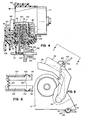
- a toy vehicle 10 such as a tow truck is disclosed in which an inertia flywheel drive mechanism 12 constructed in accordance with a preferred embodiment of this invention is incorporated.
- the inertia flywheel drive mechanism 12 comprises a generally cup-shaped preferably plastic housing 14 having an inner circular cover plate 16 secured thereto by nails 18 and/or screws.
- the housing 14 and cover plate 16 have axial bores within which bearings 20 are mounted for rotatably supporting a drive shaft 22.
- a drive gear 24 is mounted on the end of the drive shaft extending past the coverplate, and is keyed thereto by a flattened portion 26 of the shaft extending through a correspondingly shaped axial opening in the drive gear.
- the drive gear 24 is secured to drive shaft 22 by an end plate 28 pressed onto the drive gear and secured to the drive shaft by a detent 30.
- the mechansim for imparting rotation to drive shaft 22 and drive gear 24 comprises a stub shaft 32 having ratchet teeth 34 at one end thereof.
- the stub shaft 32 is journaled for rotation in an axial sleeve 36 on an outer cover plate 38 secured to housing 14 by nails 40 and/or screws.
- the opposite end of stub shaft 32 is preferably non-circular and extends into a corresponding opening in a crank 42.
- the crank is secured to stub shaft 32 by a screw 44.
- the stub shaft 32 is axially movable causing ratchet teeth 34 to engage ratchet teeth 46 on end plate 28 for imparting counter-clockwise rotation to drive shaft 22 and drive gear 24.upon rotation of crank 42. If desired, the ratchet teeth orientation can be reversed for imparting clockwise rotation to the drive shaft and gear.
- the inertia mechanism for imparting continued counter-clockwise rotation to drive shaft 22 and drive gear 24 after cranking is terminated will now be described.
- the inertia mechanism comprises a planetary gear system having a circular drive plate 48 secured to or integral with drive shaft 22.
- the plate has diametrically opposed, laterally extending spindles 50 for rotatably supporting planetary pinion gears 52.
- the gears 52 mesh with a ring gear 54 fixed to housing 14 by any suitable means.
- Gears 52 further mesh with an axially extending gear 56 integral with an intermediate drive plate 58 rotatably mounted on drive shaft 22.
- Drive plate 58 also has diametrically opposed, laterally extending spindles 60 for rotatably supporting pinion gears 62.
- Gears 62 also mesh with fixed ring gear 54 and an axially extending gear 64 integral with a circular preferably plastic cage 66 within which a cylindrical metal inertia flywheel 68 is secured. Accordingly, initial rotation of crank 42 in a counter-clockwise direction at a predetermined revolutions per minute (RPM) will impart, via the planetary gear system, rotation to the inertia flywheel 68 of a much higher RPM. When the cranking is discontinued, the inertia flywheel 68 continues its high velocity rotation for imparting through the planetary gear system continued rotation of drive shaft 22 and drive gear 24 in its counter-clockwise direction.
- RPM revolutions per minute
- the power generated by inertia flywheel 68 is transmitted by a pair of side-by-side gear transmissions to a winch drum 70 for pulling or releasing a load, and a wheel shaft 72 for driving the vehicle forward or reverse.
- the winch and wheel shaft gear transmissions as best seen in Figs. 2 and 4, comprise U-shaped winch and wheel shaft cradles 74, 76 respectively having laterally outwardly extending cylindrical flanges 78, 80 pivotal within axial openings in outer cover plate 38 and a wall 82 of housing 14.
- the cradles 74, 76 are in abutting relation and supported for relative pivotal movement on their abutting inner walls by a ring 84 on one cradle wall nesting within an annular groove 86 on the other cradle wall.
- the cradle flanges 78, 80 further have axially aligned hexagonal openings 88, 90 extending therethrough for receiving complementary hexagonal rings 92, 94 laterally extending from one of the ends of winch and drive wheel shift levers 96, 98 respectively. This joins the shift levers to the cradles such that pivotal movement of the shift levers will pivotally move the cradles relative to one another.
- the cradles 74, 76 partially encircle winch and wheel drive gears 100, 102 respectively which are rotatably mounted on a transmission shaft 104.
- the shaft extends through the center of shift lever rings 92, 94 and has a lock ring 106 at one end.
- the opposite end of shaft 104 has a head 108 and rotatably supports winch drum 70 having an axial stub shaft 112 journaled in the opening in shift lever ring 92.
- winch drum 70 and winch gear 100 The drive connection between winch drum 70 and winch gear 100 is achieved by a clutch comprising projections 114 on the end of the winch drum stub shaft 112 engaging complementary indentations 116 in an annular surface 118 on the core of winch gear 100.
- An expansion helical spring 120 mounted in an annular space between shaft 104 and winch drum 70 urges the hub projections 114 into engagement with the gear core indentations 116 with a predetermined friction force.
- winch drum 70 is prevented from rotating for any reason, the spring force is overcome and winch gear 100 will slip relative to drum 70.
- gear 122 The drive connection between wheel drive gear 102 and wheel shaft 72 is achieved by a gear 122 rotatably mounted on the wheel shaft and in meshing engagement with wheel drive gear 102.
- Gear 122 has laterally extending spring fingers 124 bearing against flat surfaces 126 of a non-circular clutch member 128 secured to wheel shaft 72 by a key or the like. If for any reason wheel shaft 72 is prevented from rotation, spring fingers 124 will flex allowing gear 122 to rotate relative to the wheel shaft.
- the cradles 74, 76 further rotatably support winch and drive wheel pinion gears 130, 132 in meshing engagement with the winch and drive wheel gears 100, 102 respectively.
- the pinion gears 130, 132 are rotatably mounted on shafts extending between and secured to the walls of the cradles.
- the winch pinion gear 130 as best seen in Fig. 2, is movable by cradle 74 and shift lever 96 into wind, unwind and neutral positions.
- the drive wheel pinion gear 132 (Fig. 4) is separately movable by cradle 76 and shift lever 98 into forward, reverse and neutral positions. In the winch wind position shown in full lines in Fig.
- winch pinion gear 130 meshes with drive gear 100 which drives winch hub (Fig. 4) in a counter-clockwise direction for winding a cord 110 attached thereto.
- pinion gear 130 meshes with a driven idler gear 138 in mesh with main drive gear 24 for driving winch drum 70 in a clockwise direction.
- Idler gear 138 is rotatably mounted on a shaft 140 (Fig. 2) journaled in bearings 142 on the inner and outer cover plates 16, 38 as best seen in Fig. 3.
- pinion gear 130 In the neutral position, pinion gear 130 is disengaged from the drive and idler gears 24, 138.
- a fixed gear tooth 144 extending laterally from cover plate 38 meshes with the pinion gear 130 for locking or braking the gear to prevent winch drum 70 from unwinding or free-wheeling if the winch drum is subjected to a torque due to a load on the winch cord.
- drive wheel pinion gear 132 (Fig. 4) meshes with drive gear 24 which drives drive wheel pinion gear 132 (Fig. 3), gear 102 and gear 122 for driving wheel shaft 72 and wheels 146 secured thereto in a clockwise direction for moving the vehicle in a reverse direction.
- drive wheel pinion gear 132 meshes with idler gear 138 for driving the vehicle through gears 102, 122 in a forward direction.
- drive wheel pinion gear 132 is disengaged from gears 24, 138 and is free to idle in the event the vehicle wheels 146 are rotated manually.
- Each of the cradle detent mechanisms comprises peripheral spaced grooves'148 on each of the cradles for receiving a spring lug 150 biased toward the cradles.
- the grooves 148 and lug 150 are arranged such that each time the lug bottoms in a groove, the cradles and pinion gears 130, 132 are precisely positioned in selected ones of the winch and drive wheel operating positions.
- a pair of stop posts 152, 154 are provided on housing 14 for limiting the range of pivotal movement of the cradles 74, 76 to prevent damage to or jamming of the cradles, pinion gears 130, 132, drive gears 100, 102 and idler gear 138.
- Each shift lever detent mechanism comprises a V-shaped projection 160 on the boom member adapted to nest in an elongated slot 162 in a semi-circular flange 164 extending from each shift lever 96, 98.
- a spring 166 interconnects the shift levers and urges them toward the projections 160.
- the shift lever force arm (distance between the shift lever pivot and point on the shift lever where force is applied to shift the lever) is considerably greater than the cradle detent force arm (distance between the cradle pivot and cradle detent grooves), it is easy for a child to move a shift lever past the cradle detent neutral position with little effort.
- the shift lever detents 160, 162 eliminate this problem since the child can feel and respond to the shift lever neutral position and not overshoot it.
- the precise positioning of the cradle and pinion gears 130, 132 is achieved, however, by the cradle detent mechanism 148, 150.
- winch drum 70 is provided with a non-circular hub 168 in which the periphery thereof has at least one radially extending shoulder 170.
- the winch drum cord 110 has one end secured to a hook 172 (Fig. 1) which can be secured to any suitable object that is to be pulled or lifted. Normally the intermediate portion of the cord passes over a pulley 174 supported at the free ends of the vehicle projecting boom members 156, 158.
- the other end of cord 110 has a loop 176, and the looped end encircles the hub with the intermediate portion of the cord threaded through the loop. When the cord tightens around the hub, the cord forms a knotl78 at the loop.
- the hub shoulder 170 engages the loop knot 178 and winds the cord around the hub.
- the winch shift lever is moved into its unwind position, the winch drum is driven in the opposite direction unwinding the cord and lowering the object.
- the hub shoulder slips over the knot upon continued unwinding rotation of the winch drum so that the cord is not wound onto the hub in the opposite direction. This assures that in the winch unwind position, no winding of the cord can take place.
Landscapes
- Toys (AREA)
Applications Claiming Priority (2)
| Application Number | Priority Date | Filing Date | Title |
|---|---|---|---|
| US06/346,163 US4428148A (en) | 1982-02-05 | 1982-02-05 | Inertia flywheel drive mechanism for a toy vehicle |
| US346163 | 1982-02-05 |
Publications (1)
| Publication Number | Publication Date |
|---|---|
| EP0086041A1 true EP0086041A1 (fr) | 1983-08-17 |
Family
ID=23358239
Family Applications (1)
| Application Number | Title | Priority Date | Filing Date |
|---|---|---|---|
| EP83300213A Withdrawn EP0086041A1 (fr) | 1982-02-05 | 1983-01-17 | Moteur à inertie pour véhicule-jouet |
Country Status (3)
| Country | Link |
|---|---|
| US (1) | US4428148A (fr) |
| EP (1) | EP0086041A1 (fr) |
| CA (1) | CA1197101A (fr) |
Family Cites Families (4)
| Publication number | Priority date | Publication date | Assignee | Title |
|---|---|---|---|---|
| US991275A (en) | 1909-05-06 | 1911-05-02 | David P Clark | Mechanically-operated toy. |
| DE694084C (de) | 1937-02-27 | 1940-07-25 | Heinrich Mueller | Spielzeugfederlaufwerk mit Umschalteinrichtung auf verschiedene Fahrtgeschwindigkeiten |
| DE1043176B (de) | 1957-06-29 | 1958-11-06 | Hans Mangold | Spielfahrzeug mit Schwungradantrieb |
| DE1092824B (de) | 1959-06-19 | 1960-11-10 | Hans Biller | Spielzeug mit Hebevorrichtung |
-
1982
- 1982-02-05 US US06/346,163 patent/US4428148A/en not_active Expired - Fee Related
- 1982-12-31 CA CA000418793A patent/CA1197101A/fr not_active Expired
-
1983
- 1983-01-17 EP EP83300213A patent/EP0086041A1/fr not_active Withdrawn
Non-Patent Citations (1)
| Title |
|---|
| No relevant documents have been disclosed. * |
Also Published As
| Publication number | Publication date |
|---|---|
| US4428148A (en) | 1984-01-31 |
| CA1197101A (fr) | 1985-11-26 |
Similar Documents
| Publication | Publication Date | Title |
|---|---|---|
| US4004780A (en) | Winch | |
| US4426064A (en) | Winch drive mechanism | |
| US4154121A (en) | Clutch mechanism | |
| US20020121633A1 (en) | Lifting gear | |
| JP4633719B2 (ja) | 自動変速装置 | |
| US4390161A (en) | Winch drive and brake mechanism | |
| CN1274324A (zh) | 自行车变速器用的开关 | |
| JPH0729754B2 (ja) | レバー式捲上機 | |
| US4428148A (en) | Inertia flywheel drive mechanism for a toy vehicle | |
| US4986400A (en) | Bi-directional spring clutch for reducing worm gear drive | |
| US5228661A (en) | Spare tire carrier and winch | |
| KR20060108526A (ko) | 마찰 클러치를 구비한 벨트 감김 장치 | |
| US3388617A (en) | Automatic variable speed bicycle transmission | |
| US4813299A (en) | Automatic transmission | |
| AU645997B2 (en) | Winch | |
| AU659368B1 (en) | Free-rotation control apparatus of hoist and traction machine | |
| US4226387A (en) | Multiplying fishing reel with level-wind carriage | |
| EP0744374A2 (fr) | Treuil à plusieurs rapports et pignont constamment en prise | |
| KR100944972B1 (ko) | 자동 속도변환장치의 브레이크장치 | |
| KR20060108525A (ko) | 후퇴 방지 클러치를 구비한 벨트 감김 장치 | |
| JPH065744Y2 (ja) | 魚釣用リールの駆動装置 | |
| RU2192385C1 (ru) | Лебедка | |
| JPS6338231Y2 (fr) | ||
| SU1627501A1 (ru) | Лебедка | |
| SU1087456A1 (ru) | Ручна волнова лебедка |
Legal Events
| Date | Code | Title | Description |
|---|---|---|---|
| PUAI | Public reference made under article 153(3) epc to a published international application that has entered the european phase |
Free format text: ORIGINAL CODE: 0009012 |
|
| AK | Designated contracting states |
Designated state(s): BE DE FR GB NL |
|
| 17P | Request for examination filed |
Effective date: 19840120 |
|
| STAA | Information on the status of an ep patent application or granted ep patent |
Free format text: STATUS: THE APPLICATION IS DEEMED TO BE WITHDRAWN |
|
| 18D | Application deemed to be withdrawn |
Effective date: 19850608 |
|
| RIN1 | Information on inventor provided before grant (corrected) |
Inventor name: STERN, CARL M. Inventor name: VENTRE, MICHAEL Inventor name: MAHER, WILLIAM M. |