EP0086054B1 - Industrieroboter, sowie Ausleger und Antriebssystem - Google Patents
Industrieroboter, sowie Ausleger und Antriebssystem Download PDFInfo
- Publication number
- EP0086054B1 EP0086054B1 EP83300373A EP83300373A EP0086054B1 EP 0086054 B1 EP0086054 B1 EP 0086054B1 EP 83300373 A EP83300373 A EP 83300373A EP 83300373 A EP83300373 A EP 83300373A EP 0086054 B1 EP0086054 B1 EP 0086054B1
- Authority
- EP
- European Patent Office
- Prior art keywords
- axis
- drive
- drive unit
- arm
- gear
- Prior art date
- Legal status (The legal status is an assumption and is not a legal conclusion. Google has not performed a legal analysis and makes no representation as to the accuracy of the status listed.)
- Expired
Links
Images




Classifications
-
- B—PERFORMING OPERATIONS; TRANSPORTING
- B25—HAND TOOLS; PORTABLE POWER-DRIVEN TOOLS; MANIPULATORS
- B25J—MANIPULATORS; CHAMBERS PROVIDED WITH MANIPULATION DEVICES
- B25J19/00—Accessories fitted to manipulators, e.g. for monitoring, for viewing; Safety devices combined with or specially adapted for use in connection with manipulators
- B25J19/0025—Means for supplying energy to the end effector
- B25J19/0029—Means for supplying energy to the end effector arranged within the different robot elements
-
- B—PERFORMING OPERATIONS; TRANSPORTING
- B25—HAND TOOLS; PORTABLE POWER-DRIVEN TOOLS; MANIPULATORS
- B25J—MANIPULATORS; CHAMBERS PROVIDED WITH MANIPULATION DEVICES
- B25J17/00—Joints
- B25J17/02—Wrist joints
- B25J17/0241—One-dimensional joints
-
- B—PERFORMING OPERATIONS; TRANSPORTING
- B25—HAND TOOLS; PORTABLE POWER-DRIVEN TOOLS; MANIPULATORS
- B25J—MANIPULATORS; CHAMBERS PROVIDED WITH MANIPULATION DEVICES
- B25J17/00—Joints
- B25J17/02—Wrist joints
- B25J17/0283—Three-dimensional joints
-
- B—PERFORMING OPERATIONS; TRANSPORTING
- B25—HAND TOOLS; PORTABLE POWER-DRIVEN TOOLS; MANIPULATORS
- B25J—MANIPULATORS; CHAMBERS PROVIDED WITH MANIPULATION DEVICES
- B25J19/00—Accessories fitted to manipulators, e.g. for monitoring, for viewing; Safety devices combined with or specially adapted for use in connection with manipulators
- B25J19/0008—Balancing devices
- B25J19/002—Balancing devices using counterweights
-
- B—PERFORMING OPERATIONS; TRANSPORTING
- B25—HAND TOOLS; PORTABLE POWER-DRIVEN TOOLS; MANIPULATORS
- B25J—MANIPULATORS; CHAMBERS PROVIDED WITH MANIPULATION DEVICES
- B25J9/00—Program-controlled manipulators
- B25J9/02—Program-controlled manipulators characterised by movement of the arms, e.g. cartesian coordinate type
- B25J9/04—Program-controlled manipulators characterised by movement of the arms, e.g. cartesian coordinate type by rotating at least one arm, excluding the head movement itself, e.g. cylindrical coordinate type or polar coordinate type
- B25J9/046—Revolute coordinate type
-
- B—PERFORMING OPERATIONS; TRANSPORTING
- B25—HAND TOOLS; PORTABLE POWER-DRIVEN TOOLS; MANIPULATORS
- B25J—MANIPULATORS; CHAMBERS PROVIDED WITH MANIPULATION DEVICES
- B25J9/00—Program-controlled manipulators
- B25J9/08—Program-controlled manipulators characterised by modular constructions
-
- B—PERFORMING OPERATIONS; TRANSPORTING
- B25—HAND TOOLS; PORTABLE POWER-DRIVEN TOOLS; MANIPULATORS
- B25J—MANIPULATORS; CHAMBERS PROVIDED WITH MANIPULATION DEVICES
- B25J9/00—Program-controlled manipulators
- B25J9/10—Program-controlled manipulators characterised by positioning means for manipulator elements
- B25J9/102—Gears specially adapted therefor, e.g. reduction gears
-
- B—PERFORMING OPERATIONS; TRANSPORTING
- B25—HAND TOOLS; PORTABLE POWER-DRIVEN TOOLS; MANIPULATORS
- B25J—MANIPULATORS; CHAMBERS PROVIDED WITH MANIPULATION DEVICES
- B25J9/00—Program-controlled manipulators
- B25J9/10—Program-controlled manipulators characterised by positioning means for manipulator elements
- B25J9/104—Program-controlled manipulators characterised by positioning means for manipulator elements with cables, chains or ribbons
- B25J9/1045—Program-controlled manipulators characterised by positioning means for manipulator elements with cables, chains or ribbons comprising tensioning means
-
- B—PERFORMING OPERATIONS; TRANSPORTING
- B25—HAND TOOLS; PORTABLE POWER-DRIVEN TOOLS; MANIPULATORS
- B25J—MANIPULATORS; CHAMBERS PROVIDED WITH MANIPULATION DEVICES
- B25J9/00—Program-controlled manipulators
- B25J9/10—Program-controlled manipulators characterised by positioning means for manipulator elements
- B25J9/12—Program-controlled manipulators characterised by positioning means for manipulator elements electric
- B25J9/126—Rotary actuators
-
- H—ELECTRICITY
- H02—GENERATION; CONVERSION OR DISTRIBUTION OF ELECTRIC POWER
- H02K—DYNAMO-ELECTRIC MACHINES
- H02K16/00—Machines with more than one rotor or stator
-
- H—ELECTRICITY
- H02—GENERATION; CONVERSION OR DISTRIBUTION OF ELECTRIC POWER
- H02K—DYNAMO-ELECTRIC MACHINES
- H02K37/00—Motors with rotor rotating step by step and without interrupter or commutator driven by the rotor, e.g. stepping motors
-
- Y—GENERAL TAGGING OF NEW TECHNOLOGICAL DEVELOPMENTS; GENERAL TAGGING OF CROSS-SECTIONAL TECHNOLOGIES SPANNING OVER SEVERAL SECTIONS OF THE IPC; TECHNICAL SUBJECTS COVERED BY FORMER USPC CROSS-REFERENCE ART COLLECTIONS [XRACs] AND DIGESTS
- Y10—TECHNICAL SUBJECTS COVERED BY FORMER USPC
- Y10T—TECHNICAL SUBJECTS COVERED BY FORMER US CLASSIFICATION
- Y10T74/00—Machine element or mechanism
- Y10T74/19—Gearing
- Y10T74/19023—Plural power paths to and/or from gearing
- Y10T74/19051—Single driven plural drives
- Y10T74/19065—Aligned
Definitions
- the present invention relates to an industrial robot of the type designed as a replacement for human labor in performing repetitive, hazardous, or tiring work.
- Industrial robots of the described type typically have the capability of moving through six revolute axes to manipulate objects, parts, or tools through variable programmed motions for the performance of a variety of tasks.
- Reprogrammable robots are also available which incorporate a computer and microprocessor whereby the robot may be taught to move from point to point using a portable teaching box or the like.
- a first drive module consists of a motor, a brake and an odometer.
- the motor shaft is connected, via a swivel fork, to a second drive module, comprising a motor, a brake, and odometer.
- a connecting flange rotated by the shaft of motor and connected to a third drive module comprising a motor, brake and odometer.
- the shaft of the third motor is connected to an end piece.
- the shafts of the three drive modules are mutually perpendicular.
- the rotation of the motor of the first drive module rotates, via the fork and connecting flange, the other two drive modules about an axis X.
- the rotation of the second motor causes the third module to rotate about an axis Y, and a third direction Z for the end piece is directly obtained from the rotation of the motor of the third module.
- the end piece can be moved by the rotary motions of the three motors in the directions X, Y and Z.
- the power can be supplied to the second and third drive modules through a hollow shaft, the third drive module being connected via tubular and rotating elements.
- FR-A-1 266080 discloses an electrically remotely controlled manipulator which comprises two identical electric devices, one serving as a transmitter and the other as a receiver. Each comprises four "selsyns" arranged in an identical manner.
- Mounted on a carriage moving on rails is a first motor with a shaft axis perpendicular to the carriage.
- a bracket on the shaft carries a second motor having a shaft axis perpendicular to that of the first motor.
- Mounted on the second motor shaft is a third motor having a shaft perpendicular to the second motor shaft.
- a fourth motor actuates the transmission of the carriage, which transforms the rotary motion of the fourth motor to a rectilinear movement.
- Each transmitter motor connects with the corresponding receiver motor so that motion of the transmitter motors is reproduced by the receiver motor.
- a gripping device is mounted on the end of the shaft of the third motor of the receiver, which follows movements of a control mounted on the third motor shaft of the transmitter.
- DE-A-2 228 598 discloses an anthropomorphic manipulator which consists of a torso, arms with hands, and legs with feet, or only of two arms with hands and a pair of shoulders, or only of one shoulder, one arm with one hand.
- the individual limbs are connected by joints which allow variation of the angular position of the limbs and/or relative rotation.
- Such a joint is enclosed in a hollow, preferably cylindrical capsule with preferably two flat bottoms rotatable in opposite directions.
- Contained in the capsule are a motor, which effects movements of the limbs, a transmission, a hollow driven shaft terminating on one side in a flange, and which extends through the transmission, the motor and its shaft and through the capsule bottom.
- a measuring device measures the angle which is formed by the one limb attached on the side of the flange with the other limb on the side of the capsule bottom.
- the motor shaft, drive shaft and driven shafts, the shaft of the angle measuring device and the cylinder axis of the joint capsule are coaxial.
- an industrial robot having at least three separately controlled axes of movement, and in which drives for two of the movements have coaxial components, and comprises a support member, a first drive unit having a base component fixedly mounted to said support member, and a secondary component rotatably mounted with respect to said base component to define a first axis (A), and drive means for relatively rotating said base component and secondary component about said first axis (A), a second drive unit having a base component, and a secondary component rotatably mounted with respect to its base component to define a second axis (B), means fixedly mounting said secondary component of said second drive unit to said secondary component of said first drive unit such that the second axis (B) is non parallel to said first axis (A), output means fixed to said base component of said second drive unit and aligned coaxially with said second axis (B), and drive means for relatively rotating said base component and secondary component of said second drive unit about said second axis (B), a third drive unit having a base component and a secondary
- a modular industrial robot which comprises first, second, and third drive units of like construction, and which are adapted to move the robot about its three primary axes of movement.
- Each drive unit includes a base component and a secondary component which is rotatable with respect to the base component, and with the base component including a mounting flange.
- a coupler is provided for releasably connecting each of the mounting flanges to a mating flange on an external member, such as a support stand or output shaft.
- the secondary components of all three of the drive units are releasably interconnected to each other, whereby the robot may be configured to have one, two, or all three of the drive units.
- the coupler for connecting the mounting flange of the drive units to the external member comprises a V-shaped split band which is adapted to enclose the periphery of the adjacent flanges when they are disposed in a mating, contiguous relation so as to maintain the assembly thereof.
- the base component of the first component will be coupled to a support stand so as to define a first axis
- the second and third drive units will be interconnected to the secondary component of the first drive unit and so as to be coaxially disposed about a second axis which is perpendicular to and intersects the first axis.
- the robot includes an inner arm which is connected to one of the drive units by a similar V-band coupler, and an outer arm which is pivotally connected to the inner arm by still another V-band coupler.
- the outer arm may be selectively removed from its connection with the inner arm and then mounted to the drive unit which initially mounted the inner arm, or alternatively, the outer arm may be mounted directly to the support stand.
- the illustrated robot includes three primary axes of movement, with the drive unit for each of the movements being substantially identical to each other.
- Each such drive unit comprises an electric stepping motor and brake, and the outputs of the motor and brake are mounted parallel to each other and are operatively connected to a gear wheel disposed coaxially about the moveable axis of the drive unit.
- the robot of the embodiment also includes a three axis outer arm assembly, which includes an outer hand assembly, and three cocnentric tubular members having suitable interconnecting gears for operating the hand assembly for movement about its three axes.
- the tubular members are each selectively rotatable by a separate electric stepping motor mounted adjacent the end of the outer arm assembly opposite the hand assembly.
- at least two of the tubular members are preferably mounted so as to permit limited axial movement, and spring biasing means is provided for biasing the axially movable tubular members so as to insure proper meshing engagement of the gears and to compensate for any wear thereof.
- the gear train from each stepping motor to each tubular member has the same gear ratio, to thereby facilitate and simplify the control of the stepping motors.
- the preferred embodiment of the invention also includes a novel drive arrangement for the inner and outer arms, which permits precisely controllable relative movement between the two arms.
- the drive arrangement includes a flexible endless toothed belt mounted between input and output sprockets, and means for contacting and deflecting each run of the conveyor belt so as to deflect the runs in equal amounts and in opposite directions, to thereby permit the belt to be maintained in a tensioned condition and substantially avoid backlash, and while also avoiding relative rotation between the input and output shafts upon adjustment of the tension in the belt.
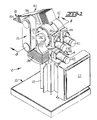
- a robot embodying the features of the present invention is indicated generally at 10.
- the robot is adapted to move through six revolute axes, and it comprises a main frame 12 which includes a support stand 13, with the stand defining a generally vertical axis A in the illustrated embodiment.
- a waist 14 is rotatable with respect to the stand and defines a generally horizontal axis B, which is perpendicular to and intersects the axis A.
- a first or inner arm 15 is rotatable with respect to the waist about the horizontal axis B, and a second or outer arm 16 is rotatable with respect to the inner arm about a second horizontal axis C, which is parallel to and laterally spaced from the axis B.
- a hand assembly 18 including a gripper 19 is mounted at one end of the outer arm, and is adapted to move through three additional axes of movement as further described below.
- the main frame of the robot includes a control box 20 mounted to the frame adjacent the stand 13 for housing the electronic controls for the various drive motors of the robot.
- the robot 10 further includes a first drive unit 21 having a tubular base component 21a and a secondary component 21 b which is rotatable with respect to the base component about the axis A.
- the base component 21a is releasably connected to the support stand 13 by coupling means which includes a circular flange 24 on the support stand, and a mating circular flange 21 c integrally formed on the base component, with the two flanges 21c, 24 being of like diameter and cross sectional configuration.
- the coupling means further includes a releasable coupler 25 in the form of a split band of generally V-shaped configuration which is adapted to enclose the periphery of the mating flanges when they are placed in abutting relation.
- the split band incorporates a release mechanism 26 (note Figure 16) comprising a threaded shaft and nut, for selectively opening and tightening the band circumferentially about the periphery of the abutting flanges, and so as to selectively retain the flanges in assembled relation.
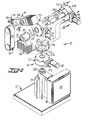
- a ring-like carriage 28 is mounted to the secondary component 21 b of the first drive unit 21, and the carriage in turn mounts a second drive unit 22 and a third drive unit 23 which collectively form a part of the waist 14 of the robot.
- the units are of substantially identical configuration, and this standardization of drive units greatly simplifies the design, construction, and repair of the overall apparatus, and promotes the interchangeability of parts.
- the second and third drive units 22, 23 each include a tubular base component 22a, 23a having a mounting flange 22c, 23c at one end, and a secondary component 22b, 23b which is relatively rotatable about the axis of its base component.
- the secondary components 22b, 23b are fixed to each other and to the carriage 28 by removable bolts 30 or the like, and such that the second and third drive units are coaxially disposed about the axis B. Also, the second and third drive units are disposed in opposite orientations as will be apparent from Figure 5.
- a tubular extension 32 is releasably connected to the base component 23a of the third drive unit 23 by coupling means, which includes a circular flange 33 at one end of the extension and which mates with the flange 23c on the base component of the drive unit.
- the abutting flanges are releasably coupled by a V-band coupler 25 of a construction corresponding to that joining the flanges 21c and 24 at the support stand.
- the tubular extension 32 includes a second flange 35 at its other end for the purposes to be described.
- the extension mounts a number of weights 36 which serve to counterbalance the weight of the outer arm 16 during the movement about the axis B.
- the base component 22a of the second drive unit 22 mounts an elongate drive shaft 38 which extends coaxially through the base component 23a of the third drive unit and extension 32.
- the drive shaft 38 includes a flange 39 at one end which is releasably joined to the flange 22c of the base component of the second drive unit by another coupler 25.
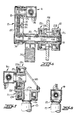
- FIGS. 3 and 4 illustrate the second drive unit 22 in more detail, and which is also representative of the first and third drive units.
- the drive unit 22 comprises a pair of electric drive members 42, 44 fixed to the secondary component 22b of the unit.
- the member 42 is in the form of an electric stepping motor, and the member 44 is in the form of a conventional electromagnetic brake.
- the output shafts of the members are disposed parallel to each other, and each mounts a drive gear 46.
- a pinion gear 48 is rotatably mounted to the secondary component and is positioned to operatively mesh with each of the drive gears 46.
- a shaft 49 extends coaxially from the pinion gear and mounts an output gear 50, which is positioned to mesh with the face gear 51 of the gear wheel 52, with the gear wheel being fixed to the base component 22a coaxially about the axis A.
- the face gear 51 is in the form of a circular rack, i.e., the faces of the gear teeth are co-planar and lie in a plane perpendicular to its rotational axis. This configuration facilitates the alignment and assembly of the output gear 50 with the face gear 51, since alignment along only a single direction is required, rather than a plurality of directions as would be required by conventional bevel gears.
- Electrical stepping motors are per se well known in the art and are operated by discrete electrical pulses which are fed in a sequential manner from a suitable switching control system. For every pulse fed to the motor, the motor rotates a fixed angle, typically 1.8 degrees. Thus the number fed to the motor determines the rotational angle the motor will make. In order to obtain verification that the motor has in fact rotated, it is also common to mount a shaft encoder on the output shaft of the motor, which produces a verification signal upon each step having been taken.
- the drive control for the motor 42 and brake 44 is schematically illustrated in Figure 3, and includes a suitable switching apparatus or pulse generator 55, which is operatively connected to the motor.
- the operation of the generator 55 is controlled by a program 56 of a digital computer or the like.
- the shaft encoder 57 feeds a verification signal to a comparator 58 upon each rotational step of the motor. Should the comparator detect a failure of rotation, a suitable corrective signal is fed to the generator.
- the program also controls operation of the brake 44, to actuate the brake whenever the motor is inoperative.
- the secondary component 22b of the drive unit may also mount a pair of limit switches 60, 61 as illustrated schematically in Figure 3.
- the limit switches serve as safety switches to limit the angular movement of the base member 22a with respect to the secondary member 23b. More particularly, the switches are closed by engagement with a stop 65 positioned on the inner side of face gear 51, and upon closure of either switch of the pair, the brake 44 is actuated to preclude further rotation.
- a positive abutment 66 is also shown mounted on the secondary member 22b downstream of each of the switches, whcih is designed to be positively engaged by the stop 65 and provide absolute protection against excessive relative rotation in the event the adjacent switch should fail.
- the inner arm 15 of the robot comprises a casing 70, which has a mounting flange 71 at one end which is releasably connected to the flange 35 of the extension 32 by still another coupler 25, which also conforms to the structure of the other couplers utilized on the robot.
- the shaft 38 from the second drive unit extends coaxially through the flange 71 of the casing, and mounts a sprocket 74 at the free end thereof.
- a second shaft 75 is rotatably mounted at the other end of the casing 70, and is disposed coaxially about the horizontal axis C, which is parallel to and laterally spaced from the horizontal axis B.
- the shaft 75 includes an integral flange 76 which mates with a flange 77 on the casing 78 of the outer arm 16, and the two flanges are joined by a further V-band coupler 25.
- the second shaft 75 mounts a sprocket 81 within the casing 70 of the inner arm, and a flexible endless toothed belt 82 is operatively entrained about the sprockets.
- the adjustment means includes a pivot arm 84 mounted within the casing 70 of the inner arm for pivotal movement about a pin 85 which defines an axis which is positioned between and parallel to the axes B and C. Also, the rotational axis of the pin 85 is positioned to intersect a line extending perpendicularly between the axes B and C.
- a roller 86 is mounted at each end of the pivot arm, and an adjustable linkage 87 interconnects the pivot arm and the casing of the inner arm, whereby the pivot arm may be positioned such that the rollers 86 contact the outside surface of the belt on respective runs thereof.
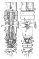
- the outer arm 16 of the robot is best seen in Figures 9 and 10, and includes the hand assembly 18 and gripper 19 mounted at one end, and three
- the hand assembly includes a frame member 94, a transverse wrist pin 95 mounted to the frame member, and a wrist rotary member 96 rotatably mounted with respect to said frame member 94.
- the gripper 19 is mounted to the wrist rotary member, with the fingers of the gripper being movable in either the opening or closing direction by separate air pressure lines as further described below.
- the casing 78 of the outer arm 16 supports three coaxially disposed and relatively rotatable tubular members 98, 99, 100, for transmitting the desired movements to the components of the hand assembly from the respective drive motors 90, 91, 92. More particularly, there is provided a first tubular member 98 which is rotatably supported in the casing 78 by bearings, and which includes a yoke 102 at the outer end which mounts the transverse wrist pin 95.
- first tubular member 98 which is rotatably supported in the casing 78 by bearings, and which includes a yoke 102 at the outer end which mounts the transverse wrist pin 95.
- the second tubular member 99 is rotatably supported coaxially within the first member by bearings, and it includes a bevel gear 104 at its outer end.
- the bevel gear 104 meshes with a gear 105 which is disposed about the axis of the wrist pin 95 and which is fixed to the frame member 94 of the hand assembly.
- rotation of the second tubular member 99 causes the frame member 94 to pivot about the axis of the wrist pin, commonly referred to as "wrist flex.”
- the third tubular member 100 is rotatably mounted coaxially within the second member, and it also includes a bevel gear 107 at the outer end thereof.
- the bevel gear 107 meshes with an idler gear 108 rotatably mounted about the axis of the wrist pin, and which in turn m'eshes with a bevel gear 109 on the end of the wrist rotary member.
- rotation of the third tubular member 100 causes the wrist rotary member to rotate with respect to the frame member, commonly referred to as "hand rotation.”
- the second and third tubular members 99, 100 are each mounted so as to permit limited axial movement thereof with respect to the first tubular member and casing, and a biasing annular wave spring 110 is mounted at the rear end of these members for resiliently urging the members in a direction toward the hand assembly, to thereby assure proper meshing of the associated bevel gears and to compensate for any wear thereof.
- the three drive.motors 90, 91, 92 of the outer arm are adapted to selectively rotate each of the first, second, and third tubular members about the central axis thereof, and relative to each other.
- the drive motors are operatively connected to respective tubular members by a gear train which includes an output gear 113 fixed to the output shaft of the associated motor, and a transmission rod 114 having one gear 115 meshing with the output gear 113 and a second gear 116 meshing with a gear 118 fixed to the end of the associated tubular member.
- the three gear trains have the same gear ratio, to thereby facilitate and simplify the control of the stepping motors, note Figure 13.
- Figure 11 illustrates in more detail the pneumatic system for actuating both the opening and closing of the gripper at the end of the outer arm 16.
- the system includes a rotary union 120 positioned within the wrist rotary member 96 of the hand assembly, a second rotary union 122 mounted within the tubular member 100, and a pair of flexible hoses 123, 124 extending between the two unions.
- the rotary union 120 is fixed to a sleeve 126, which in turn is mounted to the wrist pin 95.
- the rotary union 122 is fixed to a second sleeve 127, which also is mounted to the wrist pin.
- both of the rotary unions rotate with the wrist pin.
- a pair of coaxial rigid tubes 129, 130 which extend from rotary union 122 through the end plate 131 of the arm.
- the outer ends of the tubes are mounted to a coupler 132 by which two separate air lines may be connected to the two air passages defined by the coaxial tubes 129,130.
- the inner ends of these tubes are rotatably received in the union 122.
- a second pair of rigid tubes 134, 135 are fixed to the end block of the wrist rotary member 96 and are rotatably joined to the union 120 in the hand assembly.
- the two passages defined by the tubes 134, 135 communicate with respective ducts 137, 138 in the end block, which in turn lead to the gripper through the flexible hoses 140, 141.
- the gripper itself is generally conventional, and is adapted to close upon a workpiece upon air pressure being received through one line, and to open to release the workpiece upon air pressure being received through the other line.
- Figure 12 illustrates a modified and somewhat simplified configuration for the outer arm 16, which may be utilized where only wrist rotation and wrist flex are necessary.
- the third or innermost tubular member 100 has been removed, together with the idler gear 108 and end portion of the wrist rotary member 96, and motor 92.
- the arm is otherwise structurally the same as described above with reference to Figures 9-11.
- a further significant feature of the above described robot is the fact that it is essentially modular in nature, and it may be configured to serve a variety of specific applications.
- the use of the commonly structured coupling means between the various components of the robot greatly facilitates its reconfiguration.
- the robot is configured for movement about all of its six potential axes of movement.
- the first drive unit 21 has been removed, and the secondary components of the second and third drive units have been directly connected to a fixed support 144 by means of suitable bolts.
- This arrangement permits operation about five axes of movement.
- the support 144 and thus the robot may be disposed in any orientation so as to extend for example from a floor, a vertical side wall, or a ceiling.
- the third drive unit with the outer arm 16 attached thereto in the manner shown in Figure 7, could be disconnected from the carriage 28 and the first drive unit 21, and mounted directly to the support 144 or other suitable mounting structure.
Landscapes
- Engineering & Computer Science (AREA)
- Robotics (AREA)
- Mechanical Engineering (AREA)
- Power Engineering (AREA)
- Manipulator (AREA)
Claims (22)
Priority Applications (1)
| Application Number | Priority Date | Filing Date | Title |
|---|---|---|---|
| AT83300373T ATE31043T1 (de) | 1982-02-05 | 1983-01-25 | Industrieroboter, sowie ausleger und antriebssystem. |
Applications Claiming Priority (4)
| Application Number | Priority Date | Filing Date | Title |
|---|---|---|---|
| US346222 | 1982-02-05 | ||
| US06/346,222 US4424473A (en) | 1982-02-05 | 1982-02-05 | Drive apparatus for an industrial robot |
| US06/443,156 US4636138A (en) | 1982-02-05 | 1982-11-19 | Industrial robot |
| US443156 | 1989-11-30 |
Publications (3)
| Publication Number | Publication Date |
|---|---|
| EP0086054A2 EP0086054A2 (de) | 1983-08-17 |
| EP0086054A3 EP0086054A3 (en) | 1983-11-30 |
| EP0086054B1 true EP0086054B1 (de) | 1987-11-25 |
Family
ID=26994761
Family Applications (1)
| Application Number | Title | Priority Date | Filing Date |
|---|---|---|---|
| EP83300373A Expired EP0086054B1 (de) | 1982-02-05 | 1983-01-25 | Industrieroboter, sowie Ausleger und Antriebssystem |
Country Status (3)
| Country | Link |
|---|---|
| US (1) | US4636138A (de) |
| EP (1) | EP0086054B1 (de) |
| DE (1) | DE3374671D1 (de) |
Families Citing this family (64)
| Publication number | Priority date | Publication date | Assignee | Title |
|---|---|---|---|---|
| US4552505A (en) * | 1982-11-19 | 1985-11-12 | American Robot Corporation | Industrial robot having direct coaxial motor drive |
| US4645409A (en) * | 1982-02-05 | 1987-02-24 | American Cimflex Corporation | Outer arm assembly for industrial robot |
| JPS6036192U (ja) * | 1983-08-18 | 1985-03-12 | シルバー精工株式会社 | 産業用ロボット |
| JPS6130396A (ja) * | 1984-07-23 | 1986-02-12 | フアナツク株式会社 | 工業用ロボツトの交換可能腕構造 |
| CA1245246A (en) * | 1984-07-27 | 1988-11-22 | John Garin | Scara type manipulator apparatus |
| WO1986000846A1 (fr) * | 1984-07-27 | 1986-02-13 | Fanuc Ltd | Robot industriel a structure de bras creuse |
| US5201630A (en) * | 1984-09-07 | 1993-04-13 | Sony Corporation | Industrial robot with servo system |
| DE3447701A1 (de) * | 1984-12-28 | 1986-07-10 | Kuka Schweissanlagen + Roboter Gmbh, 8900 Augsburg | Industrie-roboter fuer unterschiedliche einsatzzwecke |
| GB2171074B (en) * | 1985-02-19 | 1988-04-20 | Litton Uk Ltd | Improvements in robot arms |
| JPS61249286A (ja) * | 1985-04-27 | 1986-11-06 | フアナツク株式会社 | 産業用ロボツト |
| JPS6263078A (ja) * | 1985-09-11 | 1987-03-19 | フアナツク株式会社 | 工業用ロボツトにおけるモジユ−ル方式 |
| FR2597388B1 (fr) * | 1986-04-18 | 1992-06-12 | Telemecanique Electrique | Dispositif d'entrainement d'une tete active de bras de robot. |
| DE3631024A1 (de) * | 1986-09-09 | 1988-03-17 | Mannesmann Ag | Roboterarm |
| US4813845A (en) * | 1987-03-16 | 1989-03-21 | Advanced Control Engineering, Inc. | Object transport apparatus |
| JP2591968B2 (ja) * | 1987-12-28 | 1997-03-19 | 株式会社日立製作所 | 産業用ロボットの手首 |
| DE3939836A1 (de) * | 1988-12-02 | 1990-06-07 | Tokico Ltd | Industrieroboter |
| US5102280A (en) * | 1989-03-07 | 1992-04-07 | Ade Corporation | Robot prealigner |
| DE4001885A1 (de) * | 1990-01-23 | 1991-07-25 | Kuka Schweissanlagen & Roboter | Mehrachsiger industrieroboter |
| IT1251017B (it) * | 1991-05-21 | 1995-04-28 | Ugo Crippa | Meccanismo per compiere traiettorie prefissate assimilabili ad ellittiche |
| US6731988B1 (en) | 1992-01-21 | 2004-05-04 | Sri International | System and method for remote endoscopic surgery |
| EP1356781A3 (de) | 1992-01-21 | 2013-07-24 | SRI International | Ferngesteuertes chirurgisches System |
| US6963792B1 (en) * | 1992-01-21 | 2005-11-08 | Sri International | Surgical method |
| US6788999B2 (en) | 1992-01-21 | 2004-09-07 | Sri International, Inc. | Surgical system |
| JP3465850B2 (ja) * | 1993-04-28 | 2003-11-10 | 株式会社安川電機 | 産業用ロボットの手首機構 |
| EP0699053B1 (de) * | 1993-05-14 | 1999-03-17 | Sri International | Chirurgiegerät |
| DE69635050T2 (de) | 1995-06-07 | 2006-05-24 | Sri International, Menlo Park | Chirurgischer manipulator für ein ferngesteuertes robotersystem |
| US5649956A (en) | 1995-06-07 | 1997-07-22 | Sri International | System and method for releasably holding a surgical instrument |
| US5814038A (en) | 1995-06-07 | 1998-09-29 | Sri International | Surgical manipulator for a telerobotic system |
| DE19608843C2 (de) * | 1996-03-07 | 1998-01-29 | Koera Verpackungsmaschinen | Roboter |
| IT1292275B1 (it) * | 1997-04-23 | 1999-01-29 | Comau Spa | Polso di robot industriale, e robot comprendente tale polso. |
| US6493608B1 (en) * | 1999-04-07 | 2002-12-10 | Intuitive Surgical, Inc. | Aspects of a control system of a minimally invasive surgical apparatus |
| DE10032098C2 (de) * | 2000-07-01 | 2003-06-05 | Kuka Roboter Gmbh | Roboterarm |
| US20060178556A1 (en) | 2001-06-29 | 2006-08-10 | Intuitive Surgical, Inc. | Articulate and swapable endoscope for a surgical robot |
| US6817974B2 (en) | 2001-06-29 | 2004-11-16 | Intuitive Surgical, Inc. | Surgical tool having positively positionable tendon-actuated multi-disk wrist joint |
| EP2359768B1 (de) | 2002-12-06 | 2018-10-03 | Intuitive Surgical Operations, Inc. | Flexibles Gelenk für ein Operationsinstrument |
| CA2615130A1 (en) * | 2005-07-26 | 2007-02-08 | Ams Research Corporation | Methods and systems for treatment of prolapse |
| EP2732344B1 (de) | 2011-07-11 | 2019-06-05 | Board of Regents of the University of Nebraska | Robotisches chirurgisches system |
| EP3730031A1 (de) | 2011-10-03 | 2020-10-28 | Board of Regents of the University of Nebraska | Robotische chirurgische vorrichtungen und systeme |
| CN103121215A (zh) * | 2011-11-18 | 2013-05-29 | 鸿富锦精密工业(深圳)有限公司 | 机器人臂部件 |
| EP2844181B1 (de) | 2012-05-01 | 2021-03-10 | Board of Regents of the University of Nebraska | Robotische einzelstandortvorrichtung sowie entsprechende systeme |
| US9010214B2 (en) | 2012-06-22 | 2015-04-21 | Board Of Regents Of The University Of Nebraska | Local control robotic surgical devices and related methods |
| US12295680B2 (en) | 2012-08-08 | 2025-05-13 | Board Of Regents Of The University Of Nebraska | Robotic surgical devices, systems and related methods |
| CA2880622C (en) | 2012-08-08 | 2021-01-12 | Board Of Regents Of The University Of Nebraska | Robotic surgical devices, systems and related methods |
| CA2906672C (en) | 2013-03-14 | 2022-03-15 | Board Of Regents Of The University Of Nebraska | Methods, systems, and devices relating to force control surgical systems |
| CA2918531A1 (en) | 2013-07-17 | 2015-01-22 | Board Of Regents Of The University Of Nebraska | Robotic surgical devices, systems and related methods |
| WO2016077478A1 (en) | 2014-11-11 | 2016-05-19 | Board Of Regents Of The University Of Nebraska | Robotic device with compact joint design and related systems and methods |
| CN108472030B (zh) | 2015-08-03 | 2021-06-18 | 内布拉斯加大学董事会 | 机器人手术装置系统及相关方法 |
| ITUB20159345A1 (it) * | 2015-12-23 | 2017-06-23 | Comau Spa | Robot industriale multi-asse, in particolare di tipo SCARA |
| US10751136B2 (en) | 2016-05-18 | 2020-08-25 | Virtual Incision Corporation | Robotic surgical devices, systems and related methods |
| EP3481598B1 (de) * | 2016-07-07 | 2020-09-02 | ABB Schweiz AG | Fundament für einen parallelkinematikroboter |
| WO2018045036A1 (en) | 2016-08-30 | 2018-03-08 | Board Of Regents Of The University Of Nebraska | Robotic device with compact joint design and an additional degree of freedom and related systems and methods |
| JP2018089739A (ja) * | 2016-12-02 | 2018-06-14 | 日本電産サンキョー株式会社 | 産業用ロボット |
| EP3687370B1 (de) | 2017-09-27 | 2024-11-20 | Virtual Incision Corporation | Robotische chirurgische vorrichtungen mit verfolgungskameratechnologie und verwandte systeme |
| WO2019136360A1 (en) * | 2018-01-05 | 2019-07-11 | Board Of Regents Of The University Of Nebraska | Single-arm robotic device with compact joint design and related systems and methods |
| JP6875348B2 (ja) * | 2018-10-17 | 2021-05-26 | ファナック株式会社 | ロボットおよび第1アーム部材 |
| CN114302665B (zh) | 2019-01-07 | 2025-12-19 | 虚拟切割有限公司 | 机器人辅助手术系统以及相关装置和方法 |
| DE102019108767A1 (de) | 2019-01-11 | 2020-07-16 | Hti Bio-X Gmbh | Greifvorrichtung zum Greifen von Deckeln für Laborgefäße |
| US11691270B2 (en) * | 2019-07-31 | 2023-07-04 | Sanctuary Cognitive Systems Corporation | Mechanism with three degrees-of-freedom (DOF) output to provide independent control over roll, pitch, and yaw of output structure |
| WO2022134513A1 (zh) * | 2020-12-22 | 2022-06-30 | 辰星(天津)自动化设备有限公司 | 一种可拓展机器人单元及六臂机器人 |
| US12552048B2 (en) | 2021-06-11 | 2026-02-17 | Magswitch Automation Company | Component handling systems and methods |
| EP4341049A4 (de) | 2021-06-11 | 2025-03-12 | Magswitch Technology, Inc. | Werkzeug oder vorrichtung mit einstellbarem armende |
| WO2025106673A1 (en) * | 2023-11-14 | 2025-05-22 | Magswitch Automation Company | Component handling systems and methods |
| CN119820548B (zh) * | 2025-01-14 | 2025-06-20 | 人形机器人(上海)有限公司 | 腰部组件及人形机器人 |
| CN119658740A (zh) * | 2025-01-22 | 2025-03-21 | 恒之未来(重庆)创新科技有限公司 | 机器人 |
Family Cites Families (27)
| Publication number | Priority date | Publication date | Assignee | Title |
|---|---|---|---|---|
| US2459253A (en) * | 1944-11-29 | 1949-01-18 | Air Reduction | Reproducing apparatus |
| FR1266080A (fr) * | 1960-07-30 | 1961-07-07 | Zaklady Wytworcze Glosnikow To | Manipulateur télécommandé électriquement à distance |
| US3201156A (en) * | 1960-11-07 | 1965-08-17 | John N Coats | Pipe coupling having clamping force adjusting means |
| US3146386A (en) * | 1963-07-10 | 1964-08-25 | Gerber Scientific Instr Co | Stepping motor drive |
| US3559008A (en) * | 1967-06-09 | 1971-01-26 | Siemens Ag | Voltage proportional speed control of the output of a differential gear connected to two motors utilizing a pulse width modulator control |
| FR2183584B1 (de) * | 1972-05-10 | 1974-09-27 | Commissariat Energie Atomique | |
| DE2224349C3 (de) * | 1972-05-18 | 1978-11-23 | Pfaff Pietzsch Industrieroboter Gmbh, 7505 Ettlingen | Manipulator |
| DE2228598A1 (de) * | 1972-06-12 | 1974-01-03 | Jens Dr Rer Nat Geerk | Anthropomorpher manipulator |
| US3834555A (en) * | 1972-12-04 | 1974-09-10 | Budd Co | Article transfer apparatus |
| DE2301423C3 (de) * | 1973-01-12 | 1978-09-28 | Fibro Gmbh, 7102 Weinsberg | Handhabungsgerät |
| US3985238A (en) * | 1973-03-17 | 1976-10-12 | Daikin Kogyo Co., Ltd. | Industrial robot |
| DE2530261C2 (de) * | 1974-10-22 | 1986-10-23 | Asea S.p.A., Mailand/Milano | Programmiereinrichtung für einen Manipulator |
| US3967837A (en) * | 1974-11-04 | 1976-07-06 | Construction Forms, Inc. | High pressure coupling apparatus |
| US3922930A (en) * | 1974-12-23 | 1975-12-02 | Nasa | Remotely operable articulated manipulator |
| US4068763A (en) * | 1976-07-26 | 1978-01-17 | Nasa | Wrist joint assembly |
| US4062455A (en) * | 1976-11-22 | 1977-12-13 | Flatau Carl R | Remote manipulator |
| US4068536A (en) * | 1976-12-23 | 1978-01-17 | Cincinnati Milacron Inc. | Manipulator |
| SU763082A1 (ru) * | 1977-07-01 | 1980-09-15 | Предприятие П/Я Р-6930 | Манипул тор модульного типа |
| DE2754609A1 (de) * | 1977-12-08 | 1979-06-13 | Karlsruhe Augsburg Iweka | Antriebsaggregat fuer die handachsen eines handhabungsgeraetes |
| US4289996A (en) * | 1978-08-29 | 1981-09-15 | Frazer Nash Limited | Actuators |
| DE2908523A1 (de) * | 1979-03-05 | 1981-01-29 | Jungheinrich Unternehmensverw | Automatisches arbeitsgeraet |
| US4246661A (en) * | 1979-03-15 | 1981-01-27 | The Boeing Company | Digitally-controlled artificial hand |
| FR2461556A1 (fr) * | 1979-07-18 | 1981-02-06 | Bretagne Atel Chantiers | Bras de manipulation a distance |
| GB2058009B (en) * | 1979-09-13 | 1983-07-27 | Atomic Energy Authority Uk | Manipulators |
| US4445184A (en) * | 1980-07-19 | 1984-04-24 | Shin Meiwa Industry Co., Ltd. | Articulated robot |
| US4392776A (en) * | 1981-05-15 | 1983-07-12 | Westinghouse Electric Corp. | Robotic manipulator structure |
| IT1238893B (it) * | 1990-03-12 | 1993-09-04 | Bacconi Paolo E C S N C | Dispositivo di manovra per gradini mobili da installare su veicoli abitabili |
-
1982
- 1982-11-19 US US06/443,156 patent/US4636138A/en not_active Expired - Lifetime
-
1983
- 1983-01-25 DE DE8383300373T patent/DE3374671D1/de not_active Expired
- 1983-01-25 EP EP83300373A patent/EP0086054B1/de not_active Expired
Also Published As
| Publication number | Publication date |
|---|---|
| US4636138A (en) | 1987-01-13 |
| EP0086054A3 (en) | 1983-11-30 |
| EP0086054A2 (de) | 1983-08-17 |
| DE3374671D1 (en) | 1988-01-07 |
Similar Documents
| Publication | Publication Date | Title |
|---|---|---|
| US4636138A (en) | Industrial robot | |
| US4671732A (en) | Industrial robot | |
| US4645409A (en) | Outer arm assembly for industrial robot | |
| US4552505A (en) | Industrial robot having direct coaxial motor drive | |
| US5872892A (en) | Process and apparatus for imparting linear motion to tooling attached to the end of a manipulator device having two different length arms | |
| EP0044548B1 (de) | Gelenkter Industrieroboter | |
| US8381609B2 (en) | Articulated structure for a multi-axis robot, and a robot including such a structure | |
| US4973215A (en) | Industrial robot with servo | |
| US4610598A (en) | Industrial robot | |
| EP0188863B1 (de) | Direkt angetriebenes Robotersystem | |
| US4780047A (en) | Advanced servo manipulator | |
| US4784010A (en) | Electric robotic work unit | |
| US4518298A (en) | Head for industrial robot | |
| GB1561260A (en) | Programmable manipulators | |
| US4688983A (en) | Low cost robot | |
| US20090139364A1 (en) | Wrist Unit to a Robot Arm | |
| CN105479457A (zh) | 一种用于关节型机械臂姿态调整机构 | |
| CN113618703B (zh) | 遥操作机械手及遥操作设备 | |
| US4424473A (en) | Drive apparatus for an industrial robot | |
| CN118700186A (zh) | 机械手臂及人形机器人 | |
| CN209092062U (zh) | 八自由度局部力反馈仿生上肢外骨骼主手 | |
| CN115503004A (zh) | 一种欠驱动手指及欠驱动多指手抓取系统 | |
| CA1207359A (en) | Industrial robot | |
| CA1207817A (en) | Robot wrist and arm | |
| WO1986000847A1 (fr) | Robot industriel a structure de bras variable |
Legal Events
| Date | Code | Title | Description |
|---|---|---|---|
| PUAI | Public reference made under article 153(3) epc to a published international application that has entered the european phase |
Free format text: ORIGINAL CODE: 0009012 |
|
| AK | Designated contracting states |
Designated state(s): AT BE CH DE FR GB IT LI LU NL SE |
|
| PUAL | Search report despatched |
Free format text: ORIGINAL CODE: 0009013 |
|
| AK | Designated contracting states |
Designated state(s): AT BE CH DE FR GB IT LI LU NL SE |
|
| 17P | Request for examination filed |
Effective date: 19840516 |
|
| RAP1 | Party data changed (applicant data changed or rights of an application transferred) |
Owner name: AMERICAN CIMFLEX CORPORATION |
|
| GRAA | (expected) grant |
Free format text: ORIGINAL CODE: 0009210 |
|
| AK | Designated contracting states |
Kind code of ref document: B1 Designated state(s): AT BE CH DE FR GB IT LI LU NL SE |
|
| PG25 | Lapsed in a contracting state [announced via postgrant information from national office to epo] |
Ref country code: IT Free format text: LAPSE BECAUSE OF FAILURE TO SUBMIT A TRANSLATION OF THE DESCRIPTION OR TO PAY THE FEE WITHIN THE PRESCRIBED TIME-LIMIT;WARNING: LAPSES OF ITALIAN PATENTS WITH EFFECTIVE DATE BEFORE 2007 MAY HAVE OCCURRED AT ANY TIME BEFORE 2007. THE CORRECT EFFECTIVE DATE MAY BE DIFFERENT FROM THE ONE RECORDED. Effective date: 19871125 Ref country code: BE Effective date: 19871125 Ref country code: AT Effective date: 19871125 |
|
| REF | Corresponds to: |
Ref document number: 31043 Country of ref document: AT Date of ref document: 19871215 Kind code of ref document: T |
|
| PG25 | Lapsed in a contracting state [announced via postgrant information from national office to epo] |
Ref country code: SE Effective date: 19871130 |
|
| REF | Corresponds to: |
Ref document number: 3374671 Country of ref document: DE Date of ref document: 19880107 |
|
| PG25 | Lapsed in a contracting state [announced via postgrant information from national office to epo] |
Ref country code: LU Free format text: LAPSE BECAUSE OF NON-PAYMENT OF DUE FEES Effective date: 19880131 |
|
| ET | Fr: translation filed | ||
| PLBI | Opposition filed |
Free format text: ORIGINAL CODE: 0009260 |
|
| 26 | Opposition filed |
Opponent name: ASEA BROMN BOVERI AB Effective date: 19880816 |
|
| NLR1 | Nl: opposition has been filed with the epo |
Opponent name: ASEA BROWN BOVERI AB |
|
| PGFP | Annual fee paid to national office [announced via postgrant information from national office to epo] |
Ref country code: FR Payment date: 19890123 Year of fee payment: 7 |
|
| PGFP | Annual fee paid to national office [announced via postgrant information from national office to epo] |
Ref country code: NL Payment date: 19890131 Year of fee payment: 10 Ref country code: GB Payment date: 19890131 Year of fee payment: 7 |
|
| PGFP | Annual fee paid to national office [announced via postgrant information from national office to epo] |
Ref country code: DE Payment date: 19890201 Year of fee payment: 7 |
|
| PGFP | Annual fee paid to national office [announced via postgrant information from national office to epo] |
Ref country code: CH Payment date: 19890209 Year of fee payment: 7 |
|
| RDAG | Patent revoked |
Free format text: ORIGINAL CODE: 0009271 |
|
| STAA | Information on the status of an ep patent application or granted ep patent |
Free format text: STATUS: PATENT REVOKED |
|
| 27W | Patent revoked |
Effective date: 19890716 |
|
| GBPR | Gb: patent revoked under art. 102 of the ep convention designating the uk as contracting state | ||
| REG | Reference to a national code |
Ref country code: CH Ref legal event code: PL |
|
| NLR2 | Nl: decision of opposition |