EP0087536A2 - Impulscodierer - Google Patents
Impulscodierer Download PDFInfo
- Publication number
- EP0087536A2 EP0087536A2 EP82306281A EP82306281A EP0087536A2 EP 0087536 A2 EP0087536 A2 EP 0087536A2 EP 82306281 A EP82306281 A EP 82306281A EP 82306281 A EP82306281 A EP 82306281A EP 0087536 A2 EP0087536 A2 EP 0087536A2
- Authority
- EP
- European Patent Office
- Prior art keywords
- magnetoresistance
- patterns
- magnetic
- rotating member
- magnetic field
- Prior art date
- Legal status (The legal status is an assumption and is not a legal conclusion. Google has not performed a legal analysis and makes no representation as to the accuracy of the status listed.)
- Withdrawn
Links
- 238000010586 diagram Methods 0.000 description 9
- 238000001514 detection method Methods 0.000 description 6
- 230000004907 flux Effects 0.000 description 3
- 230000001788 irregular Effects 0.000 description 3
- 101000746134 Homo sapiens DNA endonuclease RBBP8 Proteins 0.000 description 1
- 101000969031 Homo sapiens Nuclear protein 1 Proteins 0.000 description 1
- 102100021133 Nuclear protein 1 Human genes 0.000 description 1
- 238000010276 construction Methods 0.000 description 1
- 230000003247 decreasing effect Effects 0.000 description 1
- 230000003287 optical effect Effects 0.000 description 1
Images



Classifications
-
- G—PHYSICS
- G01—MEASURING; TESTING
- G01D—MEASURING NOT SPECIALLY ADAPTED FOR A SPECIFIC VARIABLE; ARRANGEMENTS FOR MEASURING TWO OR MORE VARIABLES NOT COVERED IN A SINGLE OTHER SUBCLASS; TARIFF METERING APPARATUS; MEASURING OR TESTING NOT OTHERWISE PROVIDED FOR
- G01D5/00—Mechanical means for transferring the output of a sensing member; Means for converting the output of a sensing member to another variable where the form or nature of the sensing member does not constrain the means for converting; Transducers not specially adapted for a specific variable
- G01D5/12—Mechanical means for transferring the output of a sensing member; Means for converting the output of a sensing member to another variable where the form or nature of the sensing member does not constrain the means for converting; Transducers not specially adapted for a specific variable using electric or magnetic means
- G01D5/14—Mechanical means for transferring the output of a sensing member; Means for converting the output of a sensing member to another variable where the form or nature of the sensing member does not constrain the means for converting; Transducers not specially adapted for a specific variable using electric or magnetic means influencing the magnitude of a current or voltage
- G01D5/142—Mechanical means for transferring the output of a sensing member; Means for converting the output of a sensing member to another variable where the form or nature of the sensing member does not constrain the means for converting; Transducers not specially adapted for a specific variable using electric or magnetic means influencing the magnitude of a current or voltage using Hall-effect devices
- G01D5/145—Mechanical means for transferring the output of a sensing member; Means for converting the output of a sensing member to another variable where the form or nature of the sensing member does not constrain the means for converting; Transducers not specially adapted for a specific variable using electric or magnetic means influencing the magnitude of a current or voltage using Hall-effect devices influenced by the relative movement between the Hall device and magnetic fields
-
- G—PHYSICS
- G01—MEASURING; TESTING
- G01D—MEASURING NOT SPECIALLY ADAPTED FOR A SPECIFIC VARIABLE; ARRANGEMENTS FOR MEASURING TWO OR MORE VARIABLES NOT COVERED IN A SINGLE OTHER SUBCLASS; TARIFF METERING APPARATUS; MEASURING OR TESTING NOT OTHERWISE PROVIDED FOR
- G01D5/00—Mechanical means for transferring the output of a sensing member; Means for converting the output of a sensing member to another variable where the form or nature of the sensing member does not constrain the means for converting; Transducers not specially adapted for a specific variable
- G01D5/12—Mechanical means for transferring the output of a sensing member; Means for converting the output of a sensing member to another variable where the form or nature of the sensing member does not constrain the means for converting; Transducers not specially adapted for a specific variable using electric or magnetic means
- G01D5/244—Mechanical means for transferring the output of a sensing member; Means for converting the output of a sensing member to another variable where the form or nature of the sensing member does not constrain the means for converting; Transducers not specially adapted for a specific variable using electric or magnetic means influencing characteristics of pulses or pulse trains; generating pulses or pulse trains
- G01D5/245—Mechanical means for transferring the output of a sensing member; Means for converting the output of a sensing member to another variable where the form or nature of the sensing member does not constrain the means for converting; Transducers not specially adapted for a specific variable using electric or magnetic means influencing characteristics of pulses or pulse trains; generating pulses or pulse trains using a variable number of pulses in a train
- G01D5/2451—Incremental encoders
-
- H—ELECTRICITY
- H03—ELECTRONIC CIRCUITRY
- H03M—CODING; DECODING; CODE CONVERSION IN GENERAL
- H03M1/00—Analogue/digital conversion; Digital/analogue conversion
- H03M1/12—Analogue/digital converters
- H03M1/22—Analogue/digital converters pattern-reading type
- H03M1/24—Analogue/digital converters pattern-reading type using relatively movable reader and disc or strip
- H03M1/28—Analogue/digital converters pattern-reading type using relatively movable reader and disc or strip with non-weighted coding
- H03M1/287—Analogue/digital converters pattern-reading type using relatively movable reader and disc or strip with non-weighted coding using gradually changing slit width or pitch within one track; using plural tracks having slightly different pitches, e.g. of the Vernier or nonius type
Definitions
- a prior art pulse coder using magnetoresistance elements comprises a rotating member, such as a magnetic disk, on which magnetic patterns are formed and a fixed member on which magnetoresistance patterns are formed.
- the magnetoresistance patterns convert the magnetic flux from the magnetic patterns into an electrical signal.
- Such magnetic patterns may be roughly classified into A-phase patterns for generating an A-phase signal; B-phase patterns for generating a B-phase signal; and Z-phase patterns for generating a Z-phase signal.
- the A-phase signal and the B-phase signal are used for detecting the rotational angle of the rotating member, while the Z-phase signal is used for detecting the reference position of the rotating member.
- Such a Z-phase magnetic pattern is constructed by alternately and regularly (equidistantly) arranging strong magnetic field generating areas and weak magnetic field generating areas on part of a circumference of the rotating member.
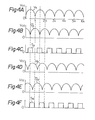
- the magnetoresistance pattern on the fixed member has first and second magnetoresistance elements which are electrically connected. In this case, when the first magnetoresistance element directly faces the strong magnetic field areas, the second magnetoresistance element directly faces to the weak magnetic field areas. As a result, the output voltage obtained at the connection between the first and second magnetoresistance elements reaches a maximum peak.
- the reference position of the rotating member can be determined by detecting such a maximum peak.
- an object of the present invention to provide a pulse coder in which no error of detection of the reference position of the rotating member is generated.
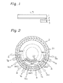
- reference numeral 1 designates a rotating member on which a magnetic layer 2 is coated. Predetermined magnetic patterns, which will be explained later, are formed on the magnetic layer 2.
- Reference numeral 3 designates a fixed member on which predetermined magnetoresistance patterns 4, which will also be explained later, are formed.
- the magnetic pattern 21 for generating an A-phase signal and a B-phase signal is formed on the entire circumference of the rotating member 1, while the magnetic pattern 22 for generating a Z-phase signal is formed on only part of a circumference of the rotating member 1.
- the magnetic pattern 22 will be later explained with reference to Figs. 5A and 5B.
- the resistance value of the magnetoresistance element MR5 is at a minimum, while the resistance value of the magnetoresistance element MR6 is at a maximum. In this case, therefore, the voltage V z at the connection between the magnetoresistance elements MR5 and MR6 reaches a maximum peak.
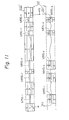
- the first magnetic pattern 221' and the second magnetic pattern 222' are formed in relation to each other. It should, however, be noted that the irregularity of the first magnetic pattern 221' can be independent of the irregularity of the second magnetic pattern 222'. In addition, the first magnetic pattern 221' and the second magnetic pattern 222' are formed on two different circumferences of the rotating member 1 (Fig. 1). The two patterns, however, can also be formed on the same circumference of the rotating member 1.
Landscapes
- Physics & Mathematics (AREA)
- General Physics & Mathematics (AREA)
- Engineering & Computer Science (AREA)
- Theoretical Computer Science (AREA)
- Transmission And Conversion Of Sensor Element Output (AREA)
Applications Claiming Priority (2)
| Application Number | Priority Date | Filing Date | Title |
|---|---|---|---|
| JP31687/82 | 1982-03-02 | ||
| JP57031687A JPS58148914A (ja) | 1982-03-02 | 1982-03-02 | パルスコ−ダ |
Publications (2)
| Publication Number | Publication Date |
|---|---|
| EP0087536A2 true EP0087536A2 (de) | 1983-09-07 |
| EP0087536A3 EP0087536A3 (de) | 1985-11-27 |
Family
ID=12337993
Family Applications (1)
| Application Number | Title | Priority Date | Filing Date |
|---|---|---|---|
| EP82306281A Withdrawn EP0087536A3 (de) | 1982-03-02 | 1982-11-25 | Impulscodierer |
Country Status (3)
| Country | Link |
|---|---|
| US (1) | US4551676A (de) |
| EP (1) | EP0087536A3 (de) |
| JP (1) | JPS58148914A (de) |
Cited By (5)
| Publication number | Priority date | Publication date | Assignee | Title |
|---|---|---|---|---|
| WO1985003346A1 (en) * | 1984-01-18 | 1985-08-01 | Stichting Centrum Voor Micro-Elektronica Twente | Position sensor |
| DE3719328A1 (de) * | 1986-06-10 | 1987-12-17 | Nippon Musical Instruments Mfg | Magnetoresistiver sensor fuer einen kodierer |
| WO1988006717A1 (en) * | 1987-02-24 | 1988-09-07 | Renishaw Plc | Scales for position determining apparatus |
| EP0685944A1 (de) * | 1994-06-01 | 1995-12-06 | Commissariat A L'energie Atomique | Kodierer zum Messen der Relativbewegung zwischen zwei Objekten |
| FR2736428A1 (fr) * | 1995-07-04 | 1997-01-10 | Schlumberger Ind Sa | Encodeur impulsionnel pour appareil de distribution de liquide |
Families Citing this family (31)
| Publication number | Priority date | Publication date | Assignee | Title |
|---|---|---|---|---|
| JPS595914A (ja) * | 1982-07-02 | 1984-01-12 | Hitachi Ltd | 磁気的に位置を検出する装置 |
| JPS6086412A (ja) * | 1983-10-19 | 1985-05-16 | Hitachi Ltd | 磁気検出装置 |
| JPH0762621B2 (ja) * | 1984-05-21 | 1995-07-05 | 株式会社井上ジャパックス研究所 | 磁気エンコーダ用零点検出装置 |
| US4746862A (en) * | 1985-05-14 | 1988-05-24 | Victor Company Of Japan Ltd. | Apparatus for detecting both rotational speed and reference rotational angle of a rotary member |
| US4785241A (en) * | 1985-08-08 | 1988-11-15 | Canon Denshi Kabushiki Kaisha | Encoder unit using magnetoresistance effect element |
| JPS62237314A (ja) * | 1986-04-08 | 1987-10-17 | Diesel Kiki Co Ltd | 回転角度検出装置 |
| JPS6474411A (en) * | 1987-09-16 | 1989-03-20 | Yamaha Corp | Position detector |
| US4803425A (en) * | 1987-10-05 | 1989-02-07 | Xerox Corporation | Multi-phase printed circuit board tachometer |
| JP2810695B2 (ja) * | 1989-04-28 | 1998-10-15 | 株式会社ソキア | インクリメンタル方式の磁気エンコーダの零点検出方式 |
| US5097209A (en) * | 1990-02-21 | 1992-03-17 | The Torrington Company | Magnetic encoder and sensor system for internal combustion engines |
| EP0555961B1 (de) * | 1992-02-13 | 1997-07-16 | Japan Servo Co. Ltd. | Absolutkodierer |
| JP2738199B2 (ja) * | 1992-03-02 | 1998-04-08 | 三菱電機株式会社 | 回転又は移動検出方法及びその装置 |
| JP3303333B2 (ja) * | 1992-06-09 | 2002-07-22 | 株式会社豊田自動織機 | 可変容量型圧縮機における容量検出装置 |
| DE4233331C2 (de) * | 1992-10-05 | 1995-06-01 | Inst Mikrostrukturtechnologie | Anordnung zur Bestimmung von Positionen |
| US5469054A (en) * | 1993-04-22 | 1995-11-21 | Honeywell Inc. | Position sensor with two magnetically sensitive devices and two target tracks which are sensed in combination with each other to provide a synthesized signal |
| DE4317512C2 (de) * | 1993-05-26 | 1995-03-30 | Univ Schiller Jena | Vorrichtung zur berührungslosen Nullpunkt-, Positions- und Drehwinkelmessung |
| JPH07194081A (ja) * | 1993-12-27 | 1995-07-28 | Canon Inc | モータ |
| EP0668486A3 (de) * | 1994-02-22 | 1997-07-30 | Heidenhain Gmbh Dr Johannes | Längen- oder Winkelmesseinrichtung. |
| DE4430467A1 (de) * | 1994-08-27 | 1995-10-19 | Danfoss As | Anordnung zum Messen der Lage eines beweglichen Gegenstands |
| US5764054A (en) * | 1996-06-19 | 1998-06-09 | Eastman Kodak Company | Contiguously matched magnetic sensor array and magnetic media for authentication of documents and products |
| US5976681A (en) * | 1997-06-30 | 1999-11-02 | Ford Global Technologies, Inc. | Giant magnetoresistors with high sensitivity and reduced hysteresis |
| US6097183A (en) * | 1998-04-14 | 2000-08-01 | Honeywell International Inc. | Position detection apparatus with correction for non-linear sensor regions |
| JP6003809B2 (ja) * | 2013-06-04 | 2016-10-05 | 株式会社デンソー | 回転検出装置 |
| US9797747B2 (en) | 2013-04-18 | 2017-10-24 | Denso Corporation | Rotation detector |
| DE112013006974B4 (de) * | 2013-04-23 | 2024-09-19 | Mitsubishi Electric Corporation | Magnetische-Position-Detektionsvorrichtung und Magnetische-Position-Detektionsverfahren |
| DE102015226666A1 (de) * | 2015-12-23 | 2017-06-29 | Frankl & Kirchner GmbH & Co KG Fabrik für Elektromotoren u. elektrische Apparate | Magnetisches Encodersystem für einen Servomotor einer Nähmaschine |
| EP3695041B1 (de) | 2017-10-13 | 2022-10-05 | Frankl & Kirchner GmbH & Co KG Fabrik für Elektromotoren u. elektrische Apparate | Nähmaschinenantrieb |
| US11326903B1 (en) | 2020-11-13 | 2022-05-10 | Allegro Microsystems, Llc | Rotary inductive sensor |
| US11460286B2 (en) * | 2020-11-13 | 2022-10-04 | Allegro Microsystems, Llc | Rotary inductive sensor |
| US12107710B2 (en) | 2020-11-19 | 2024-10-01 | Allegro Microsystems, Llc | Sensor signaling of absolute and incremental data |
| US12104900B2 (en) | 2022-09-29 | 2024-10-01 | Allegro Microsystems, Llc | Sensor with estimated real-time parameter data |
Family Cites Families (12)
| Publication number | Priority date | Publication date | Assignee | Title |
|---|---|---|---|---|
| DE1124998B (de) * | 1960-09-30 | 1962-03-08 | Siemens Ag | Signalgeber mit einem Hallgenerator-Abtastkopf |
| GB1472258A (en) * | 1973-09-15 | 1977-05-04 | Lucas Electrical Ltd | Pulse producing devices |
| JPS5725766B2 (de) * | 1973-12-12 | 1982-06-01 | ||
| DE2442919A1 (de) * | 1974-09-07 | 1976-03-25 | Labom Mess Und Regeltechnik Gm | Feldplatten-weggeber, insbesondere fuer die messwert-fernuebertragung |
| JPS6045804B2 (ja) * | 1978-02-28 | 1985-10-12 | 日本電気株式会社 | 角度検出器 |
| JPS54118259A (en) * | 1978-03-06 | 1979-09-13 | Nec Corp | Angle detector |
| JPS54156656A (en) * | 1978-05-31 | 1979-12-10 | Nippon Denso Co Ltd | Rotating position detector |
| JPS54163061A (en) * | 1978-06-15 | 1979-12-25 | Nippon Denso Co | Revolution positional detector |
| JPS5559314A (en) * | 1978-10-27 | 1980-05-02 | Sony Corp | Magnetic scale signal detector |
| DE2947412A1 (de) * | 1979-11-24 | 1981-06-04 | Robert Bosch Gmbh, 7000 Stuttgart | Drehzahl- oder drehwinkelgeber und zugehoerige auswerteschaltung |
| JPS6047988B2 (ja) * | 1979-12-19 | 1985-10-24 | 株式会社日立製作所 | 磁気ヘツド |
| DE2952106C2 (de) * | 1979-12-22 | 1982-11-04 | Dr. Johannes Heidenhain Gmbh, 8225 Traunreut | Lichtelektrische inkrementale Längen- oder Winkelmeßeinrichtung |
-
1982
- 1982-03-02 JP JP57031687A patent/JPS58148914A/ja active Pending
- 1982-11-25 EP EP82306281A patent/EP0087536A3/de not_active Withdrawn
- 1982-12-09 US US06/448,206 patent/US4551676A/en not_active Expired - Fee Related
Cited By (9)
| Publication number | Priority date | Publication date | Assignee | Title |
|---|---|---|---|---|
| WO1985003346A1 (en) * | 1984-01-18 | 1985-08-01 | Stichting Centrum Voor Micro-Elektronica Twente | Position sensor |
| DE3719328A1 (de) * | 1986-06-10 | 1987-12-17 | Nippon Musical Instruments Mfg | Magnetoresistiver sensor fuer einen kodierer |
| WO1988006717A1 (en) * | 1987-02-24 | 1988-09-07 | Renishaw Plc | Scales for position determining apparatus |
| US5004982A (en) * | 1987-02-24 | 1991-04-02 | Renishaw Plc | Scales for position determining apparatus having marks of different amplitudes thereon |
| EP0685944A1 (de) * | 1994-06-01 | 1995-12-06 | Commissariat A L'energie Atomique | Kodierer zum Messen der Relativbewegung zwischen zwei Objekten |
| FR2720881A1 (fr) * | 1994-06-01 | 1995-12-08 | Commissariat Energie Atomique | Codeur pour mesurer les mouvements relatifs entre deux objets. |
| US5719569A (en) * | 1994-06-01 | 1998-02-17 | Commissariat A L'energie Atomique | Coder for measuring relative movements between two objects |
| FR2736428A1 (fr) * | 1995-07-04 | 1997-01-10 | Schlumberger Ind Sa | Encodeur impulsionnel pour appareil de distribution de liquide |
| WO1997002473A1 (fr) * | 1995-07-04 | 1997-01-23 | Schlumberger Industries S.A. | Encodeur impulsionnel pour appareil de distribution de liquide |
Also Published As
| Publication number | Publication date |
|---|---|
| US4551676A (en) | 1985-11-05 |
| JPS58148914A (ja) | 1983-09-05 |
| EP0087536A3 (de) | 1985-11-27 |
Similar Documents
| Publication | Publication Date | Title |
|---|---|---|
| US4551676A (en) | Pulse coder using magnetoresistance elements having an improved z-phase signal pattern | |
| US5497082A (en) | Quadrature detector with a hall effect element and a magnetoresistive element | |
| US4866382A (en) | Magnetic rotary encoder system having a multi-element magnetoresistive sensor | |
| US4072893A (en) | Apparatus for determining the angular position of a rotating member using reference and position elements that generate opposite polarity bipolar signals | |
| US7022975B2 (en) | Angular position sensor | |
| EP0806673A2 (de) | Vorrichtung zur Ermittlung der Geschwindigkeit eines rotierenden Elements | |
| US5325056A (en) | Magnetic encoder with a plurality of magnetic signal-generating means having different magnetic pole pitches | |
| US6046584A (en) | Internal combustion engine rotating position detector using a differential signal from magnetic sensing portions | |
| US6496002B1 (en) | Rotation detector having a plurality of magnetism detection elements, a plurality of magnetic resistors which are able to switch the resistance from great to small and vice-versa | |
| US4678910A (en) | Reference position-detecting device for photoelectric encoder | |
| EP0372136B1 (de) | Magnetische Winkelkodieranordnung | |
| KR19990032844A (ko) | 로터리 엔코더 | |
| JPH0477246B2 (de) | ||
| JPS6363050B2 (de) | ||
| US4806860A (en) | Overlapped magnetoresistive displacement detecting transducers having closely spaced longitudinal centers | |
| JPH0450963B2 (de) | ||
| JP2810695B2 (ja) | インクリメンタル方式の磁気エンコーダの零点検出方式 | |
| JP3182880B2 (ja) | 回転検出装置 | |
| JP2630590B2 (ja) | 磁気エンコーダの零点検出装置 | |
| JPH0334700Y2 (de) | ||
| JPH052925B2 (de) | ||
| JP2527424B2 (ja) | 磁気ロ−タリ−エンコ−ダ | |
| JPH0469348B2 (de) | ||
| JPH0569446B2 (de) | ||
| JP2745627B2 (ja) | Acサーボモータ用磁気式ロータリエンコーダ |
Legal Events
| Date | Code | Title | Description |
|---|---|---|---|
| PUAI | Public reference made under article 153(3) epc to a published international application that has entered the european phase |
Free format text: ORIGINAL CODE: 0009012 |
|
| 17P | Request for examination filed |
Effective date: 19821130 |
|
| AK | Designated contracting states |
Designated state(s): DE FR GB |
|
| PUAL | Search report despatched |
Free format text: ORIGINAL CODE: 0009013 |
|
| AK | Designated contracting states |
Designated state(s): DE FR GB |
|
| 17Q | First examination report despatched |
Effective date: 19870805 |
|
| STAA | Information on the status of an ep patent application or granted ep patent |
Free format text: STATUS: THE APPLICATION IS DEEMED TO BE WITHDRAWN |
|
| 18D | Application deemed to be withdrawn |
Effective date: 19880329 |
|
| RIN1 | Information on inventor provided before grant (corrected) |
Inventor name: ISHIDA, HIROSHI Inventor name: AMEMIYA, YOICHI Inventor name: USHIYAMA, SHIGEYUKI Inventor name: TAKEKOSHI, YOSHITAKA |