EP0087768B1 - Neigungsmesser - Google Patents
Neigungsmesser Download PDFInfo
- Publication number
- EP0087768B1 EP0087768B1 EP83101824A EP83101824A EP0087768B1 EP 0087768 B1 EP0087768 B1 EP 0087768B1 EP 83101824 A EP83101824 A EP 83101824A EP 83101824 A EP83101824 A EP 83101824A EP 0087768 B1 EP0087768 B1 EP 0087768B1
- Authority
- EP
- European Patent Office
- Prior art keywords
- zero point
- gear
- inclinometer
- inclination
- indicator
- Prior art date
- Legal status (The legal status is an assumption and is not a legal conclusion. Google has not performed a legal analysis and makes no representation as to the accuracy of the status listed.)
- Expired
Links
- 230000007246 mechanism Effects 0.000 description 7
- 238000006073 displacement reaction Methods 0.000 description 6
- 230000005484 gravity Effects 0.000 description 2
- 230000005540 biological transmission Effects 0.000 description 1
- 238000004519 manufacturing process Methods 0.000 description 1
- 239000007787 solid Substances 0.000 description 1
Images


Classifications
-
- G—PHYSICS
- G01—MEASURING; TESTING
- G01C—MEASURING DISTANCES, LEVELS OR BEARINGS; SURVEYING; NAVIGATION; GYROSCOPIC INSTRUMENTS; PHOTOGRAMMETRY OR VIDEOGRAMMETRY
- G01C9/00—Measuring inclination, e.g. by clinometers, by levels
- G01C9/16—Measuring inclination, e.g. by clinometers, by levels by using more than one pendulum
-
- G—PHYSICS
- G01—MEASURING; TESTING
- G01C—MEASURING DISTANCES, LEVELS OR BEARINGS; SURVEYING; NAVIGATION; GYROSCOPIC INSTRUMENTS; PHOTOGRAMMETRY OR VIDEOGRAMMETRY
- G01C9/00—Measuring inclination, e.g. by clinometers, by levels
-
- G—PHYSICS
- G01—MEASURING; TESTING
- G01C—MEASURING DISTANCES, LEVELS OR BEARINGS; SURVEYING; NAVIGATION; GYROSCOPIC INSTRUMENTS; PHOTOGRAMMETRY OR VIDEOGRAMMETRY
- G01C9/00—Measuring inclination, e.g. by clinometers, by levels
- G01C9/02—Details
Definitions
- This invention relates to an inclinometer adapted to be mounted on a vehicle.
- inclinometers are mounted on motor cars and other vehicles for quantitatively displaying the inclination of the road surface on which the vehicles are running.
- a gear transmission weight type comprising a drive member including a weight which rotates in response to inclination of a vehicle, a driven member responsive to the rotational torque of the drive member, and an indicator secured to the shaft of the driven member for displaying the inclination angle.
- the zero point can not always be displayed due to the error of the zero point display caused by manufacturing error, error in the horizontal criterion at the time of mounting the inclinometer on the vehicle, and inclination of the vehicle body due to uneven loading.
- a disc shaped inclination indicator 2 is secured to one end of a drive shaft 1 driven by a drive mechanism, not shown, and a scale board 3 is coaxially disposed adjacent the inclination indicator 2.
- the scale board 3 is rotatably supported by a guide ring 4.
- the scale board 3 is rotated to make its zero point 0 (thick solid graduation) coincide with the display line P of the indicator 2.
- the scale board 3 is rotated in a direction of arrow a to establish a zero point display as shown in Fig. 1C.
- the dial ring 4 is marked with digits 0, 20, 40 ... indicating inclination angles corresponding to. respective scale lines of the scale board 3.
- a pointer 5 is provided to oppose the periphery of an indicator 2a secured to one end of a driven shaft, as shown in Fig. 2A, and the pointer is rotated in the direction of arrows to set it at the zero point of the indicator 2a.
- the pointer 5 is rotated in a direction of arrow b to establish a zero point display as shown in Fig. 2B.
- Another object of this invention is to provide an inclinometer in which the zero point at which the torque of a hair spring and the torque created by a weight will balance with each other, can readily be adjusted.
- an inclinometer as defined in claim 1.
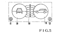
- a preferred embodiment of this invention shown in Figs. 3; 4 and 5 comprises a frame 10 having a configuration as shown.
- a side plate 10a of the frame 10 is formed with an opening 11 for rotatably supporting a drive shaft 12 for fore and aft inclination indication, and a drive gear 13 is secured to the drive shaft 12 in parallel with the side plate 10a.
- a weight 14 acting as a drive source is mounted on the drive gear 13 perpendicular to its periphery (for the sake of depiction, the weight 14 is shown displaced 90°) so that the drive gear 13 is rotated corresponding to the displacement of the weight 14.
- a driven gear 15 orthogonal to the drive gear 13 meshes therewith.
- the driven gear 15 is secured to one end of a horizontal driven shaft 16 journaled at openings of fore and aft plates 10b and 10c of the frame 10.
- the inner end of a zero point adjusting spiral hair spring 17 is secured to one end of the driven shaft 16, and the outer end of the spring 17 is secured to a spring drive gear 18 coaxial with the driven shaft 16.
- a disc shaped fore and aft inclination indicator 19 is secured to the front end of the driven shaft 16. Accordingly, when the drive gear 13 rotates in response to the displacement of the weight 14, torque is transmitted to the driven gear 15 to rotate the driven shaft 16 so that the inclination indicator 19 displays an inclination angle proportional to the torque caused by the displacement of the weight 14 with respect to a scale board 60 shown in Fig. 5.
- the hair spring drive gear 18 is associated with a zero point adjusting mechanism 20 for balancing the torque caused by the weight 14 and the hair spring 17.
- This mechanism 20 comprises a zero point adjusting knob 22 on the righthand side of a panel 21, a correction gear 23 rotatably supported by a shaft 28 of the knob 22, and a reversing gear 24 meshing with the correction gear 23, and the hair spring drive gear 18 meshes with the reversing gear 24.
- the gear 18 will be rotated in the same direction through gears 23 and 24to apply a torque to the spring 17, thereby contracting the zero point adjusting spring 17.
- gears 23 and 24 are respectively secured to shafts 28 and 29 journaled by bearings 26 and 27 supported by a frame 25.
- a bearing 31 is secured to a frame 30 secured to a side plate 10d of the frame 10 to extend in the horizontal direction, and a left and right inclination drive shaft 32 is supported between a front plate 1 Obi of the frame 10 and the bearing 31 to extend in the horizontal direction.
- the drive shaft 32 carries a drive gear 33, and a weight 34 acting as a drive source is mounted on the gear 34 (for the sake of depiction, shown at a position displaced by 90°).
- the drive gear 33 meshes with a driven gear 36 on a driven shaft 35 rotatably supported between the front plate 10bl of the frame 10 and the frame 30.
- a zero point adjusting spiral hair spring 37 is secured to the front end of the driven shaft 35, while the other end is secured to a spring drive gear 38 concentric with the driven shaft 35.
- a disc shaped left and right inclination indicator 39 is secured to the front end of the drive shaft 35. Consequently, the indicator 39 displays, with respect to a scale board 60, an inclination angle proportional to torque caused by the displacement of the weight 34 which occurs when the torque of the drive gear 33 is transmitted to the driven gear 36.
- Azero point adjusting mechanism 40 is provided for the hair spring drive gear 38 for balancing the torque caused by the weight 34 and the zero point adjusting hair spring 37.
- the zero point adjusting mechanism 40 comprises a zero point adjusting knob 41 on the lefthand side of the panel 21, a correction gear 42 rotatably supported by the knob 41, and a reversing gear 43 meshing with the correction gear 42 and with the hair spring drive gear 38.
- the spring drive gear 38 When the zero adjusting knob 41 is rotated in the clockwise direction, the spring drive gear 38 will be rotated in the same direction through gears 42 and 43 to contract the zero point adjusting hair spring 37. Conversely, as the knob 41 is rotated in the counterclockwise direction, the spring 37 is expanded.
- the gears 42 and 43 are supported by shafts 47 and 48 respectively journaled by bearings 45 and 46 provided for a frame 44.
- a clamping spring 50 is secured to the front end 49 of the frame 10 with screws, not shown, for preventing accidental removal of the hair spring drive gears 18 and 38.
- the scale board 60 graduated with inclination angles is provided on the panel 21 to confront the periphery of the fore and aft inclination indicator 19, and left and right inclination indicator 39, respectively.
- the inclinometer described above operates as follows. It is now assumed that the panel 21 of the inclinometer is mounted vertically on the dash board of a vehicle. When the vehicle inclines in the fore and aft direction, the weight 14 rotates the drive shaft 12 because the weight has a tendency to maintain the horizontal criterion owing to gravity exerting thereon. Then the drive shaft 12 is rotated by a torque proportional to the amount of relative displacement of the weight to drive the drive gear 13. Consequently, the driven gear 15 rotates againstthe force of the zero point adjusting hair spring to rotate the fore and aft inclination indicator 19. Thus, the indicator 19 displays a fore and aft inclination angle of the vehicle proportional to the torque applied by the weight 14.
- the weight 34 rotates the drive shaft 32. Then the drive shaft 32 is rotated by a torque proportional to the amount of relative displacement of the weight 34 to rotate the drive gear 33, whereby the driven gear 36 is rotated against the force of the zero point adjusting hair spring 37 to rotate the left and right inclination indicator 39.
- the indicator 39 displays a left and right inclination angle of the vehicle proportional to the torque exerted by the weight 34.
- the inclinometer When mounting an inclinometer on a vehicle, the inclinometer is not always mounted at a correct horizontal position so that the zero point display of the fore and aft inclination indicator 19 - would not display a correct zero point.
- the zero adjust knob 22 is rotated in the clockwise direction.
- the correction gear 23 rotates in the direction of arrow a shown in Fig. 3 to rotate the reversing gear 24 in the direction of arrow b, thus rotating the spiral hair drive gear 18 in the direction of c.
- a torque is applied to the outer end of the hair spring 17 in a direction of arrow d to contract the spring.
- the driven shaft 16 rotates by an angle ⁇ corresponding to the torque to change a point at which the torque applied by the weight and the torque of the spring balance with each other.
- the zero adjust knob 22 is rotated in the counterclockwise direction to adjust the zero point.
- the zero adjust knob 41 is rotated.
- a zero point adjusting spiral hair spring is secured to a drive shaft, or driven shaft of the inclinometer while the outer end of the spring is adjusted by a knob for changing a point at which torque caused by a weight and a torque applied by the spring balance with each other. Accordingly, the zero point can be adjusted readily and after adjustment of the zero point display line, and the zero point scale line can be aligned horizontally, thereby improving appearance of display of the zero point. Furthermore, since spring force of the hair spring is constantly applied to the gears, backlash thereof can advantageously be eliminated to cause the inclinometer to correctly follow inclinations, giving rise to correct display of inclination angles.
Landscapes
- Physics & Mathematics (AREA)
- Engineering & Computer Science (AREA)
- General Physics & Mathematics (AREA)
- Radar, Positioning & Navigation (AREA)
- Remote Sensing (AREA)
- A Measuring Device Byusing Mechanical Method (AREA)
Claims (3)
Applications Claiming Priority (2)
| Application Number | Priority Date | Filing Date | Title |
|---|---|---|---|
| JP27016/82U | 1982-02-26 | ||
| JP1982027016U JPS58130209U (ja) | 1982-02-26 | 1982-02-26 | 傾斜計 |
Publications (3)
| Publication Number | Publication Date |
|---|---|
| EP0087768A2 EP0087768A2 (de) | 1983-09-07 |
| EP0087768A3 EP0087768A3 (en) | 1984-02-22 |
| EP0087768B1 true EP0087768B1 (de) | 1986-11-20 |
Family
ID=12209291
Family Applications (1)
| Application Number | Title | Priority Date | Filing Date |
|---|---|---|---|
| EP83101824A Expired EP0087768B1 (de) | 1982-02-26 | 1983-02-24 | Neigungsmesser |
Country Status (4)
| Country | Link |
|---|---|
| US (1) | US4426788A (de) |
| EP (1) | EP0087768B1 (de) |
| JP (1) | JPS58130209U (de) |
| DE (1) | DE3367808D1 (de) |
Families Citing this family (6)
| Publication number | Priority date | Publication date | Assignee | Title |
|---|---|---|---|---|
| FR2598220B1 (fr) * | 1986-05-02 | 1990-03-30 | Auxitrol Mat Auxil Signalis Co | Dispositif pour la mesure du niveau d'un liquide, notamment d'un liquide inflammable |
| US4926690A (en) * | 1988-03-07 | 1990-05-22 | Oberg Paul E | Pendulous accelerometer and/or inclinometer |
| US5467533A (en) * | 1994-01-28 | 1995-11-21 | Avionic Displays Corporation | Night vision inclinometer |
| FR2776376B1 (fr) * | 1998-03-17 | 2000-06-23 | Daniel Legrand | Appareil pour mesurer de maniere precise et directe l'inclinaison d'un plan par rapport a un autre plan |
| US6232150B1 (en) | 1998-12-03 | 2001-05-15 | The Regents Of The University Of Michigan | Process for making microstructures and microstructures made thereby |
| US7017701B2 (en) * | 2002-11-20 | 2006-03-28 | Dura Global Technologies, Inc. | Inclination-measuring device |
Family Cites Families (7)
| Publication number | Priority date | Publication date | Assignee | Title |
|---|---|---|---|---|
| GB321736A (en) | 1928-11-30 | 1929-11-21 | Kelvyn King | Improvements in trim indicators for ships |
| DE546532C (de) * | 1929-11-20 | 1932-03-15 | Maurice Cuendet | Pendelneigungsmesser |
| DE578081C (de) * | 1930-02-13 | 1933-06-09 | Kreidler Dipl Ing Alfred | Schraeglageanzeiger und Neigungsmesser |
| US2355517A (en) | 1941-03-03 | 1944-08-08 | Weese Herbert F De | Airplane flight indicator |
| US2651848A (en) | 1948-08-02 | 1953-09-15 | Jack W Sims | Level |
| DE835353C (de) * | 1950-08-18 | 1952-03-31 | Georg Waidmann | Steigungsanzeiger |
| US3378932A (en) | 1966-11-04 | 1968-04-23 | Frank E. Neill | Grade indicator |
-
1982
- 1982-02-26 JP JP1982027016U patent/JPS58130209U/ja active Pending
-
1983
- 1983-02-24 US US06/469,380 patent/US4426788A/en not_active Expired - Fee Related
- 1983-02-24 EP EP83101824A patent/EP0087768B1/de not_active Expired
- 1983-02-24 DE DE8383101824T patent/DE3367808D1/de not_active Expired
Also Published As
| Publication number | Publication date |
|---|---|
| EP0087768A2 (de) | 1983-09-07 |
| US4426788A (en) | 1984-01-24 |
| JPS58130209U (ja) | 1983-09-02 |
| DE3367808D1 (en) | 1987-01-08 |
| EP0087768A3 (en) | 1984-02-22 |
Similar Documents
| Publication | Publication Date | Title |
|---|---|---|
| US4426788A (en) | Inclinometers | |
| US4173146A (en) | Apparatus for balancing unbalanced bodies | |
| US4429470A (en) | Inclinometer | |
| GB2034905A (en) | Device for measuring the tightening angle of a wrench | |
| US2934035A (en) | Steering indicator | |
| US2959057A (en) | Accelerometer | |
| JPH04240502A (ja) | 差動歯車噛合い間隙測定装置 | |
| US3516055A (en) | Internally gimbaled attitude indicator | |
| US3220276A (en) | Position analog unit for automatic controls | |
| JPH0233133Y2 (de) | ||
| US4351187A (en) | Single cue drive for flight director indicator | |
| US3926142A (en) | Meter | |
| JPS61182503A (ja) | 機械装置の回転部分に取付けられ、該回転部分の回転量を指示する装置 | |
| JP3164694B2 (ja) | 釣合い試験機 | |
| CN112918560A (zh) | 一种汽车转向回正指示器 | |
| US2411521A (en) | Dial head unit for weighing and recording scales | |
| US3166935A (en) | Continuous reading torque meter | |
| US2910037A (en) | Mechanical tachometer | |
| JPS6318300Y2 (de) | ||
| JP2617736B2 (ja) | 電動パワーステアリング装置 | |
| US2044825A (en) | Speed indicator | |
| CN2402993Y (zh) | 双盘面指针型百分表 | |
| JPS589319Y2 (ja) | 数字車の早送り装置 | |
| US3608306A (en) | Plane indicator setting arrangement | |
| JPH076716U (ja) | 傾斜計 |
Legal Events
| Date | Code | Title | Description |
|---|---|---|---|
| PUAI | Public reference made under article 153(3) epc to a published international application that has entered the european phase |
Free format text: ORIGINAL CODE: 0009012 |
|
| AK | Designated contracting states |
Designated state(s): DE FR GB |
|
| PUAL | Search report despatched |
Free format text: ORIGINAL CODE: 0009013 |
|
| AK | Designated contracting states |
Designated state(s): DE FR GB |
|
| 17P | Request for examination filed |
Effective date: 19840622 |
|
| RIN1 | Information on inventor provided before grant (corrected) |
Inventor name: KOMIYA, HIROKAZU Inventor name: IIYAMA, HIROSHI Inventor name: ARAI, HIROSHI Inventor name: HIROSE, HISASHI |
|
| GRAA | (expected) grant |
Free format text: ORIGINAL CODE: 0009210 |
|
| AK | Designated contracting states |
Kind code of ref document: B1 Designated state(s): DE FR GB |
|
| REF | Corresponds to: |
Ref document number: 3367808 Country of ref document: DE Date of ref document: 19870108 |
|
| ET | Fr: translation filed | ||
| PLBE | No opposition filed within time limit |
Free format text: ORIGINAL CODE: 0009261 |
|
| STAA | Information on the status of an ep patent application or granted ep patent |
Free format text: STATUS: NO OPPOSITION FILED WITHIN TIME LIMIT |
|
| 26N | No opposition filed | ||
| PGFP | Annual fee paid to national office [announced via postgrant information from national office to epo] |
Ref country code: GB Payment date: 19910115 Year of fee payment: 9 |
|
| PGFP | Annual fee paid to national office [announced via postgrant information from national office to epo] |
Ref country code: FR Payment date: 19910117 Year of fee payment: 9 |
|
| PGFP | Annual fee paid to national office [announced via postgrant information from national office to epo] |
Ref country code: DE Payment date: 19910412 Year of fee payment: 9 |
|
| PG25 | Lapsed in a contracting state [announced via postgrant information from national office to epo] |
Ref country code: GB Effective date: 19920224 |
|
| GBPC | Gb: european patent ceased through non-payment of renewal fee | ||
| PG25 | Lapsed in a contracting state [announced via postgrant information from national office to epo] |
Ref country code: FR Effective date: 19921030 |
|
| PG25 | Lapsed in a contracting state [announced via postgrant information from national office to epo] |
Ref country code: DE Effective date: 19921103 |
|
| REG | Reference to a national code |
Ref country code: FR Ref legal event code: ST |