EP0088663A1 - Fokussierungssolenoid, Anwendung und Herstellungsverfahren desselben - Google Patents
Fokussierungssolenoid, Anwendung und Herstellungsverfahren desselben Download PDFInfo
- Publication number
- EP0088663A1 EP0088663A1 EP83400363A EP83400363A EP0088663A1 EP 0088663 A1 EP0088663 A1 EP 0088663A1 EP 83400363 A EP83400363 A EP 83400363A EP 83400363 A EP83400363 A EP 83400363A EP 0088663 A1 EP0088663 A1 EP 0088663A1
- Authority
- EP
- European Patent Office
- Prior art keywords
- sleeve
- layers
- wire
- turns
- layer
- Prior art date
- Legal status (The legal status is an assumption and is not a legal conclusion. Google has not performed a legal analysis and makes no representation as to the accuracy of the status listed.)
- Granted
Links
Images


Classifications
-
- H—ELECTRICITY
- H01—ELECTRIC ELEMENTS
- H01J—ELECTRIC DISCHARGE TUBES OR DISCHARGE LAMPS
- H01J23/00—Details of transit-time tubes of the types covered by group H01J25/00
- H01J23/02—Electrodes; Magnetic control means; Screens
- H01J23/08—Focusing arrangements, e.g. for concentrating stream of electrons, for preventing spreading of stream
- H01J23/087—Magnetic focusing arrangements
-
- H—ELECTRICITY
- H01—ELECTRIC ELEMENTS
- H01J—ELECTRIC DISCHARGE TUBES OR DISCHARGE LAMPS
- H01J29/00—Details of cathode-ray tubes or of electron-beam tubes of the types covered by group H01J31/00
- H01J29/46—Arrangements of electrodes and associated parts for generating or controlling the ray or beam, e.g. electron-optical arrangement
- H01J29/58—Arrangements for focusing or reflecting ray or beam
- H01J29/64—Magnetic lenses
- H01J29/66—Magnetic lenses using electromagnetic means only
-
- H—ELECTRICITY
- H01—ELECTRIC ELEMENTS
- H01J—ELECTRIC DISCHARGE TUBES OR DISCHARGE LAMPS
- H01J3/00—Details of electron-optical or ion-optical arrangements common to two or more basic types of discharge tubes or lamps
- H01J3/14—Arrangements for focusing or reflecting ray or beam
- H01J3/20—Magnetic lenses
- H01J3/22—Magnetic lenses using electromagnetic means only
-
- H—ELECTRICITY
- H01—ELECTRIC ELEMENTS
- H01J—ELECTRIC DISCHARGE TUBES OR DISCHARGE LAMPS
- H01J37/00—Discharge tubes with provision for introducing objects or material to be exposed to the discharge, e.g. for the purpose of examination or processing thereof
- H01J37/02—Details
- H01J37/04—Arrangements of electrodes and associated parts for generating or controlling the discharge, e.g. electron-optical arrangement or ion-optical arrangement
- H01J37/10—Lenses
- H01J37/14—Lenses magnetic
- H01J37/141—Electromagnetic lenses
-
- H—ELECTRICITY
- H01—ELECTRIC ELEMENTS
- H01F—MAGNETS; INDUCTANCES; TRANSFORMERS; SELECTION OF MATERIALS FOR THEIR MAGNETIC PROPERTIES
- H01F5/00—Coils
- H01F5/02—Coils wound on non-magnetic supports, e.g. formers
- H01F2005/025—Coils wound on non-magnetic supports, e.g. formers wound on coaxial arrangement of two or more formers
-
- Y—GENERAL TAGGING OF NEW TECHNOLOGICAL DEVELOPMENTS; GENERAL TAGGING OF CROSS-SECTIONAL TECHNOLOGIES SPANNING OVER SEVERAL SECTIONS OF THE IPC; TECHNICAL SUBJECTS COVERED BY FORMER USPC CROSS-REFERENCE ART COLLECTIONS [XRACs] AND DIGESTS
- Y10—TECHNICAL SUBJECTS COVERED BY FORMER USPC
- Y10T—TECHNICAL SUBJECTS COVERED BY FORMER US CLASSIFICATION
- Y10T29/00—Metal working
- Y10T29/49—Method of mechanical manufacture
- Y10T29/49002—Electrical device making
- Y10T29/4902—Electromagnet, transformer or inductor
- Y10T29/49071—Electromagnet, transformer or inductor by winding or coiling
Definitions
- the present invention relates to a focusing solenoid. It also relates to the application and a method of manufacturing this solenoid.
- the present invention relates to the field of focusing of an electron beam in an electron tube.
- an electronic tube it is known to provide a focusing device having the function of opposing the natural divergence of the electrons of the beam. This device often creates a magnetic field directed along the axis of the tube and causing the rotation around this axis of the divergent electrons.
- the beam concentration requirements are particularly stringent. This is the case, for example, of electronic tubes intended for taking pictures, electronic microscopes and microwave electronic tubes.
- a solenoid arranged around the tube, and constituted by an insulated metal wire, of enamelled copper for example, which is wound in the form of a helix around '' an insulating sleeve, in epoxy glass for example.
- the turns of the propeller are contiguous and the solenoid has several layers of superimposed wire, having the same direction of winding around the sleeve.
- the wire is wound onto the sleeve using a lathe with a wire guide and the arrangement of the turns is controlled by hand. After having wound a layer, it is wound over the next layer, without cutting the wire, but by reversing the inclination of the turns on the axis.
- the direction of winding of the wire around the sleeve is always the same and the current always flows in the same direction. which makes it possible, as a first approximation, to obtain a uniform magnetic field parallel to the axis.
- Two flanges attached to the ends of the sleeve hold the layers of wire in place.
- this solenoid causes a parasitic deflection of the image which results in a "framing". It also causes an orthogonality error.
- the rapid return of the beam controlled by the deflection coils constitutes a parasite which is transmitted to the target by the focusing solenoid, which disturbs the video signal.
- the modulation rate varies from one solenoid to another, and we also observe a lack of homogeneity in tube resolution.
- the present invention relates to a new focusing solenoid which eliminates the faults due to known focusing solenoids by ensuring a regular distribution of the turns.
- This new solenoid also has the advantage of being easier to manufacture.
- the present invention relates to a focusing solenoid whose sleeve, around which the wire is wound is cylindrical and carries a helical engraving in which are housed the turns of the first layer of wire.
- Figure 1 illustrates, schematically, the constitution of a focusing solenoid according to the prior art.
- This solenoid is obtained by winding an insulated metal wire 1 on an insulating cylindrical sleeve which is not shown in the figure.
- the wire is wound in the form of a helix around the sleeve and the turns of the helix are joined as shown in the figure.
- the turns of the helix are joined as shown in the figure.
- FIG. 1 it can be seen that for the layer C 1 , the turns of the propeller are inclined to the right on the axis 00 'of the sleeve, while for the layer C 2 , the turns of the propeller are inclined a left. So the current always flows in the same direction throughout the solenoid.
- the direction of current flow in the layer of wire C 1 has been indicated by an arrow. The current flows in this layer from bottom to top in the figure, that is to say in the anticlockwise direction if the solenoid is seen from the left side.
- the direction of flow of the current in the layer of wire C is also indicated by an arrow and it can be seen that the current also flows in this layer in an anticlockwise direction if the solenoid is seen from the left side.
- the third is wound by tilting the turns to the right and so on for the other layers, each time the inclination of the turns on the axis is reversed.
- FIG. 2 schematically illustrates the constitution of a focusing solenoid according to the invention.
- this sleeve carries a helical engraving in which are housed the turns of the first layer C 1 of wire 1 which is represented on the left part of FIG. 2.
- the pitch of the propeller engraved on the sleeve must be very slightly greater than the diameter of the wire so that the turns of the wire are substantially joined.
- the depth of the engraving made on the sleeve is about half the diameter of the wire.
- the depth of the engraving is 1 / 10th.
- the first layer of wire C 1 therefore exceeds the engraving by about half of the wire diameter.
- This etching of the sleeve is however sufficient for the turns of the first layer C 1 to be well held in place.
- the solenoid it is always done using a lathe and a wire guide but we see that it is no longer necessary to guide the wire by hand only for the first turns, because the wire comes then place itself in the engraving of the sleeve.
- the distribution of the turns of the first layer on the sleeve is almost perfect and the turns are therefore substantially perpendicular to the axis of the sleeve.
- the distribution of the turns of the first layer on the sleeve is generally much less regular and, in any case, a regular distribution of the turns is much more difficult to achieve.
- FIG. 3 shows that in the solenoid according to the invention, for each layer of wire, the inclination of the turns of the propeller relative to the sleeve is the same.
- the first layer C 1 of wire which protrudes from the etching of the sleeve serves as a guide for the second layer C 2 , the turns of which have the same inclination as those of the first.
- each layer of wire is used to position the next layer of wire.
- all the layers of wire have well distributed turns and substantially perpendicular to the axis of the sleeve and, to produce the solenoid, at each layer, the wire should only be guided by hand for the first turns.
- Figures 4a and b are sections schematically showing how the different layers of wire, C n + 1 , C n and C n-1.
- Figure 5 is a longitudinal sectional view along the axis 00 'schematically showing an embodiment of a solenoid according to the invention which advantageously solves the problem of connections between the layers.
- the solenoid according to the invention comprises a first sleeve 2 such as that of FIG. 2.
- This sleeve 2 carries half of the layers of the solenoid.
- C d denotes the set of layers carried by this sleeve 2.
- the first layer of wire is produced by housing the turns of the propeller in the helical etching of the sleeve 2.
- the wire is cut when you reach the end of the first layer.
- a second layer is wound over the first layer using the first layer as a guide, as shown in Figure 3.
- the wire is cut at the end of the second layer.
- Half of the layers are thus wound around the sleeve, cutting the wire at the end of each layer, and so that the inclination of the turns of the propeller relative to the sleeve is substantially the even for all these layers.
- a second sleeve 3 is introduced, similar to the first and having the same helical engraving but produced in the opposite direction.
- connections are made between the ends of a layer made around a sleeve and the ends, located on the same side of the sleeves, of two other layers made around the other sleeve.
- FIG. 6 shows the connections that had to be made to properly connect a layer C n inclined to the left, belonging to the layers C wound around the second sleeve, to two layers C n-1 and C n + 1 inclined on the right, belonging to the layers C d wound around the first sleeve.
- connection c 1 the end of the layer C n-1 located to the right of the sleeves in the figure at the end of the layer C n located to the right of the sleeves, and we connect by the connection c 2 J ' end of layer C n situated to the left of the sleeves at the end of layer C n + 1 situated to the left of the sleeves.
- connections such as c and c 2 between the ends located on the same side of the sleeves of two neighboring layers are made by twisting together two short pieces of wire which are then soldered, by immersing them in a tin of molten tin for example.
- the connections thus made cannot produce annoying parasites.
- each sleeve carries only a single layer housed in the helical engraving of the sleeve.
- the first half C d of the layers is wrapped around the first sleeve 2, cutting the wire at each layer, and winding all the layers while retaining the same inclination. This first step is shown on the left side of Figure 7.
- a second sleeve 3 is then used, the external diameter of which is equal to the external diameter of the first sleeve covered with its layers of wire.
- This second sleeve is etched in the opposite direction to the first and we wrap around this second sleeve J'autre half des couches C f , as we did around the first. This second step is shown on the right side of Figure 7.
- the wire which is used to make at least this other half of layers C has the property of becoming adherent under the action of heat.
- these layers C are agglomerated together using a jet of hot air or by passing a current high intensity in the wire.
- the second sleeve is then chased.
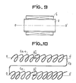
- a removable sleeve in three parts such as that shown in Figure 8. It suffices to remove the central part 4 and the side parts 5 and 6 are released.
- the second half of layers C is then adjusted to the first half of layers C d . IJ then suffices to make the connections between the different layers.
- This process can of course be used when more than two sleeves are used.
- connections such as connection c 3 in FIG. 10, connect the end of a layer such as C n-1 to the end of the next layer C n located on the other side of the sleeve 2.
- connection c 3 connects the right end of layer C n-1 to the left end of layer C.
- epoxy glass sleeves are generally used. Due to their manufacture, these sleeves have a fairly irregular external surface and often off-center with respect to the axis of the tube. On the other hand, their internal surface is perfectly centered with respect to this axis. According to the invention, sleeves with a helical engraving on their external surface are used. It suffices to perform this etching based on the inner wall of the sleeve to eliminate the drawbacks due to defects in the external surface of the sleeves.
- the solenoids according to the invention have the advantage of being easier to manufacture than known solenoids, in particular because the wire no longer has to be guided by hand except for the first turns of each layer after which it place alone.
- the focusing solenoids according to the invention have reproducible characteristics. This is an important advantage because these solenoids are often used in color shooting tubes where I need three focusing solenoids with similar characteristics.
- the invention can also be used for the manufacture of transformers or motors.
Landscapes
- Physics & Mathematics (AREA)
- Electromagnetism (AREA)
- Chemical & Material Sciences (AREA)
- Analytical Chemistry (AREA)
- Electromagnets (AREA)
- Coil Winding Methods And Apparatuses (AREA)
- Coils Or Transformers For Communication (AREA)
Applications Claiming Priority (2)
| Application Number | Priority Date | Filing Date | Title |
|---|---|---|---|
| FR8203731A FR2522876A1 (fr) | 1982-03-05 | 1982-03-05 | Solenoide de focalisation, application et procede de fabrication de ce solenoide |
| FR8203731 | 1982-03-05 |
Publications (2)
| Publication Number | Publication Date |
|---|---|
| EP0088663A1 true EP0088663A1 (de) | 1983-09-14 |
| EP0088663B1 EP0088663B1 (de) | 1986-12-30 |
Family
ID=9271661
Family Applications (1)
| Application Number | Title | Priority Date | Filing Date |
|---|---|---|---|
| EP83400363A Expired EP0088663B1 (de) | 1982-03-05 | 1983-02-22 | Fokussierungssolenoid, Anwendung und Herstellungsverfahren desselben |
Country Status (5)
| Country | Link |
|---|---|
| US (1) | US4511870A (de) |
| EP (1) | EP0088663B1 (de) |
| JP (1) | JPS58162007A (de) |
| DE (1) | DE3368808D1 (de) |
| FR (1) | FR2522876A1 (de) |
Cited By (1)
| Publication number | Priority date | Publication date | Assignee | Title |
|---|---|---|---|---|
| WO2015117587A1 (de) * | 2014-02-05 | 2015-08-13 | Schlaeger Kunststofftechnik Gmbh | Stellvorrichtung zur durchleitung eines fluids |
Families Citing this family (5)
| Publication number | Priority date | Publication date | Assignee | Title |
|---|---|---|---|---|
| FR2609206B1 (fr) * | 1986-12-30 | 1992-02-14 | Thomson Cgr | Dispositif correcteur par elements magnetiques d'inhomogeneites du champ magnetique dans un aimant |
| JPH10233331A (ja) * | 1997-02-19 | 1998-09-02 | Toyo Denso Co Ltd | 点火コイルのバンク巻方法 |
| JP3167679B2 (ja) * | 1998-06-09 | 2001-05-21 | ファナック株式会社 | ステータの巻回方法 |
| JP3182125B2 (ja) * | 1998-06-09 | 2001-07-03 | ファナック株式会社 | 空気軸受けモータ |
| US20090021652A1 (en) * | 2007-07-17 | 2009-01-22 | Motorola, Inc. | Microprojector with a detachable interaction device |
Citations (3)
| Publication number | Priority date | Publication date | Assignee | Title |
|---|---|---|---|---|
| US2763805A (en) * | 1954-06-29 | 1956-09-18 | Rca Corp | Electromagnetic focus coil for cathode ray tube |
| FR2181464A1 (de) * | 1972-04-25 | 1973-12-07 | Barthalon Maurice | |
| EP0019328A1 (de) * | 1979-05-14 | 1980-11-26 | Koninklijke Philips Electronics N.V. | Elektromagnetische Vorrichtung zur Fokussierung und Ablenkung von Elektronenstrahlen |
Family Cites Families (2)
| Publication number | Priority date | Publication date | Assignee | Title |
|---|---|---|---|---|
| US2706366A (en) * | 1950-11-25 | 1955-04-19 | Bell Telephone Labor Inc | Method of constructing a helix assembly |
| US2982888A (en) * | 1957-05-23 | 1961-05-02 | Rea Magnet Wire Company Inc | Sleeve type encapsulated electrical component |
-
1982
- 1982-03-05 FR FR8203731A patent/FR2522876A1/fr active Granted
-
1983
- 1983-02-22 DE DE8383400363T patent/DE3368808D1/de not_active Expired
- 1983-02-22 EP EP83400363A patent/EP0088663B1/de not_active Expired
- 1983-02-28 US US06/470,526 patent/US4511870A/en not_active Expired - Fee Related
- 1983-03-04 JP JP58035691A patent/JPS58162007A/ja active Pending
Patent Citations (3)
| Publication number | Priority date | Publication date | Assignee | Title |
|---|---|---|---|---|
| US2763805A (en) * | 1954-06-29 | 1956-09-18 | Rca Corp | Electromagnetic focus coil for cathode ray tube |
| FR2181464A1 (de) * | 1972-04-25 | 1973-12-07 | Barthalon Maurice | |
| EP0019328A1 (de) * | 1979-05-14 | 1980-11-26 | Koninklijke Philips Electronics N.V. | Elektromagnetische Vorrichtung zur Fokussierung und Ablenkung von Elektronenstrahlen |
Non-Patent Citations (1)
| Title |
|---|
| PATENTS ABSTRACTS OF JAPAN, vol. 2, no 154(E78), 25 décembre 1978, Tokyo, JP. & JP - A - 53 123 028 (HITACHI SEISAKUSHO K.K.) 27-10-1978 * |
Cited By (1)
| Publication number | Priority date | Publication date | Assignee | Title |
|---|---|---|---|---|
| WO2015117587A1 (de) * | 2014-02-05 | 2015-08-13 | Schlaeger Kunststofftechnik Gmbh | Stellvorrichtung zur durchleitung eines fluids |
Also Published As
| Publication number | Publication date |
|---|---|
| US4511870A (en) | 1985-04-16 |
| JPS58162007A (ja) | 1983-09-26 |
| FR2522876B1 (de) | 1985-05-24 |
| FR2522876A1 (fr) | 1983-09-09 |
| EP0088663B1 (de) | 1986-12-30 |
| DE3368808D1 (en) | 1987-02-05 |
Similar Documents
| Publication | Publication Date | Title |
|---|---|---|
| EP1095390B1 (de) | Mehrstrahlelektronenröhre mit magnetischem strahlenbahnkorrekturfeld | |
| FR2458908A1 (fr) | Dispositif commutateur semi-conducteur pour guider et intensifier un rayonnement | |
| EP0088663B1 (de) | Fokussierungssolenoid, Anwendung und Herstellungsverfahren desselben | |
| EP0122834B1 (de) | Mikrowellen-Wellentypwandler | |
| FR2545648A1 (fr) | Dispositif servant a reproduire des images de television comportant une unite de deviation munie de correcteurs de coma | |
| FR2543734A1 (fr) | Tube a onde progressive comportant un fourreau creuse de gorges et procede de fabrication | |
| EP0102288B1 (de) | Wanderfeldröhre mit Mitteln zur Dämpfung parasitärer Schwingungen | |
| FR2702085A1 (fr) | Tube cathodique. | |
| FR2757681A1 (fr) | Systeme de deviation pour tube a rayons cathodiques adapte au controle de la geometrie nord/sud de l'image | |
| EP0004492B1 (de) | Mikrowellenröhre mit einer durch Fluidumströmung gekühlten Verzögerungsleitung | |
| EP0286484B1 (de) | Verfahren zum Wickeln einer nichtradialen Windung für eine Kathodenstrahlröhrenablenkeinheit | |
| EP1470622A1 (de) | Sättigbares absorberbauteil und verfahren zu dessen herstellung | |
| EP4481480A1 (de) | Schalter auf basis von phasenwechselmaterial | |
| FR2739974A1 (fr) | Lentille electromagnetique de type circuit imprime a substrat suspendu | |
| FR2873488A1 (fr) | FIL SUPRACONDUCTEUR A PHASE Nb-Sn ET PRECURSEUR POUR CE FIL | |
| EP0487388B1 (de) | Drossel, insbesondere für Kurzwellen | |
| EP0341107B1 (de) | Wanderfeldröhre mit einer Kupplungsvorrichtung zwischen ihrer Verzögerungsleitung und den äusseren Mikrowellenschaltungen | |
| FR2790595A1 (fr) | Circuit de ligne a retard en helice | |
| EP0221921B1 (de) | Eisenloser elektromagnet | |
| EP3996209B1 (de) | Elektrische verbindungsvorrichtung für supraleitungsdrähte | |
| EP0301929A1 (de) | Gegen ungewünschte Modi gesichertes Wanderfeld-Gyrotron | |
| FR2735606A1 (fr) | Cable coaxial | |
| FR2757996A1 (fr) | Transformateur haute tension a enroulements en vrac ranges | |
| FR2634055A1 (fr) | Dispositif a supraconducteur d'injection d'electrons dans un tube electronique | |
| FR3150394A1 (fr) | Commutateur à base de matériau à changement de phase |
Legal Events
| Date | Code | Title | Description |
|---|---|---|---|
| PUAI | Public reference made under article 153(3) epc to a published international application that has entered the european phase |
Free format text: ORIGINAL CODE: 0009012 |
|
| AK | Designated contracting states |
Designated state(s): DE GB NL |
|
| 17P | Request for examination filed |
Effective date: 19831215 |
|
| GRAA | (expected) grant |
Free format text: ORIGINAL CODE: 0009210 |
|
| AK | Designated contracting states |
Kind code of ref document: B1 Designated state(s): DE GB NL |
|
| REF | Corresponds to: |
Ref document number: 3368808 Country of ref document: DE Date of ref document: 19870205 |
|
| PLBE | No opposition filed within time limit |
Free format text: ORIGINAL CODE: 0009261 |
|
| STAA | Information on the status of an ep patent application or granted ep patent |
Free format text: STATUS: NO OPPOSITION FILED WITHIN TIME LIMIT |
|
| 26N | No opposition filed | ||
| PGFP | Annual fee paid to national office [announced via postgrant information from national office to epo] |
Ref country code: GB Payment date: 19960122 Year of fee payment: 14 Ref country code: DE Payment date: 19960122 Year of fee payment: 14 |
|
| PGFP | Annual fee paid to national office [announced via postgrant information from national office to epo] |
Ref country code: NL Payment date: 19960123 Year of fee payment: 14 |
|
| PG25 | Lapsed in a contracting state [announced via postgrant information from national office to epo] |
Ref country code: GB Effective date: 19970222 |
|
| PG25 | Lapsed in a contracting state [announced via postgrant information from national office to epo] |
Ref country code: NL Effective date: 19970901 |
|
| GBPC | Gb: european patent ceased through non-payment of renewal fee |
Effective date: 19970222 |
|
| PG25 | Lapsed in a contracting state [announced via postgrant information from national office to epo] |
Ref country code: DE Effective date: 19971101 |
|
| NLV4 | Nl: lapsed or anulled due to non-payment of the annual fee |
Effective date: 19970901 |