EP0088980A1 - Vorrichtung und Giessform zum Stranggiessen von dünnwandigen giesseisernen Röhren - Google Patents
Vorrichtung und Giessform zum Stranggiessen von dünnwandigen giesseisernen Röhren Download PDFInfo
- Publication number
- EP0088980A1 EP0088980A1 EP83102221A EP83102221A EP0088980A1 EP 0088980 A1 EP0088980 A1 EP 0088980A1 EP 83102221 A EP83102221 A EP 83102221A EP 83102221 A EP83102221 A EP 83102221A EP 0088980 A1 EP0088980 A1 EP 0088980A1
- Authority
- EP
- European Patent Office
- Prior art keywords
- lip
- die
- ring
- die according
- pouring orifice
- Prior art date
- Legal status (The legal status is an assumption and is not a legal conclusion. Google has not performed a legal analysis and makes no representation as to the accuracy of the status listed.)
- Granted
Links
Images

Classifications
-
- B—PERFORMING OPERATIONS; TRANSPORTING
- B22—CASTING; POWDER METALLURGY
- B22D—CASTING OF METALS; CASTING OF OTHER SUBSTANCES BY THE SAME PROCESSES OR DEVICES
- B22D11/00—Continuous casting of metals, i.e. casting in indefinite lengths
- B22D11/04—Continuous casting of metals, i.e. casting in indefinite lengths into open-ended moulds
-
- B—PERFORMING OPERATIONS; TRANSPORTING
- B22—CASTING; POWDER METALLURGY
- B22D—CASTING OF METALS; CASTING OF OTHER SUBSTANCES BY THE SAME PROCESSES OR DEVICES
- B22D11/00—Continuous casting of metals, i.e. casting in indefinite lengths
- B22D11/006—Continuous casting of metals, i.e. casting in indefinite lengths of tubes
Definitions
- the present invention relates to the continuous vertical downward casting of a thin cast iron tube, that is to say of a tube whose thickness / diameter ratio is low, less than 10%, the thickness itself not exceeding 5 mm.
- the invention relates to a tubular die for continuous casting of such a tube.
- a continuous casting installation of such a tube comprises, according to a previous patent filed in France on January 27, 1978 under No. 78 02277 and published under No. 2,415,501, below a casting basin provided with a lower orifice, a substantially cylindrical die which is surrounded by a cooling jacket and delimits, with a core which crosses the basin, a tubular space for pouring the tube, an extractor device pulling the solidified tube step by step as of his training.
- the die has therefore been proposed to provide the die with a head penetrating inside the pouring orifice and thus to postpone the entry of the tubular space into a warmer zone.
- the head is a simple extension of the cylindrical body of the die.
- it is formed by a frustoconical projection thinner upward, which is immersed in the liquid iron inside the pouring orifice.
- the present invention aims to eliminate these drawbacks by solving the problem of controlling the cooling of cast iron and that of producing a modified die head, making it possible to maintain perfect homogeneity and continuity of the die inner wall between this head and body.
- the subject of this invention is therefore a die for continuous casting installation, which is formed by a thick cylindrical body, made of graphite, and an extension head inside the pouring orifice, this die being characterized in that the head is composite and has at least one thin or narrow annular lip, made of graphite, with internal surface continuously extending the internal surface of the die and connected to the body, in line with the contact plane between the basin and the cooling jacket , and at least one ring of refractory material surrounding the lip and in contact with the body, which opposes the passage of calories.
- the composite head of such a die now only offers a narrow passage, limited to the section of the lip, that is to say to a fraction of that of the body, to the flow of heat escape from the liquid iron to the cooling jacket.
- the refractory ring delays this flow of escape by lengthening its course.
- the thickness of the lip is approximately one third that of the body of the die.
- the lip can be very slightly frustoconical or curved externally. It can be associated with a second outer lip and delimit with the latter a cavity for receiving the refractory ring.
- the lip has a circumferential fin and the head has two rings separated by this fin.
- the invention is applied to a vertical downward continuous casting installation of a thin-walled tube, made of cast iron, T, whose thickness / diameter ratio is low. ble, that is to say less than 10%, the thickness itself not exceeding 5 mm and may be of the order of 3 mm.
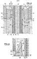
- FIG. 1 For the sake of simplification, only part of the casting basin 1 supplying the die of the invention is shown in FIG. 1, in liquid iron F.
- the casting basin 1 is contained in a metal case or envelope 2 internally coated with a thick refractory lining 3, for example of the silico-aluminous type, and it comprises at its lower part, which is moreover the only one shown in FIG. 1, a vertical pouring orifice 4, of cylindrical shape and of axis XX, inside which is mounted the upper end or head of the die 6, as well as a core 8 which defines with this die a tubular casting space 10.
- a vertical pouring orifice 4 of cylindrical shape and of axis XX, inside which is mounted the upper end or head of the die 6, as well as a core 8 which defines with this die a tubular casting space 10.
- the core 8 which is made of graphite and is coaxial with the pouring orifice, passes right through the pouring basin 1 and is suspended at its upper part, bearing on the body 2, by known means, not shown, for example those described in FR patent No. 2 415 501.
- this core 8 is hollow and internally includes a heating device, for example an inductor 12 in the form of a coil, made of copper, helically wound and internally cooled by water, or a heating resistance.
- the die 6 is also made of graphite. It is tubular and coaxial with the core 8, that is to say with an axis XX, and it surrounds the core 8 by delimiting with it the narrow tubular space 10 whose width corresponds to the thickness of the wall of the tube T to flow.
- the die 6, the height of which is for example 25 cm for the casting of a cast iron tube T, with an external diameter of 170 mm and a thickness of 5 mm, is supported at its lower end by a flange 9 suspended from the body 2 of the neck pelvis tied by tie rods 14.
- the flange 9 also supports a cooling jacket 15, coaxial with the die 6 and the core 8, which is in close contact with the outer wall of this die between the body 2 of the tapping basin, that is to say the outlet of the pouring orifice 4, and the flange 9.
- This cooling jacket 15 is shown diagrammatically in the form of a water circulation sleeve with conduits 16 and 13 for entering and leaving the water , but it is obvious that it can comprise, in accordance with patent FR 2 415 501, between the water circulation sleeve and the die 6, a coolant metal jacket with low melting point in order to ensure contact better thermal and, therefore, a perfect evacuation of calories.
- the installation further comprises a device for extracting, or extracting, the cast T-tube, consisting for example of two pairs of rollers 18 and 20 with horizontal axes, applied to the outer wall of the cast T-tube, symmetrically with respect to axis XX. Two of these rollers, located on the same side of the axis XX, are connected by a transmission chain 19 and driven in rotation, step by step, that is to say with stopping times, by a motor-reducer group 21.
- the exit of the solidified tube T from the tubular space 10 is carried out step by step.
- the die 6 comprises a hollow cylindrical body 7 of constant wall thickness, which is extended at its upper part by a head 17 fitted in the pouring orifice 4.
- the composite head 17 has a thin or narrow annular lip 22, connecting by a wide rounded 23, with the thick body 7, but in one piece with him, in graphite.
- This connection takes place exactly at the mouth of the pouring orifice 4, that is to say in the plane of the contact P (drawn in phantom) between the outer face of the metal case 2 and the upper end of the cooling jacket 15. Consequently, over its entire height, the thin annular lip 22 has, inside the pouring orifice 4, a thickness substantially less than that of the body 7 of the die 6, at the outside this orifice. At its upper part, the lip 22 has a thickness which is a fraction of that of the cooled part 7 of the die 6.
- the lip 22 is frustoconical but, as its conicity is very small, it is almost over its entire height that its thickness is a fraction of that of the cooled body 7.
- the lip 22 has a thickness at most equal to 1/3 of the thickness of the body 7, just before the rounded from its connection with this body, and an axial dimension at least equal to the thickness of the body 7 of the die and currently equal to 1.5 times this thickness.
- the lip 22 is surrounded by a refractory ring 24, for example made of silico-aluminous material, having good thermal insulation characteristics.
- the ring 24 is adjusted on the lip 22 of which it matches the external profile and constitutes, with this lip, the composite head 17 of the die 6.
- the shape and the width of the ring 24 allow this head to be adjusted on the internal wall of the orifice 4 and thus of authorizing the flow of the liquid iron only between the lip 22 and the core 8.
- the thin annular lip has its upper end in direct contact with the liquid iron F contained in the casting basin 1 and is connected with the thick body 7 of the die 6, just at the upper limit of the energetic cooling of this die 6 through the cooling jacket 15.
- the upper horizontal and flat edge 25 of the ring 24, which is flush with the upper end of the lip 22, is also in contact with the liquid iron F of the basin 1.
- its lower edge is in contact with the cylindrical body 7 and with the rounded 23 connecting the lip to this body in the plane P.
- Cooling can only come from the cooling jacket 15.
- a cooling flow passes through the conductive graphite of the lip 22 and of the body 7, but cannot pass through the refractory material of the ring 24.
- the flow of cooling created between the liquid iron and the cooling jacket follow the paths indicated by the arrow lines f 1 in dotted lines and f 2 in broken lines in FIG. 2.
- the liquid iron contained in the annular space 10, inside the lip 22 and the pouring orifice 4, above the plane P is relatively little cooled. We can even consider that it undergoes practically no cooling.
- the lip 22 is not only in one piece with the body 7, but also its internal surface is exactly in the extension of the internal cylindrical wall 26 of this body 7 (and therefore carries the same reference numeral 26 ), so that the die has a continuous wall over its entire height and in particular between the area hot located in the pouring orifice 4, above the plane P, and the zone cooled by the casing 11, below the plane P.
- This wall continuity 26 in graphite offered to liquid cast iron is particularly advantageous since 'It exists at the start of the casting and is maintained during the latter, while the graphite die 6 heats up in contact with the liquid iron and consequently expands uniformly.
- Solidification begins at the upper limit P of influence of the cooling jacket 15 to be complete at the lower end of the die 6, that is to say near the outlet of the latter. .
- a die 36 of the prior art comprises a head 37 of frustoconical shape which , to the right of the body 2, has the same width as the body of the die and thins in the direction of the casting basin.
- the thickness of solidified cast iron FS can reach half the width of the annular space 10 and even the whole of this space, until it is blocked. Below the plane P, the cooling of the liquid iron is much more vigorous since the path of the flow of calories f 2 to the cooling jacket 15 is much more direct, much shorter.
- the plane P of separation between these two cooling zones therefore marks a clear difference in thickness of solidified cast iron, which at 28 presents a breakthrough at each extraction pass.
- the composite head 17 of the die 6 of FIGS. 1 and 2 remains hot and avoids the cooling of the cast iron in this zone of the die, so that no solidification begins above the plane P. It is only below the plane P that solidification begins. The aforementioned serious defect is therefore avoided.
- the head 17 of the die is robust, offers no mechanical fragility because the ring 24 protects and externally strengthens the thinned lip 22, and thus ensures the continuity of the thickness of the die, including in the zone contained inside the pouring orifice 4.
- a composite hot head of the die can be produced in other ways. bearing, on the one hand a graphite part of small section, providing a cylindrical wall continuity to the flow of the cast iron in the annular space 10 and offering a small section for passage of calories in the direction of the cooling jacket 15, and on the other hand an insulating refractory part, for example silico-aluminous.
- the limit between the composite head and the body 7 of the die must remain the horizontal plane P, the body 7 having the same height as the envelope 15.
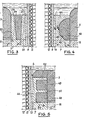
- the die head comprises, above the plane P, two thin concentric annular lips, respectively outer 32 and inner 22.
- the lips 22 and 32 are made of graphite since they are the continuity of the thick tubular body 7 of the Faculty.
- the outer surface of the outer lip 32 is cylindrical to be applied exactly against the wall of the pouring orifice, while the facing surfaces of the two lips are slightly frustoconical and are separated by an insulating refractory ring 34, made of silico material -aluminous, in close contact with each of them, which of course is flush with their upper ends, in the same horizontal plane.
- the refractory lining extends above the head and is connected with the internal wall of the internal lip 22.
- the refractory ring 34 constitutes an obstacle preventing the passage of calories while ensuring mechanical reinforcement of the hot die head.
- the composite die head comprises above the plane P a lip 42 whose hollowed out outer face 43 is concave in a semi-toric recess profile, which forms a rim or upper widening 44 joining the internal wall of the pouring orifice and a housing for a refractory ring, silico-aluminous, 45 with semi-toric conjugate profile and with cylindrical external profile adjusted to the cylindrical internal profile of the pouring orifice 4
- the rim 44 occupies the same annular width as the body 7 located below the plane P. But this upper rim 44 of great width, in contact with the liquid cast iron contained in the casting basin 1, is substantially thinned.
- the flow f 1 of calorie drive towards the cooling jacket 15 cannot spread over the entire annular width of this upper rim nor go directly towards the cooling jacket 15.
- the flow f 1 must bypass the refractory ring 45 and cross a narrow annular section ab, between the refractory ring 45 and the tubular space 10 Therefore, the entrainment of calories by the flow f 1 is weak.
- FIG. 5 represents an embodiment of this type.
- a graphite composite head has a thin internal lip 46, the hollowed out outer surface of which delimits two housings of rectangular section, which are filled by two refractory rings 48 and 49, concentric and of the same cylindrical shape (rectangular profile nearly).
- the two rings 48 and 49 are separated by a horizontal partition 50 made of graphite, formed by a circumferential fin of the lip 46 in contact with the refractory lining 3 and, consequently, not capable of providing a passage for calories.
- a horizontal partition 50 made of graphite
- the lip 46 has an upper rim or planar partition 52, which gives the graphite head a meridian profile at F.
- the upper section of this meridian profile at F can be either covered with refractory lining 3, if the latter is connected by a rounding (in solid lines) with the internal wall of the graphite lip 46, or in contact with liquid cast iron if the rounded connection is made along the line in broken lines, in the extension of the peripheral edges of the partitions 50, 52.
- the lip 46 can be devoid of an upper rim 52; the upper insulating ring 49 is then, at its upper part, in contact with the lining 3, which gives the graphite lip a T-meridian profile.
- the passage section offered to the flow f 1 for discharging calories to the cooling jacket 15 remains limited to the thinned vertical tubular lip 46 of the head.
- the composite head can also include other arrangements of graphite lip and ring opposing the passage of calories, depending on the ins tallations.
- the insulating ring 45 (fig. 4), 48, 49 (fig. 5)
- the rings 45, 48, 49 can be made of alumina fibers while the ring 24 can be made of silico-aluminous concrete, the latter being much less insulating than the alumina fibers.
- the height of a lip 32, 42, 46 above the plane P, and its average radial width are similar to those of the lip 22 in FIGS. 1 and 2.
- the invention has been described for continuous vertical downward casting, it also applies to continuous upward casting, the die head becoming the die "foot” and being immersed in the cast iron bath located at the lower part of the installation; it also applies to horizontal continuous casting (the X-X axis being horizontal) or to inclined continuous casting (the X-X axis being oblique).
Landscapes
- Engineering & Computer Science (AREA)
- Mechanical Engineering (AREA)
- Continuous Casting (AREA)
- Molds, Cores, And Manufacturing Methods Thereof (AREA)
- Rigid Pipes And Flexible Pipes (AREA)
- Metal Extraction Processes (AREA)
- Extrusion Moulding Of Plastics Or The Like (AREA)
- Refinement Of Pig-Iron, Manufacture Of Cast Iron, And Steel Manufacture Other Than In Revolving Furnaces (AREA)
- Shaping Of Tube Ends By Bending Or Straightening (AREA)
- Manufacture Of Alloys Or Alloy Compounds (AREA)
- Medicines Containing Antibodies Or Antigens For Use As Internal Diagnostic Agents (AREA)
- Treatment Of Steel In Its Molten State (AREA)
- Record Information Processing For Printing (AREA)
- Mechanical Pencils And Projecting And Retracting Systems Therefor, And Multi-System Writing Instruments (AREA)
- Holo Graphy (AREA)
- Building Environments (AREA)
- Casting Support Devices, Ladles, And Melt Control Thereby (AREA)
- Moulds For Moulding Plastics Or The Like (AREA)
- Perforating, Stamping-Out Or Severing By Means Other Than Cutting (AREA)
Priority Applications (1)
| Application Number | Priority Date | Filing Date | Title |
|---|---|---|---|
| AT83102221T ATE19363T1 (de) | 1982-03-12 | 1983-03-07 | Vorrichtung und giessform zum stranggiessen von duennwandigen giesseisernen roehren. |
Applications Claiming Priority (2)
| Application Number | Priority Date | Filing Date | Title |
|---|---|---|---|
| FR8204195A FR2523006A1 (fr) | 1982-03-12 | 1982-03-12 | Filiere tubulaire pour la coulee continue d'un tube, a paroi mince, en fonte |
| FR8204195 | 1982-03-12 |
Publications (2)
| Publication Number | Publication Date |
|---|---|
| EP0088980A1 true EP0088980A1 (de) | 1983-09-21 |
| EP0088980B1 EP0088980B1 (de) | 1986-04-23 |
Family
ID=9271922
Family Applications (1)
| Application Number | Title | Priority Date | Filing Date |
|---|---|---|---|
| EP83102221A Expired EP0088980B1 (de) | 1982-03-12 | 1983-03-07 | Vorrichtung und Giessform zum Stranggiessen von dünnwandigen giesseisernen Röhren |
Country Status (29)
| Country | Link |
|---|---|
| US (1) | US4506723A (de) |
| EP (1) | EP0088980B1 (de) |
| JP (1) | JPS58168456A (de) |
| KR (1) | KR880002066B1 (de) |
| AT (1) | ATE19363T1 (de) |
| AU (1) | AU554716B2 (de) |
| BE (1) | BE896139A (de) |
| BR (1) | BR8301236A (de) |
| CA (1) | CA1201868A (de) |
| CH (1) | CH654503A5 (de) |
| CZ (1) | CZ279230B6 (de) |
| DD (1) | DD208564A5 (de) |
| DE (1) | DE3363143D1 (de) |
| EG (1) | EG15354A (de) |
| ES (1) | ES520523A0 (de) |
| FR (1) | FR2523006A1 (de) |
| GB (1) | GB2116466B (de) |
| HR (1) | HRP930747B1 (de) |
| IN (1) | IN158610B (de) |
| IT (2) | IT8353050V0 (de) |
| MX (1) | MX159487A (de) |
| PL (1) | PL135939B1 (de) |
| RO (1) | RO86288B (de) |
| SE (1) | SE8301221L (de) |
| SI (1) | SI8310507A8 (de) |
| SK (1) | SK278292B6 (de) |
| SU (1) | SU1215607A3 (de) |
| UA (1) | UA6078A1 (de) |
| YU (1) | YU44096B (de) |
Cited By (2)
| Publication number | Priority date | Publication date | Assignee | Title |
|---|---|---|---|---|
| DE19918228A1 (de) * | 1999-04-22 | 2000-10-26 | Daimler Chrysler Ag | Verfahren zum Herstellen von Rohlingen für Zylinderlaufbüchsen |
| EP2336094A1 (de) | 2009-12-21 | 2011-06-22 | Mapei S.p.A. | Starke Weichmacher für Beton- und Zementmaterialien und Herstellungsverfahren dafür |
Families Citing this family (10)
| Publication number | Priority date | Publication date | Assignee | Title |
|---|---|---|---|---|
| JPS59215251A (ja) * | 1983-05-23 | 1984-12-05 | Kuroki Kogyosho:Kk | 金属パイプの連続鋳造方法 |
| FR2557820B1 (fr) * | 1984-01-10 | 1987-05-07 | Pont A Mousson | Dispositif d'alimentation en metal liquide pour installation de coulee continue verticale d'un tube metallique, notamment en fonte |
| GB8401976D0 (en) * | 1984-01-25 | 1984-02-29 | Imi Refiners Ltd | Casting apparatus |
| JPS61135452A (ja) * | 1984-12-06 | 1986-06-23 | Nippon Light Metal Co Ltd | 中空ビレットの連続鋳造装置 |
| FR2573683B1 (fr) * | 1984-11-26 | 1987-01-02 | Pont A Mousson | Installation d'alimentation en metal liquide avec controle de temperature du metal liquide pour la coulee continue d'un tuyau en fonte |
| JP2692142B2 (ja) * | 1988-06-10 | 1997-12-17 | 石川島播磨重工業株式会社 | 半凝固金属スラリー製造装置 |
| FR2751250B1 (fr) * | 1996-07-17 | 1998-08-21 | Pont A Mousson | Dispositif de bridage d'une table de coulee d'une machine de coulee continue verticale de pieces, en particulier de tubes, en fonte |
| US20110042033A1 (en) * | 2005-11-30 | 2011-02-24 | Advanced Intellectual Holdings Pty Ltd | Apparatus for laying elongate elements |
| BR102017015433B1 (pt) * | 2017-07-18 | 2023-04-18 | Tupy S.A. | Sistema para a produção de um componente de ferro por lingotamento contínuo |
| CN114425608B (zh) * | 2022-01-11 | 2025-08-26 | 西安格美金属材料有限公司 | 高温合金管熔铸器 |
Citations (2)
| Publication number | Priority date | Publication date | Assignee | Title |
|---|---|---|---|---|
| FR1480828A (fr) * | 1966-03-16 | 1967-05-12 | Anaconda American Brass Co | Appareil et procédé de coulée continue de tubes métalliques |
| FR2415501A1 (fr) * | 1978-01-27 | 1979-08-24 | Pont A Mousson | Procede et installation pour la coulee continue de produits tubulaires |
Family Cites Families (1)
| Publication number | Priority date | Publication date | Assignee | Title |
|---|---|---|---|---|
| GB1235112A (en) * | 1967-06-19 | 1971-06-09 | Consolidus Ltd | Improvements relating to continuous casting apparatus |
-
1982
- 1982-03-12 FR FR8204195A patent/FR2523006A1/fr active Granted
-
1983
- 1983-02-10 GB GB08303711A patent/GB2116466B/en not_active Expired
- 1983-02-22 US US06/468,739 patent/US4506723A/en not_active Expired - Lifetime
- 1983-03-01 AU AU11937/83A patent/AU554716B2/en not_active Ceased
- 1983-03-03 SI SI8310507A patent/SI8310507A8/sl unknown
- 1983-03-03 YU YU507/83A patent/YU44096B/xx unknown
- 1983-03-07 AT AT83102221T patent/ATE19363T1/de not_active IP Right Cessation
- 1983-03-07 SE SE8301221A patent/SE8301221L/xx not_active Application Discontinuation
- 1983-03-07 DE DE8383102221T patent/DE3363143D1/de not_active Expired
- 1983-03-07 EP EP83102221A patent/EP0088980B1/de not_active Expired
- 1983-03-10 RO RO110286A patent/RO86288B/ro unknown
- 1983-03-10 CZ CS831654A patent/CZ279230B6/cs unknown
- 1983-03-10 IN IN299/CAL/83A patent/IN158610B/en unknown
- 1983-03-10 SK SK1654-83A patent/SK278292B6/sk unknown
- 1983-03-10 PL PL1983240969A patent/PL135939B1/pl unknown
- 1983-03-10 JP JP58039989A patent/JPS58168456A/ja active Granted
- 1983-03-11 CA CA000423456A patent/CA1201868A/en not_active Expired
- 1983-03-11 MX MX196547A patent/MX159487A/es unknown
- 1983-03-11 UA UA3571173A patent/UA6078A1/uk unknown
- 1983-03-11 DD DD83248750A patent/DD208564A5/de not_active IP Right Cessation
- 1983-03-11 SU SU833571173A patent/SU1215607A3/ru active
- 1983-03-11 BE BE0/210304A patent/BE896139A/fr not_active IP Right Cessation
- 1983-03-11 ES ES520523A patent/ES520523A0/es active Granted
- 1983-03-11 IT IT8353050U patent/IT8353050V0/it unknown
- 1983-03-11 CH CH1354/83A patent/CH654503A5/fr not_active IP Right Cessation
- 1983-03-11 BR BR8301236A patent/BR8301236A/pt not_active IP Right Cessation
- 1983-03-12 KR KR1019830000995A patent/KR880002066B1/ko not_active Expired
- 1983-03-12 EG EG83166A patent/EG15354A/xx active
- 1983-05-11 IT IT67275/83A patent/IT1159367B/it active
-
1993
- 1993-04-02 HR HRP-507/83A patent/HRP930747B1/xx not_active IP Right Cessation
Patent Citations (2)
| Publication number | Priority date | Publication date | Assignee | Title |
|---|---|---|---|---|
| FR1480828A (fr) * | 1966-03-16 | 1967-05-12 | Anaconda American Brass Co | Appareil et procédé de coulée continue de tubes métalliques |
| FR2415501A1 (fr) * | 1978-01-27 | 1979-08-24 | Pont A Mousson | Procede et installation pour la coulee continue de produits tubulaires |
Cited By (3)
| Publication number | Priority date | Publication date | Assignee | Title |
|---|---|---|---|---|
| DE19918228A1 (de) * | 1999-04-22 | 2000-10-26 | Daimler Chrysler Ag | Verfahren zum Herstellen von Rohlingen für Zylinderlaufbüchsen |
| DE19918228C2 (de) * | 1999-04-22 | 2002-08-14 | Daimler Chrysler Ag | Verfahren zum Herstellen von Rohlingen für Zylinderlaufbüchsen |
| EP2336094A1 (de) | 2009-12-21 | 2011-06-22 | Mapei S.p.A. | Starke Weichmacher für Beton- und Zementmaterialien und Herstellungsverfahren dafür |
Also Published As
Similar Documents
| Publication | Publication Date | Title |
|---|---|---|
| EP0088980B1 (de) | Vorrichtung und Giessform zum Stranggiessen von dünnwandigen giesseisernen Röhren | |
| EP0311506B1 (de) | Schmelztiegel für einen Induktionsofen | |
| FR2548954A1 (fr) | Procede pour realiser une enceinte etanche | |
| FR2617570A1 (fr) | Dispositif anti-stratification thermique pour tuyau d'alimentation de generateur de vapeur | |
| EP0151723B1 (de) | Metallzufuhr beim vertikalen Stranggiessen von Metallröhren, hauptsächlich aus Gusseisen | |
| CH682390A5 (fr) | Conteneur pour le transport d'un matériau en état solide. | |
| FR2487494A1 (fr) | Accumulateur de chaleur latente assurant un passage regulier du fluide echangeur de chaleur a travers le fluide accumulateur de chaleur | |
| FR2706794A1 (en) | Casting gutter (spout, launder) for producing metallic objects, particularly cast-iron pipes | |
| CA2251020C (fr) | Lingotiere de coulee continue en charge verticale des metaux | |
| FR2547517A1 (fr) | Installation de coulee continue verticale a filiere a entree chaude pour la coulee de tubes metalliques, notamment en fonte | |
| FR2754748A1 (fr) | Piece de transfert et son procede de fabrication | |
| CA1180878A (fr) | Dispositif de support et de centrage d'un noyau dans une filiere de coulee continue d'un tube | |
| FR2647698A1 (fr) | Dispositif d'alimentation en metal liquide d'une installation de coulee continue de produits minces et procede pour sa mise en oeuvre | |
| FR2736289A1 (fr) | Ensemble plaque-busette interne comportant une zone de moindre resistance | |
| EP0958073A1 (de) | Verfahren und anlage stranggiessen von metall | |
| EP0868952B1 (de) | Strangiesskokille für Metalle | |
| FR2516500A1 (fr) | Installation pour l'obtention de gouttes de verre a partir d'un verre fondu contenant des dechets radioactifs | |
| CH144063A (fr) | Procédé de coulage centrifuge de métal dans un moule rotatif et cuve de versement pour la mise en oeuvre de ce procédé. | |
| BE532569A (de) | ||
| FR2458777A1 (fr) | Cubilot a coulee continue | |
| BE420625A (de) | ||
| BE639366A (de) | ||
| BE381530A (de) | ||
| FR2628521A1 (fr) | Inhibiteur d'ecoulement du laitier metallurgique | |
| BE527841A (de) |
Legal Events
| Date | Code | Title | Description |
|---|---|---|---|
| PUAI | Public reference made under article 153(3) epc to a published international application that has entered the european phase |
Free format text: ORIGINAL CODE: 0009012 |
|
| AK | Designated contracting states |
Designated state(s): AT BE CH DE GB IT LI NL SE |
|
| 17P | Request for examination filed |
Effective date: 19830927 |
|
| RBV | Designated contracting states (corrected) |
Designated state(s): AT BE CH DE IT LI NL SE |
|
| GRAA | (expected) grant |
Free format text: ORIGINAL CODE: 0009210 |
|
| AK | Designated contracting states |
Kind code of ref document: B1 Designated state(s): AT BE CH DE IT LI NL SE |
|
| REF | Corresponds to: |
Ref document number: 19363 Country of ref document: AT Date of ref document: 19860515 Kind code of ref document: T |
|
| ITF | It: translation for a ep patent filed | ||
| REF | Corresponds to: |
Ref document number: 3363143 Country of ref document: DE Date of ref document: 19860528 |
|
| PLBE | No opposition filed within time limit |
Free format text: ORIGINAL CODE: 0009261 |
|
| STAA | Information on the status of an ep patent application or granted ep patent |
Free format text: STATUS: NO OPPOSITION FILED WITHIN TIME LIMIT |
|
| 26N | No opposition filed | ||
| ITTA | It: last paid annual fee | ||
| EAL | Se: european patent in force in sweden |
Ref document number: 83102221.5 |
|
| PGFP | Annual fee paid to national office [announced via postgrant information from national office to epo] |
Ref country code: NL Payment date: 19970224 Year of fee payment: 15 Ref country code: AT Payment date: 19970224 Year of fee payment: 15 |
|
| PGFP | Annual fee paid to national office [announced via postgrant information from national office to epo] |
Ref country code: DE Payment date: 19970319 Year of fee payment: 15 |
|
| PGFP | Annual fee paid to national office [announced via postgrant information from national office to epo] |
Ref country code: SE Payment date: 19970325 Year of fee payment: 15 Ref country code: CH Payment date: 19970325 Year of fee payment: 15 |
|
| PGFP | Annual fee paid to national office [announced via postgrant information from national office to epo] |
Ref country code: BE Payment date: 19970410 Year of fee payment: 15 |
|
| PG25 | Lapsed in a contracting state [announced via postgrant information from national office to epo] |
Ref country code: AT Free format text: LAPSE BECAUSE OF NON-PAYMENT OF DUE FEES Effective date: 19980307 |
|
| PG25 | Lapsed in a contracting state [announced via postgrant information from national office to epo] |
Ref country code: SE Free format text: LAPSE BECAUSE OF NON-PAYMENT OF DUE FEES Effective date: 19980308 |
|
| PG25 | Lapsed in a contracting state [announced via postgrant information from national office to epo] |
Ref country code: LI Free format text: LAPSE BECAUSE OF NON-PAYMENT OF DUE FEES Effective date: 19980331 Ref country code: CH Free format text: LAPSE BECAUSE OF NON-PAYMENT OF DUE FEES Effective date: 19980331 Ref country code: BE Free format text: LAPSE BECAUSE OF NON-PAYMENT OF DUE FEES Effective date: 19980331 |
|
| BERE | Be: lapsed |
Owner name: PONT-A-MOUSSON S.A. Effective date: 19980331 |
|
| PG25 | Lapsed in a contracting state [announced via postgrant information from national office to epo] |
Ref country code: NL Free format text: LAPSE BECAUSE OF NON-PAYMENT OF DUE FEES Effective date: 19981001 |
|
| REG | Reference to a national code |
Ref country code: CH Ref legal event code: PL |
|
| NLV4 | Nl: lapsed or anulled due to non-payment of the annual fee |
Effective date: 19981001 |
|
| PG25 | Lapsed in a contracting state [announced via postgrant information from national office to epo] |
Ref country code: DE Free format text: LAPSE BECAUSE OF NON-PAYMENT OF DUE FEES Effective date: 19981201 |
|
| EUG | Se: european patent has lapsed |
Ref document number: 83102221.5 |