EP0090107A1 - Konvergenzeinheit für Farbkathodenstrahlröhre - Google Patents
Konvergenzeinheit für Farbkathodenstrahlröhre Download PDFInfo
- Publication number
- EP0090107A1 EP0090107A1 EP82301683A EP82301683A EP0090107A1 EP 0090107 A1 EP0090107 A1 EP 0090107A1 EP 82301683 A EP82301683 A EP 82301683A EP 82301683 A EP82301683 A EP 82301683A EP 0090107 A1 EP0090107 A1 EP 0090107A1
- Authority
- EP
- European Patent Office
- Prior art keywords
- core
- limbs
- convergence unit
- windings
- cathode ray
- Prior art date
- Legal status (The legal status is an assumption and is not a legal conclusion. Google has not performed a legal analysis and makes no representation as to the accuracy of the status listed.)
- Granted
Links
Images

Classifications
-
- H—ELECTRICITY
- H01—ELECTRIC ELEMENTS
- H01J—ELECTRIC DISCHARGE TUBES OR DISCHARGE LAMPS
- H01J29/00—Details of cathode-ray tubes or of electron-beam tubes of the types covered by group H01J31/00
- H01J29/46—Arrangements of electrodes and associated parts for generating or controlling the ray or beam, e.g. electron-optical arrangement
- H01J29/70—Arrangements for deflecting ray or beam
- H01J29/701—Systems for correcting deviation or convergence of a plurality of beams by means of magnetic fields at least
- H01J29/702—Convergence correction arrangements therefor
- H01J29/705—Dynamic convergence systems
-
- H—ELECTRICITY
- H01—ELECTRIC ELEMENTS
- H01J—ELECTRIC DISCHARGE TUBES OR DISCHARGE LAMPS
- H01J2229/00—Details of cathode ray tubes or electron beam tubes
- H01J2229/56—Correction of beam optics
- H01J2229/568—Correction of beam optics using supplementary correction devices
- H01J2229/5681—Correction of beam optics using supplementary correction devices magnetic
- H01J2229/5687—Auxiliary coils
Definitions
- This invention relates to a convergence unit for an in-line colour cathode ray tube.
- the "red”, “green” and “blue” electron beams lie in a common plane as they travel down the neck of the cathode ray tube to the deflection yoke.
- the so-called self-converging yokes are adequate to preserve colour convergence at the CRT screen.
- misconvergence of the CRT is readily apparent to the viewer and accordingly some means for converging the three beams must be provided.
- the convergence units used with the older delta-type cathode ray tubes are unsuitable due to the different relative positions of the three beams.
- two 4-pole and two 6-pole magnetic fields are produced, for example, by means of a toroidal magnetic core surrounding the neck of the CRT and carrying a plurality of windings: the 4-pole field is used to produce horizontal and vertical shifting of the outer beams in opposite directions while the 6-pole field is used to produce horizontal and vertical shifting of the outer beams in the same direction.
- the 4-pole field is used to produce horizontal and vertical shifting of the outer beams in opposite directions
- the 6-pole field is used to produce horizontal and vertical shifting of the outer beams in the same direction.
- a convergence unit for an in-line cathode ray tube comprises a pair of E-shaped magnetic cores each carrying a pair of independent windings by means of which a magnetic field is used to shift one or both of the outer beams of the cathode ray tube to correct for misconvergence and is characterised in that each E-shaped core has two limbs extending from a central pole piece to end pole pieces, the length of the limbs being larger than the lengths of the pole pieces and the windings being located around said limbs with the axis of each winding extending substantially parallel to a tangent to the cathode ray tube neck whereby magnetic fields due to individual turns reinforce the magnetic fields between the pole pieces.
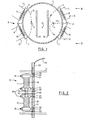
- an in-line colour cathode ray tube has a neck portion 1 within which are located the "red”, “green” and “blue” electron beams 2, 3 and 4 respectively.
- the "red”, “green” and “blue” electron beams 2, 3 and 4 In order to ensure correct beam convergence at the shadow mask and screen, not shown, it is necessary to be able to shift beams 2 and 4 vertically and/or horizontally with respect to the central beam 3.
- two E-cores 5 are provided, one on each side of the tube neck.
- Each E-core has end pole pieces 6 and 7 and a central pole piece 8 extending towards the neck 1 with limbs or arms 9 and 10 carrying windings 11 and 12 respectively.
- a vertical field can be produced at the region of the outer beam as represented by field 13.
- a horizontal field can be produced at the region of the outer beam as represented by field 14.
- Fields 13 and 14 cause shifting of the outer beams in the horizontal and vertical directions respectively.
- Magnetic shields 15 and 16 shield the central electron beam 3 from the influence of the magnetic fields produced by means of the E-cores 5 and windings 11 and 12.
- the efficiency (or sensitivity) of the convergence unit depends on a number of factors including the geometry and material of the E-cores, the design and position of the internal magnetic shields, the size of the windings and number of turns.
- the E-cores 5 are formed with their limbs longer than their pole pieces with the windings extending along the limbs substantially parallel to a tangent to the neck.
- the length of the limbs 9 and 10 can be readily optimized for the particular cathode ray tube to be converged, particularly where strip-shaped soft-magnetic material such as permalloy and mumetal are used. In this case, it is preferred if the width of the strip extends parallel to the electron beam paths since this will increase the sensitivity.
- the senstivities for convergence correction are different at the centre and in the corners of the screen. Horizontal correction is more sensitive in the corner and less sensitive in the centre whereas vertical correction is less sensitive in the corners and more sensitive in the centre. On the assumption that horizontal and vertical convergence errors are equally likely, then the best overall efficiency is achieved if the horizontal and vertical sensitivities are equal. (High sensitivity is achieved if the energy factor LI 2 is a minimum where L is the coil inductance and I the current required to shift the convergence by 1 mm.) Since there should be no or little convergence error to correct at the centre of the screen, the balance should be achieved in the corners by appropriate choice of the lengths of the cross pieces 9 and 10 of the E-cores. Experimental results have shown that with a CRT neck outside diameter of 29 mm and beam separation of 7 mm an optimum balance can be achieved with limbs or arms 13 mm long. To increase the vertical sensitivity relative to the horizontal sensitivity, the arm lengths should be increased.
- Table I illustrates the horizontal and vertical correction energy factor (in microjoules/mm shift) for the centre and corner areas of a CRT having the dimensions specified above.
- FIG 2 which is a part-sectional view in the Direction II-II, Figure 1, illustrates how the E-cores 5 could be mounted on a printed circuit board 17 orthogonal to and surrounding the neck 1.
- Each coil 11, 12 is wound on a bobbin 18 of non-magnetic plastics material.
- Posts 19 allow the windings to be anchored to the bobbins 18 from which they can be lead to apertures 20 in the circuit board 17.
- Each bobbin 18 has mounting posts 21 which mate with corresponding apertures 22 in the circuit board 17.
- strip shaped arms or limbs 9 and 10 constituting the cores extend through bores within the bobbins 18.
- Printed wiring on the circuit board 17 leads to an edge connector 23 having a lead 24 by which current can be supplied to each of the four independent windings.
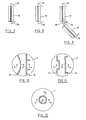
- FIGs 3 and 4 show an alternative arrangement for the E-core windings 11 and 12 shown in Figure 1.
- winding 11' is wound as two equal halves over both arms 9 and 10 of the E-core but is connected or wound to result in a horizontal field 14.
- Winding 12' is wound as two equal halves over both arms 9 and 10 and is connected or wound to result in a vertical field 13 as shown in Figure 4. It will be appreciated that Figures 3 and 4 are shown separately to clarify the winding arrangement: in practice each E-core will consist of two windings 11' and 12'.
- Figure 5 serves to illustrate a problem which can arise with the arrangement of Figure 1 where two independent coils are wound on different parts of the same E-core. If the coil 11 is energized as shown, then the pole adjacent the un-energized part of the core will be spread out somewhat. To prevent this, a second coil 11a in series with the first coil 11 but wound in the opposite sense is provided on the lower part 10 of the E-core with half the number of turns of coil 11 as shown in Figure 6. This will have the effect of restricting the poles to the desired positions.
- the coils can be wound directly on the E-cores (in which case pre-formed ferrite material can be used) or a pair of prewound double wound bobbins could be used, one prewound winding being half the number of turns of the other.
- FIGs 7 to 9 illustrate how prewound bobbins 18 may be provided with strip shaped core pieces.
- each bobbin 18 is supplied with a pair of L-shaped strips 25.
- Each E-core would consist of two such bobbin combinations located side by side. Since no bending is required, pre-formed ferrite core pieces could be used rather than mumetal strips.
- a single L-shaped bobbin 26 is used which is bent at 27 after insertion in the bobbin 18: again two such bobbin combinations would be required to form an E-core.
- a single piece of strip shaped material 28 is first bent at 29 to form the eventual central pole piece of the E-core. After threading the bobbins 18 onto the strip 28, the strip is bent at 30 and 31 to form the end pole pieces.
- Figures 10 and 11 each show two different shapes for the magnetic shield plates 15, 16, 17 and 18. In practice the same shaped plates would be used on each side of the central beam 3.
- Figure 12 shows an alternative arrangement in which the central beam 3 is completely surrounded by a shield 32: although a cylindrical shield is shown, any other convenient shape could be employed.
- Optimum sensitivity can be obtained by positioning the windings close to the tube with the fields due to the individual turns reinforcing the field between the pole pieces and selecting the lengths of the arms for the particular CRT employed.
Landscapes
- Video Image Reproduction Devices For Color Tv Systems (AREA)
Priority Applications (4)
| Application Number | Priority Date | Filing Date | Title |
|---|---|---|---|
| EP82301683A EP0090107B1 (de) | 1982-03-31 | 1982-03-31 | Konvergenzeinheit für Farbkathodenstrahlröhre |
| DE8282301683T DE3271747D1 (en) | 1982-03-31 | 1982-03-31 | Convergence unit for in-line colour cathode ray tube |
| US06/454,397 US4470029A (en) | 1982-03-31 | 1982-12-29 | Convergence unit for in-line color cathode ray tube |
| JP58039315A JPS58173990A (ja) | 1982-03-31 | 1983-03-11 | コンバ−ジェンス装置 |
Applications Claiming Priority (1)
| Application Number | Priority Date | Filing Date | Title |
|---|---|---|---|
| EP82301683A EP0090107B1 (de) | 1982-03-31 | 1982-03-31 | Konvergenzeinheit für Farbkathodenstrahlröhre |
Publications (2)
| Publication Number | Publication Date |
|---|---|
| EP0090107A1 true EP0090107A1 (de) | 1983-10-05 |
| EP0090107B1 EP0090107B1 (de) | 1986-06-18 |
Family
ID=8189624
Family Applications (1)
| Application Number | Title | Priority Date | Filing Date |
|---|---|---|---|
| EP82301683A Expired EP0090107B1 (de) | 1982-03-31 | 1982-03-31 | Konvergenzeinheit für Farbkathodenstrahlröhre |
Country Status (4)
| Country | Link |
|---|---|
| US (1) | US4470029A (de) |
| EP (1) | EP0090107B1 (de) |
| JP (1) | JPS58173990A (de) |
| DE (1) | DE3271747D1 (de) |
Cited By (1)
| Publication number | Priority date | Publication date | Assignee | Title |
|---|---|---|---|---|
| GB2202082A (en) * | 1986-12-27 | 1988-09-14 | Sony Corp | Cathode ray tubes |
Families Citing this family (7)
| Publication number | Priority date | Publication date | Assignee | Title |
|---|---|---|---|---|
| US4772826A (en) * | 1986-06-26 | 1988-09-20 | Rca Licensing Corporation | Color display system |
| US4697120A (en) * | 1986-06-26 | 1987-09-29 | Rca Corporation | Color display system with electrostatic convergence means |
| KR910001401B1 (ko) * | 1987-05-25 | 1991-03-04 | 미쯔비시덴끼 가부시끼가이샤 | 편향 요크 |
| JP2518621Y2 (ja) * | 1988-07-06 | 1996-11-27 | 三菱電機株式会社 | 偏向ヨーク装置 |
| US5432401A (en) * | 1992-10-05 | 1995-07-11 | Murata Mfg. Co., Ltd. | Correcting coil of deflection yoke |
| CN1139097C (zh) * | 1995-06-09 | 2004-02-18 | 皇家菲利浦电子有限公司 | 具有行平衡线圈的偏转装置 |
| US20090159703A1 (en) * | 2007-12-24 | 2009-06-25 | Dynamics Inc. | Credit, security, debit cards and the like with buttons |
Citations (3)
| Publication number | Priority date | Publication date | Assignee | Title |
|---|---|---|---|---|
| FR2228293A1 (de) * | 1973-05-04 | 1974-11-29 | Hitachi Ltd | |
| US3866080A (en) * | 1973-08-08 | 1975-02-11 | Rca Corp | Inline electron gun having magnetically permeable plates for enhancing convergence of electron beams |
| EP0002571A1 (de) * | 1977-12-09 | 1979-06-27 | International Business Machines Corporation | Elektromagnetische Einrichtung zur Justierung der seitlichen Konvergenz bei einer Kathodenstrahlröhre |
Family Cites Families (1)
| Publication number | Priority date | Publication date | Assignee | Title |
|---|---|---|---|---|
| DE2612607C3 (de) * | 1976-03-25 | 1984-01-12 | Philips Patentverwaltung Gmbh, 2000 Hamburg | Statische Konvergenzkorrekturvorrichtung in Farbfernsehbildwiedergaberöhren |
-
1982
- 1982-03-31 DE DE8282301683T patent/DE3271747D1/de not_active Expired
- 1982-03-31 EP EP82301683A patent/EP0090107B1/de not_active Expired
- 1982-12-29 US US06/454,397 patent/US4470029A/en not_active Expired - Fee Related
-
1983
- 1983-03-11 JP JP58039315A patent/JPS58173990A/ja active Granted
Patent Citations (3)
| Publication number | Priority date | Publication date | Assignee | Title |
|---|---|---|---|---|
| FR2228293A1 (de) * | 1973-05-04 | 1974-11-29 | Hitachi Ltd | |
| US3866080A (en) * | 1973-08-08 | 1975-02-11 | Rca Corp | Inline electron gun having magnetically permeable plates for enhancing convergence of electron beams |
| EP0002571A1 (de) * | 1977-12-09 | 1979-06-27 | International Business Machines Corporation | Elektromagnetische Einrichtung zur Justierung der seitlichen Konvergenz bei einer Kathodenstrahlröhre |
Non-Patent Citations (1)
| Title |
|---|
| IBM TECHNICAL DISCLOSURE BULLETIN, vol. 24, no. 2, July 1981, pages 1061-1062, Armonk, N.Y. (USA); * |
Cited By (3)
| Publication number | Priority date | Publication date | Assignee | Title |
|---|---|---|---|---|
| GB2202082A (en) * | 1986-12-27 | 1988-09-14 | Sony Corp | Cathode ray tubes |
| US4857796A (en) * | 1986-12-27 | 1989-08-15 | Sony Corporation | Cathode-ray tube with electrostatic convergence means and magnetic misconvergence correcting mechanism |
| GB2202082B (en) * | 1986-12-27 | 1990-09-19 | Sony Corp | Cathode ray tubes |
Also Published As
| Publication number | Publication date |
|---|---|
| EP0090107B1 (de) | 1986-06-18 |
| US4470029A (en) | 1984-09-04 |
| JPS6240919B2 (de) | 1987-08-31 |
| JPS58173990A (ja) | 1983-10-12 |
| DE3271747D1 (en) | 1986-07-24 |
Similar Documents
| Publication | Publication Date | Title |
|---|---|---|
| US4470029A (en) | Convergence unit for in-line color cathode ray tube | |
| KR100464706B1 (ko) | 소정의 각도 범위 내에 권선 공간을 구비한 새들형 편향 권선 | |
| US5013964A (en) | Method of manufacturing a saddle-shaped deflection coil for a picture display tube and display tube comprising a deflection system using saddle-shaped deflection coils | |
| EP0327161B1 (de) | Bildwiedergabeanordnung mit einem Ausgleichsspulenbestückten, magnetisierbaren Kernmittel | |
| JP2571225B2 (ja) | カラ−表示管における電子ビ−ムのコンバ−ゼンスのずれを補正する方法及びカラ−表示管システム | |
| EP0090108B1 (de) | Konvergenzeinheit für Farbkathodenstrahlröhre | |
| JPH0865691A (ja) | 偏向ヨーク及び陰極線管装置 | |
| KR100825144B1 (ko) | 새들형 수직 편향 코일을 포함하는 자기 수렴 음극선관용편향 유닛 | |
| US2748305A (en) | Cathode ray tubes for television and like purposes | |
| KR100270364B1 (ko) | 음극선관의인너디스토션보정장치 | |
| US4383233A (en) | Television deflection yoke | |
| CN1049246A (zh) | 彩色阴极射线管的偏转线圈 | |
| US4376273A (en) | Television deflection yoke having a toroidally-wound deflection coil | |
| US5173644A (en) | Convergence correction apparatus | |
| US7005788B2 (en) | Magnetic device for correcting image geometry defects for cathode-ray tubes | |
| JPH09190779A (ja) | バランスコイル | |
| US4368445A (en) | Television deflection yoke | |
| JP2557854B2 (ja) | カラ−陰極線管用偏向装置 | |
| JP3128256B2 (ja) | カラー受像管装置 | |
| JP3429818B2 (ja) | フェライトコア及びボビン | |
| GB1597604A (en) | Lateral convergence assembly for cathode ray tube | |
| WO2000079562A1 (en) | Color display device having quadrupole convergence coils | |
| US20030209968A1 (en) | Color picture tube and deflection system for color picture tubes having improved convergence | |
| JPH0684484A (ja) | 偏向ヨークの補助コイル | |
| JPH1083773A (ja) | ピュリティ・コンバージェンスコイル |
Legal Events
| Date | Code | Title | Description |
|---|---|---|---|
| PUAI | Public reference made under article 153(3) epc to a published international application that has entered the european phase |
Free format text: ORIGINAL CODE: 0009012 |
|
| AK | Designated contracting states |
Designated state(s): DE FR GB IT |
|
| 17P | Request for examination filed |
Effective date: 19840126 |
|
| GRAA | (expected) grant |
Free format text: ORIGINAL CODE: 0009210 |
|
| AK | Designated contracting states |
Kind code of ref document: B1 Designated state(s): DE FR GB IT |
|
| REF | Corresponds to: |
Ref document number: 3271747 Country of ref document: DE Date of ref document: 19860724 |
|
| ET | Fr: translation filed | ||
| ITF | It: translation for a ep patent filed | ||
| PLBE | No opposition filed within time limit |
Free format text: ORIGINAL CODE: 0009261 |
|
| STAA | Information on the status of an ep patent application or granted ep patent |
Free format text: STATUS: NO OPPOSITION FILED WITHIN TIME LIMIT |
|
| 26N | No opposition filed | ||
| PGFP | Annual fee paid to national office [announced via postgrant information from national office to epo] |
Ref country code: GB Payment date: 19910220 Year of fee payment: 10 |
|
| PGFP | Annual fee paid to national office [announced via postgrant information from national office to epo] |
Ref country code: FR Payment date: 19910225 Year of fee payment: 10 |
|
| PGFP | Annual fee paid to national office [announced via postgrant information from national office to epo] |
Ref country code: DE Payment date: 19910323 Year of fee payment: 10 |
|
| ITTA | It: last paid annual fee | ||
| PG25 | Lapsed in a contracting state [announced via postgrant information from national office to epo] |
Ref country code: GB Effective date: 19920331 |
|
| GBPC | Gb: european patent ceased through non-payment of renewal fee | ||
| PG25 | Lapsed in a contracting state [announced via postgrant information from national office to epo] |
Ref country code: FR Effective date: 19921130 |
|
| PG25 | Lapsed in a contracting state [announced via postgrant information from national office to epo] |
Ref country code: DE Effective date: 19921201 |
|
| REG | Reference to a national code |
Ref country code: FR Ref legal event code: ST |