EP0091025A2 - Métier à tricoter circulaire pour la fabrication d'articles tricotés comportant des fibres insérées - Google Patents
Métier à tricoter circulaire pour la fabrication d'articles tricotés comportant des fibres insérées Download PDFInfo
- Publication number
- EP0091025A2 EP0091025A2 EP83102941A EP83102941A EP0091025A2 EP 0091025 A2 EP0091025 A2 EP 0091025A2 EP 83102941 A EP83102941 A EP 83102941A EP 83102941 A EP83102941 A EP 83102941A EP 0091025 A2 EP0091025 A2 EP 0091025A2
- Authority
- EP
- European Patent Office
- Prior art keywords
- circular knitting
- guide members
- knitting machine
- machine according
- fibers
- Prior art date
- Legal status (The legal status is an assumption and is not a legal conclusion. Google has not performed a legal analysis and makes no representation as to the accuracy of the status listed.)
- Granted
Links
- 238000009940 knitting Methods 0.000 title claims abstract description 74
- 238000004519 manufacturing process Methods 0.000 title claims abstract description 4
- 239000000835 fiber Substances 0.000 claims abstract description 112
- 239000004744 fabric Substances 0.000 claims abstract description 14
- 238000011144 upstream manufacturing Methods 0.000 claims abstract 2
- 230000002093 peripheral effect Effects 0.000 claims description 9
- 238000003780 insertion Methods 0.000 claims description 3
- 230000037431 insertion Effects 0.000 claims description 3
- 230000003247 decreasing effect Effects 0.000 claims description 2
- 239000000463 material Substances 0.000 claims description 2
- 101100495769 Caenorhabditis elegans che-1 gene Proteins 0.000 claims 1
- 230000007423 decrease Effects 0.000 claims 1
- 210000000056 organ Anatomy 0.000 abstract description 4
- 230000000694 effects Effects 0.000 description 6
- 238000009825 accumulation Methods 0.000 description 2
- 230000035508 accumulation Effects 0.000 description 2
- 238000013461 design Methods 0.000 description 2
- 238000002474 experimental method Methods 0.000 description 2
- 238000010348 incorporation Methods 0.000 description 2
- 230000015572 biosynthetic process Effects 0.000 description 1
- 238000007664 blowing Methods 0.000 description 1
- 238000009960 carding Methods 0.000 description 1
- 239000000919 ceramic Substances 0.000 description 1
- 238000007596 consolidation process Methods 0.000 description 1
- 238000010276 construction Methods 0.000 description 1
- 238000000034 method Methods 0.000 description 1
- 238000003801 milling Methods 0.000 description 1
- 230000000284 resting effect Effects 0.000 description 1
- 238000000926 separation method Methods 0.000 description 1
- IHQKEDIOMGYHEB-UHFFFAOYSA-M sodium dimethylarsinate Chemical class [Na+].C[As](C)([O-])=O IHQKEDIOMGYHEB-UHFFFAOYSA-M 0.000 description 1
- 238000012360 testing method Methods 0.000 description 1
- 238000012546 transfer Methods 0.000 description 1
Images



Classifications
-
- D—TEXTILES; PAPER
- D04—BRAIDING; LACE-MAKING; KNITTING; TRIMMINGS; NON-WOVEN FABRICS
- D04B—KNITTING
- D04B9/00—Circular knitting machines with independently-movable needles
- D04B9/14—Circular knitting machines with independently-movable needles with provision for incorporating loose fibres, e.g. in high-pile fabrics
Definitions
- the invention relates to a circular knitting or circular knitting machine of the type defined in the preamble of claim 1.
- the cards of all circular knitting or circular knitting machines of this type previously used for commercial purposes contain at least one opening or carding roller, to which a sliver is fed, and a take-off or combing roller for taking over and combing the fibers prepared by means of the opening roller into the hooks of the knitting or knitting needles.
- the opening and combing rollers are provided with flexible, radially outwardly projecting and mutually engaged wire hooks, and the transfer of the fibers from the combing rollers to the hooks of the knitting or knitting needles takes place in that the latter are guided through the wire hooks of the combing roller (DE-PS 383 362 and DE-OS 23 43 426).
- the mechanical engagement of the wire hooks of the combing roller in the wire hooks of the opening roller or the needle hook in the wire hooks of the combing roller results in high mechanical wear and undesirable dependencies between the speeds of the opening rollers and the combing rollers.
- Circular knitting machines have therefore already become known which have devices for contactless combing of the fibers into the needle hooks, the term "contactless” being understood to mean that the needle hooks do not pass through fittings with wire hooks and preferably also no rollers with engaging fittings are provided need.
- Such knitting machines (GB-PS 195 802, US-PS 3 014 355) have a dissolving device for the supplied sliver and an attached, the individual fibers in a fiber stream leading transport channel, by means of which the fibers are inserted into needle hooks guided transversely to the fiber stream .
- the invention is therefore based on the object to provide a device on a circular knitting or circular knitting machine with non-contact fiber entry corresponding to the type described above, by means of which the proportion of fibers bound by several needles over several stitches is influenced and thereby largely reduced or between two Limit values can be changed optionally.
- the invention has the surprising advantage that the division of the fiber stream at a point located between the dissolving device and the combing zone by means of guide organs into several partial fiber streams has a remarkable influence on the proportion of fibers which are integrated into the knitted or knitted fabric over several stitches .
- By appropriate arrangement and / or dimensioning of the guide elements it is also possible, however, to control the proportion of fibers integrated over several meshes in order to produce knitted or knitted fabrics with high or low transverse elongation or with alternating transverse elongation depending on the application.
- a circular knitting machine for the production of knitwear 1 with combed fibers contains a generally rotatable needle cylinder 2, in which vertically displaceable knitting needles 3 with hooks 4 are mounted, which in the area of at least one knitting system with the help of stationary lock parts 5 are moved up and down to produce a basic knitted fabric with threads, not shown.
- the fibers are dissolved and combed into the knitted fabric with the aid of at least one card 6 assigned to the knitting system, which is a feed device, for example consisting of two feed rollers 7 for a sliver or a fiber sliver 8, and a dissolving device intended to dissolve the fiber sliver 8 into individual fibers 9 in the form of an opening roller 10 and a combing zone 11 traversed by the knitting needles 3 or hooks 4 for the purpose of receiving the fibers 9.
- a feed device for example consisting of two feed rollers 7 for a sliver or a fiber sliver 8
- a dissolving device intended to dissolve the fiber sliver 8 into individual fibers 9 in the form of an opening roller 10 and a combing zone 11 traversed by the knitting needles 3 or hooks 4 for the purpose of receiving the fibers 9.
- the sliver 8 is released by means of the opening roller 10, which can be rotated in the direction of an arrow P and whose circumferential or lateral surface is covered with a fitting 13 which has hooks 14 projecting outwards.
- the opening roller 10 is driven at a peripheral speed which is substantially greater than the peripheral speed of the feed rollers 7 and therefore breaks down the fiber sliver 8 into the individual fibers 9.
- the card 6 has a cover 15 which covers the outer lateral surface of the opening roller 10 opposite, contains an inlet opening 16 for the fiber sliver 8 fed from the feed rollers 7 and an outlet opening 17 for dispensing the fibers 9 arranged behind it in the direction of rotation of the opening roller and opening into the combing zone 11, and is closed at least from the inlet opening 16 to the outlet opening 17.
- the cover 15 initially delimits a dissolving and accelerating section 18, which begins directly at the inlet opening 16 and is indicated by an arrow, within which the cover 15 has a small but otherwise constant distance of, for example, less than one millimeter from the tips of the Hook 14 of the opening roller 10 has.
- the opening and accelerating section 18 is then followed in the direction of rotation by the opening roller 10 by a separating section 19, indicated by an arrow, which ends at the outlet opening 17 and is at a distance from the tips of the hooks 14, which gradually in the direction of rotation up to a value of for example, increases several millimeters.
- the distance between the cover 15 and the tips of the hooks 14 is so small that the fibers taken over by the hooks 14 at the entry opening 16 are held by the hooks 14 and transported further without getting between the covers 15 and the hook 14 result in fiber accumulations or fibers are eliminated from the transport in that loose fibers prematurely detach from the hooks due to the centrifugal force.
- the fibers can detach from the hooks 14 under the influence of the centrifugal force.
- the fallen fibers are in the air flow, which is automatically formed due to the high speed between the cover 15 and the lateral surface of the opening roller 10 on the one hand and the inlet opening 16 and the outlet opening 17 on the other hand and is directed in the direction of the arrow P, essentially tangentially flung away and at least through the onto the outlet opening 17 immediately following combing zone 11 transported, which is traversed by the hook 4 of the knitting needles 3.
- the cover 15 is expediently part of a housing 20 which surrounds the opening roller 10 and the combing-in zone 11.
- the side walls of this housing each have an opening 21 at the entrance and exit of the combing-in zone 11, while a preferably transverse to the opening in the housing bottom Transport direction of the fibers arranged slot 22 is formed.
- the opening 21 and the slot 22 are located in a housing part which, in the direction of rotation of the opening roller 10, forms a flow channel 23 bordering the combing zone 11 from behind and surrounds the fiber stream after it has passed through the combing zone 11. Due to this construction, the combing zone 11 can be arranged in the immediate vicinity of the circumference of the opening roller, but also somewhat away from it, without the hooks 4 of the knitting needles 3 coming into contact with the hooks 14 of the fitting 13.
- the combing zone 11 consists of a section 26 of a web 27 which extends transversely to the transport direction of the fibers 9 and which is traversed by the upper ends of the hooks 4 of the knitting needles 3 during the usual rotation of the needle cylinder 2.
- the section 26 is arranged parallel to the axis of the opening roller 10 and is provided at such a height that the hooks 4 of the knitting needles 3 are as close as possible to the tips of the hooks 14 of the opening roller 10 during the fiber take-up, but do not touch them.
- the shape of the web 27 depends on the shape of the lock parts 5, which act on the feet 32 of the knitting needles 3 following a web 31.
- the inlet opening 16 and the combing-in zone 11 are arranged directly on the circumference of the opening roller 10, so that only the opening roller 10 is required for the entire opening and combing-in process.
- the uniformity of the fiber entry is extremely high.
- the opening roller 10 is in each case assigned a drive 34 (FIG. 1) which is independent of the conventional needle cylinder drive 33 (FIG. 1) and which drives the opening roller 10 at a constant speed at all knitting machine speeds or to a certain extent to the respective knitting machine speeds and / or the properties the supplied fibers can be adjusted.
- the peripheral speed of the opening roller 10 during operation is relatively high and preferably at least about four to ten times greater than the needle speed caused by the speed of the needle cylinder 2.
- the circumferential speed of the opening roller 10 is absolutely preferably more than fifteen meters per second with circumferential speeds of the needle cylinder of a maximum of approximately 1.5 meters per second.
- the feed rollers 7, on the other hand, are driven synchronously with the rotational speed of the needle cylinder by means of a conventional drive 35 (FIG. 1) and, in the example above, have peripheral speeds which are at least about a hundred times smaller than the peripheral speed of the opening roller 10 at the maximum cylinder rotational speed.
- the feed speed of the feed rollers 7 can be varied depending on the weight of the goods. Due to the big difference between the feed speed of the sliver 8 and the order Starting speed of the opening roller 10, a high distortion in the sliver 8 and therefore an extremely good separation of the fibers are achieved.
- centrifugal forces occurring at the high speeds or peripheral speeds of the opening roller 10 are normally sufficient in the described exemplary embodiments to detach the fibers held by the hooks 14 within the detaching section 19 by the centrifugal force alone, which in order to avoid storage effects and to achieve a high one Uniformity of the density of the combed fibers should absolutely be sought.
- an additional opening 36 (FIGS.
- the fiber stream flowing through the combing zone 11 is divided into partial fiber streams before the combing zone.
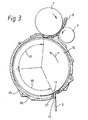
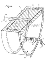
- guide members 37 (FIGS. 3 and 4) are provided in the region of the detachment section 19, preferably in the immediate vicinity of the outlet opening 17, and bil the detachment section 19 the end of the cover 15 attached or formed therein, for example, by milling and preferably consist of a wear-resistant material such as ceramic or plastic.
- the guide members 37 consist, for example, of webs which are arranged parallel to one another with their broad sides parallel to the fiber stream and otherwise in the direction of the axis of the opening roller 10.
- the longitudinal section of these webs is, for example, triangular in accordance with FIG. 4.
- the rear ends of the guide members 37 in the direction of flow of the fibers can border on the rear end of the detachment section 19, as shown in FIG. 3, so that in this case the outlet opening 17 is divided into a plurality of openings by the guide members 37, each of which passes a partial fiber stream.
- the number of webs and thus also the number of partial fiber streams can be selected differently. If the width of the combing zone 11 and the width of the opening roller 10 measured parallel / on its axis are considered to be a machine constant, the number of guide members 37 provided over the width of the combing zone 11 should be roughly inversely proportional to the pitch present in the individual case or to the needle spacing of the circular knitting - or circular knitting machine can be selected. In other words, it is expedient to always dimension the width of a partial fiber stream parallel to the axis of the opening roller 10 in such a way that, regardless of the division, not too many needle hooks 4 can be located in one and the same partial fiber stream at the same time.
- such a width of the partial fiber streams or such a lateral spacing of the guide members 37 from one another is particularly advantageous, in which or at the same time no more than one needle hook 4 can pass through a partial fiber stream.
- the number of guide members 37 thus corresponds approximately to the quotient of the width of the opening roller 10 and the needle pitch.
- FIGS. 5 to 7 show different embodiments for the design and arrangement of the guide members 37.
- the guide members 37 according to FIGS. 5 and 6 can have approximately the shape of an isosceles triangle with its base resting on the cover 15, the guide members are 37 in FIG. 7 in longitudinal section approximately like a right-angled triangle, the longer catheter of which is attached to a flap 38 and the shorter catheter of which forms the rear end of the guide member 37 in the direction of rotation.
- guide elements in the form of pins, disks, flexible elements or the like can be provided.
- the width of the guide members 37 measured in the axial direction of the opening roller 10 is not particularly critical, but should be chosen so that the formation of partial fiber streams is not hindered and an accumulation of fibers on the leading edges of the guide members 37 is prevented. For the same reason, it is also advisable to provide the guide members 37 with inclined surfaces 39 running in the flow direction from bottom to top (FIG. 5).
- the distance between the ends of the guide elements at the rear in the direction of flow from the needles 3 or the hooks 4 corresponding to dimension 40 in FIG. 6 can be selected differently and the greater the greater the staple length of the fibers used. If the size 40 is too large, however, there is a risk that the partial streams will reunite to form a total fiber stream before the needle hook 4 is reached, as a result of which the effect of the guide members 37 to avoid the incorporation of fibers into more than one stitch of the basic knitted fabric is lost.
- the absolute height of the guide elements 37 corresponding to the dimension 41 in FIG. 6 should be selected to be sufficiently large to allow the fibers 9 to pass through undisturbed.
- the guide members 37 only particularly clearly eliminate the effect of the transverse fibers if they completely cover the hooks 4 of the needles 3, ie if the dimension 42 is smaller than the hook length, because in this case all of them are in the opened hook 3 entering fibers must pass the spaces between the guide members 37.
- the measure 42 on the other hand larger than the H akenhow, ie, the hooks 4 are only partially covered by the guide members 37, the hooks 4, both fibers 9, which are supplied by the spaces between the guide members 37 can absorb and fibers 9 have migrated over the upper edges of the guide members 37.
- the proportion of those fibers which are incorporated into the basic knitted fabric or knitted fabric via more than one stitch can be controlled by changing the size 42.
- the guide members 37 are arranged on the pivotable flap 38, which is also part of the cover 15.
- the flap 38 is pivotally suspended from a pivot pin 43 at its end remote from the guide members 37 and can be pivoted in the direction of an arrow v such that the dimension 42 can be adjusted in any manner.
- the pivot pin 43 can protrude through an elongated hole 44 formed in the flap 38, which also enables the guide members 37 to be displaced in the direction of flow of the fibers (arrow w) and thus an adjustment of the dimension 40.
- the flap 38 including the guide members 37 is designed as an interchangeable unit, so that the shape and / or number and / or spacing of the guide members 37 can be changed in a few simple steps.
- control dimension 42 can be made, for example, to control dimension 42 according to a preselected pattern. To do this, it would be sufficient, for example, to move the flap 38 shown in FIG. 7 up and down in a pattern.
- mechanical or electromagnetic devices as are generally known for controlling other devices on circular knitting machines, are suitable as control devices.
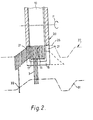
- FIGS. 6 and 7 differ on the one hand and FIGS. 6 and 7 on the other hand by the design of the detachment section 19. While the radial distance of the detachment section 19 from the lateral surface of the dissolving roller 10 according to FIG. 5 gradually increases in the direction of the outlet opening 17, 6 increases and then in the direction of the outlet opening 17 again, so that a kind of ski jump or ramp is formed directly in front of the outlet opening 17, through which the detached fibers are targeted in Rich device of the open hook 4 of the needles 3 are transported.
- the flap 38 according to FIG. 7 is designed, the radial distance from the lateral surface of the opening roller between the pivot pin 45 and the outlet opening 17 is constantly decreasing.
- the invention is not limited to the exemplary embodiments described, which can be modified in many ways.
- it can be provided to extend the cover 15 only to the outlet opening 17 and to provide a preferably pivotable flap 45 in the flow direction behind the combing zone 11, the part 46 of which faces the combing zone 11 is streamlined and arranged so that it divides the air and fiber flow behind the needles 3 into a main flow and a secondary flow, in order thereby to insert the fibers inserted into the needle hooks 4 into a wedge gap 47 between the flap 45 and the hooks 13 of the opening roller 10 to pull and thereby comb and orient, which increases the uniformity of the knitted fabric (Fig. 5 to 7).
- the drive 34 for the opening roller 10 is a drive motor which is independent of the knitting machine drive and which can also be operated when the circular knitting machine is at a standstill, so that the opening roller 10 has already reached the required high speed when the circular knitting machine is switched on and also maintains this until the circular knitting machine comes to a standstill again.
- a second, separate drive motor is not absolutely required, but it can be provided to ensure with the help of special gears and / or clutches that the circular knitting machine can only work when the opening roller 10 is running. Otherwise there would be areas in the knitted fabric at any standstill that have no fibers or unevenly distributed fibers.
- the required "high" speeds of the opening rollers were 4000 rpm for test machines with an opening roller diameter of 125 mm and with the other conditions being the same as when using the conventional opening devices.
Landscapes
- Engineering & Computer Science (AREA)
- Textile Engineering (AREA)
- Preliminary Treatment Of Fibers (AREA)
- Knitting Of Fabric (AREA)
- Knitting Machines (AREA)
Priority Applications (1)
| Application Number | Priority Date | Filing Date | Title |
|---|---|---|---|
| AT83102941T ATE35004T1 (de) | 1982-04-03 | 1983-03-24 | Rundstrick- oder rundwirkmaschine zur herstellung von strick- oder wirkwaren mit eingekaemmten fasern. |
Applications Claiming Priority (2)
| Application Number | Priority Date | Filing Date | Title |
|---|---|---|---|
| DE3212580 | 1982-04-03 | ||
| DE19823212580 DE3212580A1 (de) | 1982-04-03 | 1982-04-03 | Rundstrick- oder rundwirkmaschine zur herstellung von strick- oder wirkwaren mit eingekaemmten fasern |
Publications (3)
| Publication Number | Publication Date |
|---|---|
| EP0091025A2 true EP0091025A2 (fr) | 1983-10-12 |
| EP0091025A3 EP0091025A3 (en) | 1986-02-12 |
| EP0091025B1 EP0091025B1 (fr) | 1988-06-08 |
Family
ID=6160248
Family Applications (1)
| Application Number | Title | Priority Date | Filing Date |
|---|---|---|---|
| EP83102941A Expired EP0091025B1 (fr) | 1982-04-03 | 1983-03-24 | Métier à tricoter circulaire pour la fabrication d'articles tricotés comportant des fibres insérées |
Country Status (6)
| Country | Link |
|---|---|
| US (1) | US4546622A (fr) |
| EP (1) | EP0091025B1 (fr) |
| JP (1) | JPS58186645A (fr) |
| AT (1) | ATE35004T1 (fr) |
| DD (1) | DD210315A5 (fr) |
| DE (1) | DE3212580A1 (fr) |
Cited By (1)
| Publication number | Priority date | Publication date | Assignee | Title |
|---|---|---|---|---|
| EP0176809A1 (fr) * | 1984-09-13 | 1986-04-09 | Sulzer Morat GmbH | Métier à tricoter circulaire pour la fabrication d'articles tricotés à poils longs |
Families Citing this family (2)
| Publication number | Priority date | Publication date | Assignee | Title |
|---|---|---|---|---|
| DE3433642A1 (de) * | 1984-09-13 | 1986-03-20 | Sulzer Morat Gmbh, 7024 Filderstadt | Verfahren und rundstrickmaschine zur herstellung von strickwaren mit eingekaemmten fasern |
| JP4914426B2 (ja) * | 2008-11-26 | 2012-04-11 | 岡本株式会社 | 回転子を備えた編目編成具及び編機 |
Family Cites Families (20)
| Publication number | Priority date | Publication date | Assignee | Title |
|---|---|---|---|---|
| DE97374C (fr) * | ||||
| DE383362C (de) * | 1923-10-12 | Jowa Smith | Maschine zur Herstellung von Gewirken mit Faserdecke | |
| GB195802A (en) * | 1922-01-23 | 1923-04-12 | Iowa Smith | Improvements in and relating to the manufacture of pile knitted fabrics |
| US3014355A (en) * | 1958-04-07 | 1961-12-26 | Wildman Jacquard Co | Method and means for feeding fibers to a knitting machine |
| US3295337A (en) * | 1965-10-22 | 1967-01-03 | Amphenol Corp | Guard for carding mechanisms of knitting machines |
| FR1587056A (fr) * | 1968-05-03 | 1970-03-13 | ||
| US3755856A (en) * | 1971-04-23 | 1973-09-04 | Kimberly Clark Co | Method and apparatus for the formation of fiber fluff |
| CS167567B1 (fr) * | 1972-10-02 | 1976-04-29 | ||
| DE2253659A1 (de) * | 1972-11-02 | 1974-05-16 | Inst Textilmaschinen | Vielnadelmaschine, insbesondere naehwirkmaschine |
| US3896636A (en) * | 1972-11-06 | 1975-07-29 | Glenoit Mills | Sliver feeding means for high pile fabric circular knitting machines |
| GB1421748A (en) * | 1972-12-16 | 1976-01-21 | Wildeman A E Brunnschweiler D | Fleece knitted fabrics |
| US3968662A (en) * | 1973-08-31 | 1976-07-13 | M. Lowenstein & Sons, Inc. | Method of feeding fibers to a pile fabric circular knitting machine |
| US3999250A (en) * | 1973-10-10 | 1976-12-28 | The United States Of America As Represented By The Secretary Of Agriculture | Method of fiber distribution and ribbon forming |
| DE2430867A1 (de) * | 1974-06-27 | 1976-01-15 | Daniel Frishman | Verfahren und vorrichtung zur herstellung von florgewebe |
| US4187700A (en) * | 1977-11-03 | 1980-02-12 | Borg Textile Corporation | Latch guard and deep pile fabric circular knitting machine fitted therewith |
| DE2755380B2 (de) * | 1977-12-12 | 1981-01-08 | Temafa, Textilmaschinenfabrik Meissner, Morgner & Co Gmbh, 5060 Bergisch Gladbach | Vorrichtung zum öffnen und Reinigen von Baumwollabfällen |
| DE2925397C2 (de) * | 1979-06-23 | 1982-11-04 | Trützschler GmbH & Co KG, 4050 Mönchengladbach | Vorrichtung an einer Karde oder Krempel zur Bildung eines geteilten Faserflors |
| DE2932562C2 (de) * | 1979-08-10 | 1983-10-06 | Hollingsworth Gmbh, 7265 Neubulach | Auflösevorrichtung für Offenendspinnmaschinen |
| US4315347A (en) * | 1979-11-26 | 1982-02-16 | Kimberly-Clark Corporation | Fiberization of compressed fibrous sheets via Rando-Webber |
| DE3107714A1 (de) * | 1980-10-11 | 1982-06-24 | Sulzer Morat Gmbh, 7024 Filderstadt | Strick- oder wirkmaschine zur herstellung von florware mit eingekaemmten fasern |
-
1982
- 1982-04-03 DE DE19823212580 patent/DE3212580A1/de active Granted
-
1983
- 1983-03-14 US US06/475,389 patent/US4546622A/en not_active Expired - Fee Related
- 1983-03-24 EP EP83102941A patent/EP0091025B1/fr not_active Expired
- 1983-03-24 AT AT83102941T patent/ATE35004T1/de not_active IP Right Cessation
- 1983-03-31 DD DD83249419A patent/DD210315A5/de unknown
- 1983-04-01 JP JP58057752A patent/JPS58186645A/ja active Pending
Cited By (1)
| Publication number | Priority date | Publication date | Assignee | Title |
|---|---|---|---|---|
| EP0176809A1 (fr) * | 1984-09-13 | 1986-04-09 | Sulzer Morat GmbH | Métier à tricoter circulaire pour la fabrication d'articles tricotés à poils longs |
Also Published As
| Publication number | Publication date |
|---|---|
| ATE35004T1 (de) | 1988-06-15 |
| US4546622A (en) | 1985-10-15 |
| DE3212580C2 (fr) | 1989-12-07 |
| EP0091025B1 (fr) | 1988-06-08 |
| DE3212580A1 (de) | 1983-10-13 |
| DD210315A5 (de) | 1984-06-06 |
| JPS58186645A (ja) | 1983-10-31 |
| EP0091025A3 (en) | 1986-02-12 |
Similar Documents
| Publication | Publication Date | Title |
|---|---|---|
| DE2560526C2 (de) | Florfaser-Zubringereinrichtung | |
| DE1111549B (de) | Verfahren und Vorrichtung zum Verspinnen von Stapelfasern | |
| EP0779383B1 (fr) | Dispositiv de filature à bout libre | |
| EP0178466B1 (fr) | Procédé et dispositif pour la fabrication d'un fil | |
| DE2314666A1 (de) | Ringlose spinnmaschine | |
| DE3714212A1 (de) | Vorrichtung zum pneumatischen falschdrallspinnen mit einem streckwerk | |
| DE2138487C3 (de) | Vorrichtung zum Herstellen von Effektgarn mittels einer Offenend-Spinnvorrichtung | |
| DD222363A5 (de) | Fadenzufuhreinrichtung fuer strick- oder wirkmaschinen | |
| EP0175862A1 (fr) | Procédé et dispositif pour la production de fil | |
| EP0091025B1 (fr) | Métier à tricoter circulaire pour la fabrication d'articles tricotés comportant des fibres insérées | |
| DE3205938C2 (fr) | ||
| EP0049857B1 (fr) | Métier à tricoter circulaire pour fabriquer un tricot pelucheux ayant des fibres insérées | |
| CH694334A5 (de) | Vorrichtung zum Erzeugen eines Vlieses aus Faserflocken. | |
| DE2263904A1 (de) | Kardenbekleidung | |
| DE2953094A1 (de) | Offen-end-gesponnenes noppengarn sowie verfahren und vorrichtung zu seiner herstellung | |
| EP0620872B1 (fr) | Procede et dispositif a texturer des fils thermoplastiques | |
| DE3133280C2 (de) | Rundstrickmaschine zur Herstellung von Strickwaren mit eingekämmten Fasern | |
| CH620949A5 (en) | Apparatus for opening fibres on open-end spinning-rotor units. | |
| DE3521665A1 (de) | Friktionsspinnmittel fuer eine friktionsspinn-vorrichtung | |
| CH662134A5 (de) | Spinnvorrichtung. | |
| EP0176809B1 (fr) | Métier à tricoter circulaire pour la fabrication d'articles tricotés à poils longs | |
| DE2449311B2 (de) | Vorrichtung zum Zuführen eines Faserbandes an einer Offenendspinnmaschine | |
| DE3324001A1 (de) | Vorrichtung zum oe-friktionsspinnen | |
| CH675434A5 (fr) | ||
| DE68905270T2 (de) | Kettfaden-einziehduese. |
Legal Events
| Date | Code | Title | Description |
|---|---|---|---|
| PUAI | Public reference made under article 153(3) epc to a published international application that has entered the european phase |
Free format text: ORIGINAL CODE: 0009012 |
|
| AK | Designated contracting states |
Designated state(s): AT FR GB IT |
|
| PUAL | Search report despatched |
Free format text: ORIGINAL CODE: 0009013 |
|
| AK | Designated contracting states |
Designated state(s): AT FR GB IT |
|
| 17P | Request for examination filed |
Effective date: 19860802 |
|
| 17Q | First examination report despatched |
Effective date: 19871016 |
|
| ITF | It: translation for a ep patent filed | ||
| GRAA | (expected) grant |
Free format text: ORIGINAL CODE: 0009210 |
|
| AK | Designated contracting states |
Kind code of ref document: B1 Designated state(s): AT FR GB IT |
|
| REF | Corresponds to: |
Ref document number: 35004 Country of ref document: AT Date of ref document: 19880615 Kind code of ref document: T |
|
| GBT | Gb: translation of ep patent filed (gb section 77(6)(a)/1977) | ||
| ET | Fr: translation filed | ||
| PG25 | Lapsed in a contracting state [announced via postgrant information from national office to epo] |
Ref country code: AT Effective date: 19890324 |
|
| PGFP | Annual fee paid to national office [announced via postgrant information from national office to epo] |
Ref country code: GB Payment date: 19890331 Year of fee payment: 7 |
|
| PLBE | No opposition filed within time limit |
Free format text: ORIGINAL CODE: 0009261 |
|
| STAA | Information on the status of an ep patent application or granted ep patent |
Free format text: STATUS: NO OPPOSITION FILED WITHIN TIME LIMIT |
|
| 26N | No opposition filed | ||
| PG25 | Lapsed in a contracting state [announced via postgrant information from national office to epo] |
Ref country code: FR Free format text: LAPSE BECAUSE OF NON-PAYMENT OF DUE FEES Effective date: 19891130 |
|
| REG | Reference to a national code |
Ref country code: FR Ref legal event code: ST |
|
| PG25 | Lapsed in a contracting state [announced via postgrant information from national office to epo] |
Ref country code: GB Effective date: 19900324 |
|
| GBPC | Gb: european patent ceased through non-payment of renewal fee | ||
| ITTA | It: last paid annual fee |