EP0091774B1 - Numerische Steuerung - Google Patents
Numerische Steuerung Download PDFInfo
- Publication number
- EP0091774B1 EP0091774B1 EP83301918A EP83301918A EP0091774B1 EP 0091774 B1 EP0091774 B1 EP 0091774B1 EP 83301918 A EP83301918 A EP 83301918A EP 83301918 A EP83301918 A EP 83301918A EP 0091774 B1 EP0091774 B1 EP 0091774B1
- Authority
- EP
- European Patent Office
- Prior art keywords
- code
- code data
- numerical control
- item
- data
- Prior art date
- Legal status (The legal status is an assumption and is not a legal conclusion. Google has not performed a legal analysis and makes no representation as to the accuracy of the status listed.)
- Expired
Links
Images

Classifications
-
- G—PHYSICS
- G05—CONTROLLING; REGULATING
- G05B—CONTROL OR REGULATING SYSTEMS IN GENERAL; FUNCTIONAL ELEMENTS OF SUCH SYSTEMS; MONITORING OR TESTING ARRANGEMENTS FOR SUCH SYSTEMS OR ELEMENTS
- G05B19/00—Program-control systems
- G05B19/02—Program-control systems electric
- G05B19/18—Numerical control [NC], i.e. automatically operating machines, in particular machine tools, e.g. in a manufacturing environment, so as to execute positioning, movement or co-ordinated operations by means of program data in numerical form
- G05B19/408—Numerical control [NC], i.e. automatically operating machines, in particular machine tools, e.g. in a manufacturing environment, so as to execute positioning, movement or co-ordinated operations by means of program data in numerical form characterised by data handling or data format, e.g. reading, buffering or conversion of data
-
- G—PHYSICS
- G05—CONTROLLING; REGULATING
- G05B—CONTROL OR REGULATING SYSTEMS IN GENERAL; FUNCTIONAL ELEMENTS OF SUCH SYSTEMS; MONITORING OR TESTING ARRANGEMENTS FOR SUCH SYSTEMS OR ELEMENTS
- G05B2219/00—Program-control systems
- G05B2219/30—Nc systems
- G05B2219/35—Nc in input of data, input till input file format
- G05B2219/35245—Expansion of control words, code of standard language to increase functionality
-
- G—PHYSICS
- G05—CONTROLLING; REGULATING
- G05B—CONTROL OR REGULATING SYSTEMS IN GENERAL; FUNCTIONAL ELEMENTS OF SUCH SYSTEMS; MONITORING OR TESTING ARRANGEMENTS FOR SUCH SYSTEMS OR ELEMENTS
- G05B2219/00—Program-control systems
- G05B2219/30—Nc systems
- G05B2219/35—Nc in input of data, input till input file format
- G05B2219/35252—Function, machine codes G, M
Definitions
- This invention relates to a numerical control.
- a numerical control device referred to as an NC device, is adapted to read numerical control data such as positional data, M-code data and G-code data from a tape or internal memory sequentially in block-by-block fashion, and to execute processing based on the numerical control data so as to control a machine tool.
- the G-code data mentioned above specifies the control function of the NC device and is expressed by the letter of the alphabet G and a two-digit numerical value following the letter G.
- the NC device When an item of G-code data is commanded, the NC device performs preparatory and processing operations to perform the control function indicated by that item of G-code data.
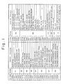
- Fig. 1 is a table showing the correspondence between various items of conventional G-code data and control functions. Items of related G-code data are grouped as follows: (a) G00 to G03; (b) G17 to G19; (c) G20, G21; (d) G22, G23; (e) G40 to G42; (f) G43, G44, G49; (g) G73 to G89; (h) G90, G91; (i) G94, G95; and (j) G98, G99.
- Each of the items of G-code data in the same group constitutes so-called modal information with the other items in that group.
- an item of G-code data is commanded by being expressed as the letter G and a numerical value following G.
- conventional practice is to establish a corresponding G code of a number larger than the other G codes, namely to increase the numerical value which follows the letter G.
- a disadvantage with this method is that it becomes quite difficult to store the correspondence between the items of G-code data and the G-code data control functions as the G codes grow large in quantity, and the programmer is compelled to refer repeatedly to a correspondence table, making programming a troublesome and time-consuming task.
- a numerical control method for a numerical control device which executes numerical control processing based on a machining program composed of multiple items of numerical control command data such as numerical command data and G-code data which are stored in a machining program memory in blocks, characterised in that the method has the steps of:
- a numerical control device for executing numerical control processing based on a machining program composed of multiple items of numerical control command data including G-code data, comprising:
- the present invention can provide numerical control facilities through which additional items of G-code data can be provided in a simple manner.
- the present invention can provide numerical control facilities which enable a programmer readily to store the correspondence between G-code data and control functions.
- the present invention can provide numerical control facilities through which items of G-code data which mutually constitute modal information can be gathered into the same group without necessitating a change in the corresponding relationship between G-code data and their control functions, even when there is a large quantity of G-code data used for commanding related or similar control functions, or when there is a need for additional items of G-code data.
- the present invention provides numerical control facilities capable of simplifying processing for renewing the contents of a G-code memory by establishing correspondence between the numerical value following the letter G and an address of the G-code memory, and between a numerical value or letter of the alphabet, which follows a period or like symbol, and a bit position at said address.
- numerical control facilities for a numerical control device which executes processing based on a machining program composed of multiple items of numerical control command data such as numerical command data and G-code data.
- Each item of G-code data is expressed in the form of an alphabetic character or letter G, a numerical value following G, and a code following the numerical value.
- the items of G-code data are inserted in a machining program at suitable locations, for subsequent reading by a machining program and execution of the numerical control processing prescribed.
- the G-code data in the machining program is discriminated when the program is read, and the numerical control device caused to execute processing specified by the numerical value following the character G and the code following the numerical value of each item of discriminated G-code data.
- Items of G-code data are arranged in a plurality of groups, in which items belonging to the same group have identical numerical values following the character G.
- an item of G-code data is represented by the alphabetic character (letter) G, a numerical value following the character G, and a code which follows the numerical value.
- an item of G-code data is composed of the character G, a two-digit numerical value following G, a period symbol following the two-digit numerical value, and a one-digit numerical value following the period.
- an item of G-code data may consist of the character G, a two-digit numerical value, a colon (or a comma) symbol, and an alphabetic character, each following the other in the stated order.
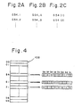
- Fig. 2A an item of G-code data is composed of the character G, a two-digit numerical value following G, a period symbol following the two-digit numerical value, and a one-digit numerical value following the period.
- an item of G-code data may consist of the character G, a two-digit numerical value, a colon (or a comma) symbol, and an alphabetic character, each following the other in the stated order.
- the item of G-code data may be represented by the character G, the two-digit numerical value following G, and a one-digit numerical value, which is enclosed in parentheses, following the two-digit numerical value.
- the period, colon (or comma) and parentheses serve as examples of symbols only are not the only symbols capable of being used to form the code attached to the two-digit numerical value.
- an item of G-code data according to the invention can be created by attaching a code comprising a combination of any symbol, such as a period, colon (or comma), 'parentheses, semicolon or slash mark, and a numerical value or alphabetic character.
- the numerical value following the character G may comprise a single digit, rather than the two digits in the illustrated example.
- the device includes an operator's panel 101 having a mode selection switch and start button, which are not shown.
- a processor 102 which is under the control of a control program stored in a ROM 103, causes a tape reader 104 to read in NC data in block-by-block fashion from an NC tape 105.
- the processor 102 proceeds to read the NC data and store the same in a working memory 106, and then decodes the data in accordance with the control program to execute the numerical control processing prescribed by the data.
- an item of the NC data is an M-function instruction, S-function instruction or T-function instruction
- a signal indicative of the instruction is delivered to a machine tool 201 through a power magnetics unit 107.
- an item of NC data read in from the NC tape 105 is a G-code
- the item of G-code data is planted in a G-code memory 108.
- one bit of store is allotted to one item of G-code data.
- the bit corresponding thereto goes to logical "1"; bits corresponding to other items of G-code data, which are modals with respect to said commanded item of G-code data, go to logical "0".
- Fig. 4 illustrating the manner in which G-code data is stored in the G-code memory 108.
- the latter has storage areas located at addresses 00 through 99, each address location comprising, say, eight bits b, through b a .
- an item of G-code data is expressed in terms of the character G, a two-digit number following G, and a code following the two-digit number, the code comprising a period and a numerical value which follows the period, as shown in Fig. 2A.
- correspondence is established between the two-digit number and an address of the G-code memory 108, and between the numerical value following the period and a bit position at said address.
- G functions which are modals with respect to one another, are designated by G54.1, G54.2, G54.3 and G54.4, respectively: positioning in rapid traverse mode, linear interpolation in cutting feed mode, clockwise circular interpolation, and counterclockwise circular interpolation.
- G54.1 is the command read in from the NC tape 105
- G54.2, G54.3 and G54.4 are the commands, it will suffice to store 00000010, 00000100 and 00001000 at address 54 of the G-code memory 108, respectively. This facilitates greatly the processing for writing the contents of memory 108 anew.
- G61.1 and G61.2 are items of G-code data that are modals with respect to each other.
- G61.1 indicates that an item of positional data is being commanded in the form of an absolute value
- G61.2 indicates that it is being commanded in the form of an incremental value.
- code data G71.1, G71.2 and G71.3 are items of G-code data that are modals with respect to each other.
- G71.1 indicates cancellation of cutter offset (tool diameter)
- G71.2 is G-code data indicating that tool path is to be offset by a predetermined offset quantity to the left side of the direction of tool advance
- G73.3 is G-code data indicating that tool path is to be offset by a predetermined offset quantity to the right side of the direction of tool advance.
- the offset quantity is specified by entering, from the NC tape 105, either the item of G-code data G71.2 or G71.3, together with an alphabetic character D and a two-digit numerical value following D.
- the offset quantity is read out of an offset memory 109 from an address designated by the two-digit numerical value which follows the character D.
- the processor 102 When an item of NC data read in from the NC tape 105 is path data, the processor 102 first examines the contents of the G-code memory 108 to determine which item of G-code data was the last commanded in each group related to path control. For example, assume that "00000010", “00000001” and “00000010” are the items of data located at addresses 54, 61 and 71, respectively, of the G-code memory 108, as shown in Fig. 4. In other words, among the groups related to path control, assume that the items of G-code data commanded most recently were G54.2 (linear interpolation in cutting feed mode), G61.1 (absolute programming), and G71.2 (cutter offset left), respectively.
- the processor 102 Under these conditions the processor 102, according to the control program, will execute processing for cutter offset, creation of incremental values and linear interpolation, corresponding to the foregoing items of G-code data. The process steps will be described later with reference to Fig. 5.
- the foregoing processing provides X- and Y-axis amounts of movement ⁇ X, ⁇ Y to be traversed by the tool over a minute length of time ⁇ T, the processor 102 applying signals indicative of ⁇ X and ⁇ Y to a pulse distributor 110, shown in Fig. 3. Values of ⁇ X and ⁇ Y are successively found and applied to the pulse distributor 110 by the processor 102 at intervals of AT until the tool (or any object being controlled) arrives as the commanded position.
- the pulse distributor 110 in response to the ⁇ X, ⁇ Y inputs thereto, performs a linear interpolation operation simultaneously along the two axes (X and Y axes), producing distributed pulses Px, Py that are applied to X-axis and Y-axis servo units 111X, 111Y, respectively. These respond by driving respective servomotors 201X, 201Y into rotation, thereby transporting the tool.
- numeral 112 denotes a manual data input unit for setting offset quantities and for modifying NC data.
- ADB denotes an address bus, DTB a data bus, and CTB a control bus.
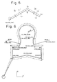
- Fig. 5 for describing processing executed by the processor 102 when the commanded items of G-code data are G54.2 (linear interpolation, G61.1 (absolute programming) and G71.2 (cutter offset left).
- the programmed path in Fig. 5 is composed of two straight lines L1, L2, which intersect at an angle a greater than 90° but less than 180°.
- the processor 102 pre-reads a move command located in the present block b, and a move command located in the next block b 2 , derives straight lines L1', L2' obtained by applying a specified offset quantity r, to the straight lines L1, L2 in the present block b 1 and next block b 2 , respectively, and computer the coordinates of the point S1 at which L1' and L2' intersect, these then being stored in the working memory 106.
- the processor 102 finds the X-and Y-axis components Xi, Yi of a line segment SoS1 extending from an end point So in the previous block to the end point S1 in the present block. Note that the coordinates XA, YA of the point So are the coordinates of the current position of the tool and have been stored in the working memory 106 by previous processing.
- the processor 102 Upon finding the X- and Y-axis components Xi, Yi, the processor 102 stores them in the working memory 106 as remaining amounts of movement XR, YR, respectively, and performs the following operations to compute the X- and Y-axis amounts of movement ⁇ X, ⁇ Y to be traversed during the predetermined time ⁇ T:
- ⁇ X and ⁇ Y are stored in a storage area of the working memory 106 and are fed into the pulse distributor 110.
- AT in the foregoing equations is a preset quantity.
- Fx, Fy are the feed speeds along the X and Y axes, respectively, and are decided by the following equations in which F is the commanded feed speed:
- the pulse distributor 110 Upon receiving the ⁇ X, ⁇ Y inputs, the pulse distributor 110 executes a linear interpolation simultaneously along the X and Y axes. With each lapse of the time ⁇ T, the processor 102 computes values of ⁇ X, ⁇ Y anew and accumulates the resulting values along the respective axes. In other words, the processor 102 executes the operations given by: to update the coordinates XA, XY of the current position, which coordinates are then stored in the working memory 106. The processor also performs the following operations with each lapse of the time ⁇ T: to update the remaining amounts of movement stored in the working memory 106.
- Fig. 6 is a diagram useful in describing the path followed by a tool in accordance with the method of the present invention.
- the solid line indicates the programmed path, and the broken line the path that is actually followed by the tool.
- An example of the machining program is as follows:
- the G codes can be formed into groups without altering the correspondence already between G codes and their associated functions.
- processing for writing anew the contents of the G-code memory 108 is greatly simplified owing to the correspondence established between the numerical value following the character G and an address of the G-code memory 108, as well as between the numerical value or alphabetic character in the code following the first-mentioned numerical value, and a bit position at said address.
Landscapes
- Engineering & Computer Science (AREA)
- Human Computer Interaction (AREA)
- Manufacturing & Machinery (AREA)
- Physics & Mathematics (AREA)
- General Physics & Mathematics (AREA)
- Automation & Control Theory (AREA)
- Numerical Control (AREA)
Claims (9)
dadurch gekennzeichnet, daß das Verfahren Schritte aufweist zum
Applications Claiming Priority (2)
| Application Number | Priority Date | Filing Date | Title |
|---|---|---|---|
| JP57714/82 | 1982-04-07 | ||
| JP57057714A JPS58175003A (ja) | 1982-04-07 | 1982-04-07 | 数値制御指令方式 |
Publications (2)
| Publication Number | Publication Date |
|---|---|
| EP0091774A1 EP0091774A1 (de) | 1983-10-19 |
| EP0091774B1 true EP0091774B1 (de) | 1988-06-08 |
Family
ID=13063611
Family Applications (1)
| Application Number | Title | Priority Date | Filing Date |
|---|---|---|---|
| EP83301918A Expired EP0091774B1 (de) | 1982-04-07 | 1983-04-06 | Numerische Steuerung |
Country Status (4)
| Country | Link |
|---|---|
| US (1) | US4591968A (de) |
| EP (1) | EP0091774B1 (de) |
| JP (1) | JPS58175003A (de) |
| DE (1) | DE3377025D1 (de) |
Families Citing this family (36)
| Publication number | Priority date | Publication date | Assignee | Title |
|---|---|---|---|---|
| JPS5969873A (ja) * | 1982-10-15 | 1984-04-20 | Fanuc Ltd | デ−タ入出力装置 |
| JPS59174916A (ja) * | 1983-03-25 | 1984-10-03 | Mitsubishi Electric Corp | 数値制御装置 |
| KR890001314B1 (en) * | 1983-05-23 | 1989-04-29 | Mitsubishi Electric Corp | Numbering control apparatus |
| JPS60157608A (ja) * | 1984-01-26 | 1985-08-17 | Fanuc Ltd | 数値制御方式 |
| JPS60229111A (ja) * | 1984-04-26 | 1985-11-14 | Fanuc Ltd | 数値制御方式 |
| JP2701022B2 (ja) * | 1984-05-22 | 1998-01-21 | ファナック 株式会社 | プログラマブルミラーイメージ機能を有する数値制御装置 |
| JPS6225302A (ja) * | 1985-07-25 | 1987-02-03 | Fanuc Ltd | 数値制御装置 |
| JPS62267804A (ja) * | 1986-05-15 | 1987-11-20 | Fanuc Ltd | Ncデ−タ変更方法 |
| JPS63181005A (ja) * | 1987-01-23 | 1988-07-26 | Fanuc Ltd | 数値制御装置の並列処理方式 |
| DE3706275A1 (de) * | 1987-02-26 | 1988-09-08 | Mitsubishi Electric Corp | Numerische steuervorrichtung |
| JPS6462706A (en) * | 1987-09-03 | 1989-03-09 | Fanuc Ltd | Nc program output system |
| JPS6468810A (en) * | 1987-09-10 | 1989-03-14 | Fanuc Ltd | High speed working system |
| US4914364A (en) * | 1987-10-22 | 1990-04-03 | Mitsubishi Denki Kabushiki Kaisha | Numerical control apparatus |
| JPH01152507A (ja) * | 1987-12-09 | 1989-06-15 | Fanuc Ltd | Ncプログラム登録方式 |
| US4868469A (en) * | 1988-05-16 | 1989-09-19 | Advanced Micro Devices, Inc. | Multi-way polling, branching and waiting opcode |
| JPH0236404A (ja) * | 1988-07-26 | 1990-02-06 | Fanuc Ltd | Nc指令方式 |
| JPH02110708A (ja) * | 1988-10-20 | 1990-04-23 | Fanuc Ltd | 主軸制御方式 |
| JPH02302803A (ja) * | 1989-05-18 | 1990-12-14 | Fanuc Ltd | ピッチ誤差補正データの書き換え方式 |
| JP2982010B2 (ja) * | 1989-06-23 | 1999-11-22 | 三菱電機株式会社 | 数値制御方法及び装置 |
| JP2639169B2 (ja) * | 1990-04-09 | 1997-08-06 | 三菱電機株式会社 | 数値制御装置 |
| JP2718260B2 (ja) * | 1990-11-08 | 1998-02-25 | 三菱電機株式会社 | 数値制御装置 |
| US5682319A (en) * | 1991-06-04 | 1997-10-28 | Anca Pty. Ltd. | Computer numerically controlled machines |
| US5223777A (en) * | 1992-04-06 | 1993-06-29 | Allen-Bradley Company, Inc. | Numerical control system for irregular pocket milling |
| KR0161010B1 (ko) * | 1992-09-18 | 1999-01-15 | 윤종용 | 공구직경에 따른 이동경로 보정방법 |
| JP3449789B2 (ja) * | 1994-07-14 | 2003-09-22 | 松下電器産業株式会社 | 部品実装方法 |
| KR0160672B1 (ko) * | 1995-02-13 | 1999-03-20 | 김광호 | 미러 이미지 제어를 위한 수치 제어 방법 및 장치 |
| US5691897A (en) * | 1995-05-30 | 1997-11-25 | Roy-G-Biv Corporation | Motion control systems |
| US20100131081A1 (en) * | 1995-05-30 | 2010-05-27 | Brown David W | Systems and methods for motion control |
| US6317646B1 (en) | 1997-03-19 | 2001-11-13 | Fadal Machining Centers, Inc. | CNC machine having interactive control of corner tolerance that is programmed to vary with the corner angle |
| JPH11345009A (ja) * | 1998-06-02 | 1999-12-14 | Fanuc Ltd | 数値制御装置 |
| JP2002172543A (ja) * | 2000-09-29 | 2002-06-18 | Toyoda Mach Works Ltd | 加工装置の制御パラメータ設定装置及び制御パラメータ設定方法 |
| US20100131077A1 (en) * | 2004-02-25 | 2010-05-27 | Brown David W | Data Collection Systems and Methods for Motion Control |
| US7333032B1 (en) * | 2006-01-20 | 2008-02-19 | Calypto Design Systems, Inc. | System, method and computer program product for word-level computations and storage |
| JP4972447B2 (ja) * | 2007-04-06 | 2012-07-11 | オークマ株式会社 | 数値制御装置 |
| JP5280665B2 (ja) * | 2007-10-26 | 2013-09-04 | オークマ株式会社 | 手動シフト操作機能を備えた数値制御装置 |
| WO2018020663A1 (ja) * | 2016-07-29 | 2018-02-01 | 三菱電機株式会社 | 数値制御装置 |
Family Cites Families (9)
| Publication number | Priority date | Publication date | Assignee | Title |
|---|---|---|---|---|
| US3616993A (en) * | 1968-12-04 | 1971-11-02 | Logic Systems Inc | Numerical control system |
| US3866179A (en) * | 1972-09-22 | 1975-02-11 | Giddings & Lewis | Numerical control with envelope offset and automatic path segment transitions |
| NL7511705A (nl) * | 1975-10-06 | 1977-04-12 | Philips Nv | Numerieke besturing voor een multigereedschap- machine. |
| JPS521288A (en) * | 1975-06-24 | 1977-01-07 | Oki Electric Ind Co Ltd | Numeric value control system having performance to call program |
| JPS54117883A (en) * | 1978-03-06 | 1979-09-12 | Okuma Mach Works Ltd | Numerical control device |
| JPS56168223A (en) * | 1980-05-28 | 1981-12-24 | Fanuc Ltd | Numerical value control system |
| JPS5731003A (en) * | 1980-08-01 | 1982-02-19 | Fanuc Ltd | Numerical control system |
| US4328448A (en) * | 1980-09-02 | 1982-05-04 | Cincinnati Milacron Inc. | Method for programmably controlling the sequence of execution of data blocks in a program |
| JPS57102733A (en) * | 1980-12-16 | 1982-06-25 | Toyoda Mach Works Ltd | Automatic dimension correcting apparatus for spare tool |
-
1982
- 1982-04-07 JP JP57057714A patent/JPS58175003A/ja active Pending
-
1983
- 1983-04-01 US US06/481,249 patent/US4591968A/en not_active Expired - Lifetime
- 1983-04-06 EP EP83301918A patent/EP0091774B1/de not_active Expired
- 1983-04-06 DE DE8383301918T patent/DE3377025D1/de not_active Expired
Also Published As
| Publication number | Publication date |
|---|---|
| US4591968A (en) | 1986-05-27 |
| EP0091774A1 (de) | 1983-10-19 |
| JPS58175003A (ja) | 1983-10-14 |
| DE3377025D1 (en) | 1988-07-14 |
Similar Documents
| Publication | Publication Date | Title |
|---|---|---|
| EP0091774B1 (de) | Numerische Steuerung | |
| US4587608A (en) | Method of automatically creating numerical control data in one of a plurality of data formats | |
| US4445182A (en) | Method of control of NC machine tools | |
| US4503507A (en) | Robot control data processing apparatus | |
| CA1149045A (en) | Numerically controlled machine tool | |
| KR850000328B1 (ko) | 수치 제어방법 | |
| US4890234A (en) | NC data modification method | |
| GB2094025A (en) | Method and apparatus for robot control | |
| EP0223857B1 (de) | Kompilierungsverfahren von numerisch gesteuerten programmen für eine vier-achsen-drehbank | |
| US4606001A (en) | Customized canned cycles for computer numerical control system | |
| US4404506A (en) | Tool position offsetting system for a spare tool | |
| EP0127122B1 (de) | Numerisches Steuersystem mit einer Anzeige-Einheit und vom System gesteuerte Werkzeugmaschine | |
| EP0103428B1 (de) | Programmiergerät für eine numerische Steuerung | |
| EP0148273B1 (de) | Numerische steuervorrichtung | |
| EP0230471B1 (de) | Handbedienungssystem für durch eine numerisch gesteuerte einheit gesteuerte maschine | |
| US4608644A (en) | Tool life, offset, and selection supervision method | |
| US4782438A (en) | Means and method for translating a turret punch press control program into a laser beam machine control program | |
| EP0079388B1 (de) | Numerisches steuerverfahren | |
| GB2062293A (en) | Method of control of NC machine tools | |
| EP0060039B1 (de) | System zur numerischen Steuerung von Werkzeugmaschinen | |
| EP0074412B1 (de) | Numerische steuereinheit | |
| US4924403A (en) | Numerical control method and system therefor having override playback function | |
| GB2043957A (en) | Numerical Control System | |
| EP0364600B1 (de) | Rundgewinde-bearbeitungsmethode | |
| EP0099733B1 (de) | Verfahren und Einrichtung zur Herstellung von NS-Programmen |
Legal Events
| Date | Code | Title | Description |
|---|---|---|---|
| PUAI | Public reference made under article 153(3) epc to a published international application that has entered the european phase |
Free format text: ORIGINAL CODE: 0009012 |
|
| AK | Designated contracting states |
Designated state(s): DE FR GB |
|
| 17P | Request for examination filed |
Effective date: 19840406 |
|
| 17Q | First examination report despatched |
Effective date: 19860408 |
|
| R17C | First examination report despatched (corrected) |
Effective date: 19870305 |
|
| GRAA | (expected) grant |
Free format text: ORIGINAL CODE: 0009210 |
|
| AK | Designated contracting states |
Kind code of ref document: B1 Designated state(s): DE FR GB |
|
| REF | Corresponds to: |
Ref document number: 3377025 Country of ref document: DE Date of ref document: 19880714 |
|
| ET | Fr: translation filed | ||
| PLBE | No opposition filed within time limit |
Free format text: ORIGINAL CODE: 0009261 |
|
| STAA | Information on the status of an ep patent application or granted ep patent |
Free format text: STATUS: NO OPPOSITION FILED WITHIN TIME LIMIT |
|
| 26N | No opposition filed | ||
| PGFP | Annual fee paid to national office [announced via postgrant information from national office to epo] |
Ref country code: FR Payment date: 19910322 Year of fee payment: 9 |
|
| PG25 | Lapsed in a contracting state [announced via postgrant information from national office to epo] |
Ref country code: FR Effective date: 19921230 |
|
| REG | Reference to a national code |
Ref country code: FR Ref legal event code: ST |
|
| PGFP | Annual fee paid to national office [announced via postgrant information from national office to epo] |
Ref country code: GB Payment date: 19930326 Year of fee payment: 11 |
|
| PG25 | Lapsed in a contracting state [announced via postgrant information from national office to epo] |
Ref country code: GB Effective date: 19940406 |
|
| GBPC | Gb: european patent ceased through non-payment of renewal fee |
Effective date: 19940406 |
|
| PGFP | Annual fee paid to national office [announced via postgrant information from national office to epo] |
Ref country code: DE Payment date: 20020410 Year of fee payment: 20 |