EP0091850A1 - Automatischer Flüssigkeitsniveauregulator für superfluides Helium in einem Behälter - Google Patents
Automatischer Flüssigkeitsniveauregulator für superfluides Helium in einem Behälter Download PDFInfo
- Publication number
- EP0091850A1 EP0091850A1 EP83400630A EP83400630A EP0091850A1 EP 0091850 A1 EP0091850 A1 EP 0091850A1 EP 83400630 A EP83400630 A EP 83400630A EP 83400630 A EP83400630 A EP 83400630A EP 0091850 A1 EP0091850 A1 EP 0091850A1
- Authority
- EP
- European Patent Office
- Prior art keywords
- helium
- tank
- level
- reservoir
- superfluid
- Prior art date
- Legal status (The legal status is an assumption and is not a legal conclusion. Google has not performed a legal analysis and makes no representation as to the accuracy of the status listed.)
- Granted
Links
Images
Classifications
-
- G—PHYSICS
- G01—MEASURING; TESTING
- G01F—MEASURING VOLUME, VOLUME FLOW, MASS FLOW OR LIQUID LEVEL; METERING BY VOLUME
- G01F23/00—Indicating or measuring liquid level or level of fluent solid material, e.g. indicating in terms of volume or indicating by means of an alarm
- G01F23/14—Indicating or measuring liquid level or level of fluent solid material, e.g. indicating in terms of volume or indicating by means of an alarm by measurement of pressure
- G01F23/16—Indicating, recording, or alarm devices being actuated by mechanical or fluid means, e.g. using gas, mercury, or a diaphragm as transmitting element, or by a column of liquid
- G01F23/162—Indicating, recording, or alarm devices being actuated by mechanical or fluid means, e.g. using gas, mercury, or a diaphragm as transmitting element, or by a column of liquid by a liquid column
-
- F—MECHANICAL ENGINEERING; LIGHTING; HEATING; WEAPONS; BLASTING
- F17—STORING OR DISTRIBUTING GASES OR LIQUIDS
- F17C—VESSELS FOR CONTAINING OR STORING COMPRESSED, LIQUEFIED OR SOLIDIFIED GASES; FIXED-CAPACITY GAS-HOLDERS; FILLING VESSELS WITH, OR DISCHARGING FROM VESSELS, COMPRESSED, LIQUEFIED, OR SOLIDIFIED GASES
- F17C13/00—Details of vessels or of the filling or discharging of vessels
- F17C13/02—Special adaptations of indicating, measuring, or monitoring equipment
- F17C13/021—Special adaptations of indicating, measuring, or monitoring equipment having the height as the parameter
-
- G—PHYSICS
- G01—MEASURING; TESTING
- G01F—MEASURING VOLUME, VOLUME FLOW, MASS FLOW OR LIQUID LEVEL; METERING BY VOLUME
- G01F23/00—Indicating or measuring liquid level or level of fluent solid material, e.g. indicating in terms of volume or indicating by means of an alarm
-
- F—MECHANICAL ENGINEERING; LIGHTING; HEATING; WEAPONS; BLASTING
- F17—STORING OR DISTRIBUTING GASES OR LIQUIDS
- F17C—VESSELS FOR CONTAINING OR STORING COMPRESSED, LIQUEFIED OR SOLIDIFIED GASES; FIXED-CAPACITY GAS-HOLDERS; FILLING VESSELS WITH, OR DISCHARGING FROM VESSELS, COMPRESSED, LIQUEFIED, OR SOLIDIFIED GASES
- F17C2205/00—Vessel construction, in particular mounting arrangements, attachments or identifications means
- F17C2205/03—Fluid connections, filters, valves, closure means or other attachments
- F17C2205/0302—Fittings, valves, filters, or components in connection with the gas storage device
- F17C2205/0323—Valves
-
- F—MECHANICAL ENGINEERING; LIGHTING; HEATING; WEAPONS; BLASTING
- F17—STORING OR DISTRIBUTING GASES OR LIQUIDS
- F17C—VESSELS FOR CONTAINING OR STORING COMPRESSED, LIQUEFIED OR SOLIDIFIED GASES; FIXED-CAPACITY GAS-HOLDERS; FILLING VESSELS WITH, OR DISCHARGING FROM VESSELS, COMPRESSED, LIQUEFIED, OR SOLIDIFIED GASES
- F17C2221/00—Handled fluid, in particular type of fluid
- F17C2221/01—Pure fluids
- F17C2221/016—Noble gases (Ar, Kr, Xe)
- F17C2221/017—Helium
-
- F—MECHANICAL ENGINEERING; LIGHTING; HEATING; WEAPONS; BLASTING
- F17—STORING OR DISTRIBUTING GASES OR LIQUIDS
- F17C—VESSELS FOR CONTAINING OR STORING COMPRESSED, LIQUEFIED OR SOLIDIFIED GASES; FIXED-CAPACITY GAS-HOLDERS; FILLING VESSELS WITH, OR DISCHARGING FROM VESSELS, COMPRESSED, LIQUEFIED, OR SOLIDIFIED GASES
- F17C2223/00—Handled fluid before transfer, i.e. state of fluid when stored in the vessel or before transfer from the vessel
- F17C2223/01—Handled fluid before transfer, i.e. state of fluid when stored in the vessel or before transfer from the vessel characterised by the phase
- F17C2223/0146—Two-phase
- F17C2223/0153—Liquefied gas, e.g. LPG, GPL
- F17C2223/0161—Liquefied gas, e.g. LPG, GPL cryogenic, e.g. LNG, GNL, PLNG
-
- F—MECHANICAL ENGINEERING; LIGHTING; HEATING; WEAPONS; BLASTING
- F17—STORING OR DISTRIBUTING GASES OR LIQUIDS
- F17C—VESSELS FOR CONTAINING OR STORING COMPRESSED, LIQUEFIED OR SOLIDIFIED GASES; FIXED-CAPACITY GAS-HOLDERS; FILLING VESSELS WITH, OR DISCHARGING FROM VESSELS, COMPRESSED, LIQUEFIED, OR SOLIDIFIED GASES
- F17C2250/00—Accessories; Control means; Indicating, measuring or monitoring of parameters
- F17C2250/06—Controlling or regulating of parameters as output values
- F17C2250/0605—Parameters
- F17C2250/061—Level of content in the vessel
-
- Y—GENERAL TAGGING OF NEW TECHNOLOGICAL DEVELOPMENTS; GENERAL TAGGING OF CROSS-SECTIONAL TECHNOLOGIES SPANNING OVER SEVERAL SECTIONS OF THE IPC; TECHNICAL SUBJECTS COVERED BY FORMER USPC CROSS-REFERENCE ART COLLECTIONS [XRACs] AND DIGESTS
- Y10—TECHNICAL SUBJECTS COVERED BY FORMER USPC
- Y10S—TECHNICAL SUBJECTS COVERED BY FORMER USPC CROSS-REFERENCE ART COLLECTIONS [XRACs] AND DIGESTS
- Y10S505/00—Superconductor technology: apparatus, material, process
- Y10S505/825—Apparatus per se, device per se, or process of making or operating same
- Y10S505/888—Refrigeration
- Y10S505/897—Cryogenic media transfer
Definitions
- the constant level supply of a tank containing any liquid likely to flow or evaporate requires carrying out the various operations of level detection, interpretation of the signal collected and, from there, d action on the liquid inlet flow rate in the tank.
- the means generally used for measuring the helium level are either the capacitive probes or the superconductive probes which give a continuous measurement, or the punctual resistance probes which give an "all or nothing" signal.
- the signal generally electrical, is collected and processed by electronic means operating at room temperature where they actuate the electrical or pneumatic control of a control valve whose cold active element (seat and needle) controls the feed rate necessary.
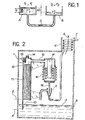
- FIG. 1 which represents the known state of the art, the reservoirs A and B containing superfluid helium are connected by means of a "superleak" S.
- a superleak generally produced by compressing in a tube a powdery material of small particle size, has the property of having a porosity such that a conventional fluid such as normal helium is practically incapable of circulating while the superfluid phase of helium, whose apparent viscosity is zero, can be flow freely.
- This effect is commonly called the Fountain effect.
- Liquid helium in the superfluid state retaining a non-zero surface tension while its viscosity is zero, is capable of wetting the walls of the reservoirs in perfect fashion, possibly mounting on an isothermal wall.
- the present invention specifically relates to an automatic device for regulating the level of helium in the superfluid state in a reservoir, which calls upon the particular properties known and recalled above of the superfluid helium, that is to say say to the Fontaine pressure effect and to the so-called Rollin film effect.
- the sampling of liquid helium in the superfluid state in its reservoir takes place at the liquid gas separation surface by a sampling body partially immersed in the liquid and along which a Rollin film is formed.
- the sampling surface of this body is variable as a function of altitude, makes it possible to obtain a sampling which is all the more important as the level of separation of the liquid phase and of the phase. carbonated is higher.
- the superleak which follows this sampling body makes it possible, using the calories provided by a heating resistance in the associated chamber, to create an overpressure in this chamber by Fountain effect and it is this which is used to inflate in a way a chamber with deformable and elastic walls and obtaining the displacement of a rod linked to said walls.
- This displacement represents, analogically, the variations in altitude of the superfluid helium surface.
- the control of the superfluid liquid helium inlet flow rate in the reservoir supply line at the position of this rod can be obtained by any known conventional means; according to an original characteristic of the invention, however, the supply line to the tank comprises an inlet valve whose preceding rod directly constitutes the needle.
- the needle having displacements which exactly represent those of the liquid helium-gaseous helium separation surface which it is wished to regulate precisely, it suffices to adjust this valve so that its closing takes place when the level of superfluid helium in the tank reaches the desired control altitude.
- Heating of the chamber into which the superleak opens can be obtained by any known means and in particular be carried out using a simple electrical resistance. Any other method of heating, by radiation or thermal conduction from zones with a higher temperature can also be used, for example as heat exchange with the helium penetrating into the supply line of the tank.
- the only condition to be respected is to supply this chamber with a sufficient quantity of calories so that the Fontaine pressure generated by the temperature difference between the reservoir and the chamber is sufficient to ensure the inflation of the chamber with deformable walls and the displacement of the rod regulating the admission.
- FIG. 2 represents in schematic section a tank containing superfluid helium.
- FIG. 2 shows the reservoir 1 which contains superfluid liquid helium 2, the separation surface 3 of which with the upper gas phase must be maintained automatically between certain defined limits 4 and 5.
- the reservoir 1 is of course set in communication via line 6 with the pumping means adapted to obtaining the desired pressures and temperatures.
- a supply line 7 opens into the chimney 6 of the tank 1 first in the form of a coil allowing the exchange of calories with the cold vapors which escape from the tank along the path of the arrow 8, then this pipe descends to the vicinity of the surface 3 via an inlet valve 9.
- the supply of the reservoir is done by the pipe 7 using fluid which can be either liquid helium or gaseous helium at pressures and temperatures such that after expansion in the valve 9, the helium be transformed into its superfluid variety.
- fluid which can be either liquid helium or gaseous helium at pressures and temperatures such that after expansion in the valve 9, the helium be transformed into its superfluid variety.
- a superfluid helium sampling body 10 is provided between level 4 and 5 and has a variable sampling surface from the zero value at level 4 to the maximum value at level 5.
- the sampling body 10 of variable section can be produced in different ways, and mention may be made, for example, of flared tubes, plates, wires, or sintered rods.
- the main thing is that the perimeter in contact with the superfluid helium 2 is variable, increasing regularly from level 4 to level 5. As soon as level 4 is reached by the surface 3 of the superfluid helium, a film of Rollin is created which rises along the sampling body 10. The flow of helium thus sampled increases progressively when the level of the liquid 3 rises to reach its maximum value when the level 5 is itself reached by the separation surface 3.
- the sampling body 10 is associated with a superleak 11 consisting of a pipe in which a powdery material of small particle size has been placed.
- This superleak 11 in turn opens into a heated room.l2, which is symbolized in FIG. 2 by the presence of an electrical resistance 13 located in this room, it being understood, as already explained above, that any other means of equivalent heating can be used as well without departing from the scope of the present invention.
- This chamber 12 communicates with a flow-controlled exhaust orifice 14 and, through the conduit 15, with a chamber with flexible, elastic and variable-volume deformable walls 16 whose bellows-shaped walls can move in translation along a vertical guide core 17.
- the end of the deformable walls of the chamber 16, in the form of bellows, is connected to the metal rod 18 which constitutes, in the example of FIG. 2, the needle of the valve 9.
- the flow of superfluid helium sampled by the sampling body 10 passes through the superleak 11 and enters the chamber 12 where the Fountain effect due to heating by the resistance 13 develops a pressure, communicated to the chamber 16 which, when expanding, causes the displacement of the metal rod 18.
- the exhaust orifice 14, the size of which is adjusted to a determined value guarantees the existence of a maximum gas pressure in the chamber 12.
- the heat input Q shown in 13 in the chamber 12 can be obtained by various means such as electric heating, thermal radiation or solid conduction from zones at higher temperature. It can also be produced by heat exchange with the fluid entering at 7 and supplying the valve 9 provided that this fluid is at a suitable temperature.
- the cold vapors 8 escaping from the tank 1 may or may not exchange heat with the supply fluid introduced at 7.
Landscapes
- Engineering & Computer Science (AREA)
- Physics & Mathematics (AREA)
- Fluid Mechanics (AREA)
- General Physics & Mathematics (AREA)
- Mechanical Engineering (AREA)
- General Engineering & Computer Science (AREA)
- Filling Or Discharging Of Gas Storage Vessels (AREA)
- Control Of Non-Electrical Variables (AREA)
- Investigating Or Analyzing Materials Using Thermal Means (AREA)
Applications Claiming Priority (2)
| Application Number | Priority Date | Filing Date | Title |
|---|---|---|---|
| FR8205644 | 1982-04-01 | ||
| FR8205644A FR2524666A1 (fr) | 1982-04-01 | 1982-04-01 | Dispositif de regulation automatique du niveau d'helium a l'etat suprafluide dans un reservoir |
Publications (2)
| Publication Number | Publication Date |
|---|---|
| EP0091850A1 true EP0091850A1 (de) | 1983-10-19 |
| EP0091850B1 EP0091850B1 (de) | 1986-06-11 |
Family
ID=9272645
Family Applications (1)
| Application Number | Title | Priority Date | Filing Date |
|---|---|---|---|
| EP83400630A Expired EP0091850B1 (de) | 1982-04-01 | 1983-03-25 | Automatischer Flüssigkeitsniveauregulator für superfluides Helium in einem Behälter |
Country Status (5)
| Country | Link |
|---|---|
| US (1) | US4485640A (de) |
| EP (1) | EP0091850B1 (de) |
| JP (1) | JPS58184615A (de) |
| DE (1) | DE3364032D1 (de) |
| FR (1) | FR2524666A1 (de) |
Families Citing this family (7)
| Publication number | Priority date | Publication date | Assignee | Title |
|---|---|---|---|---|
| US4796447A (en) * | 1987-07-09 | 1989-01-10 | Jacob Rabinow | Lock with key isolation using transfer tumblers |
| US4791788A (en) * | 1987-08-24 | 1988-12-20 | Quantum Design, Inc. | Method for obtaining improved temperature regulation when using liquid helium cooling |
| US4848093A (en) * | 1987-08-24 | 1989-07-18 | Quantum Design | Apparatus and method for regulating temperature in a cryogenic test chamber |
| JP2920427B2 (ja) * | 1991-01-21 | 1999-07-19 | 雪印乳業株式会社 | κ−カゼイングリコマクロペプチドの製造法 |
| US5647228A (en) * | 1996-07-12 | 1997-07-15 | Quantum Design, Inc. | Apparatus and method for regulating temperature in a cryogenic test chamber |
| US9618257B2 (en) * | 2010-06-09 | 2017-04-11 | Quantum Design International, Inc. | Gas-flow cryostat for dynamic temperature regulation using a fluid level sensor |
| US11425841B2 (en) | 2019-09-05 | 2022-08-23 | International Business Machines Corporation | Using thermalizing material in an enclosure for cooling quantum computing devices |
Citations (1)
| Publication number | Priority date | Publication date | Assignee | Title |
|---|---|---|---|---|
| FR2010178A1 (de) * | 1968-06-05 | 1970-02-13 | Philips Nv |
Family Cites Families (4)
| Publication number | Priority date | Publication date | Assignee | Title |
|---|---|---|---|---|
| GB945223A (en) * | 1961-09-22 | 1963-12-23 | Atomic Energy Authority Uk | Improvements in or relating to refrigerators |
| US3447333A (en) * | 1967-03-17 | 1969-06-03 | California Inst Res Found | Helium film refrigerator |
| NL6807902A (de) * | 1968-06-05 | 1969-12-09 | ||
| US4002039A (en) * | 1975-08-28 | 1977-01-11 | The Bendix Corporation | Self-regulating cryostat |
-
1982
- 1982-04-01 FR FR8205644A patent/FR2524666A1/fr active Granted
-
1983
- 1983-03-25 DE DE8383400630T patent/DE3364032D1/de not_active Expired
- 1983-03-25 EP EP83400630A patent/EP0091850B1/de not_active Expired
- 1983-03-31 JP JP58056814A patent/JPS58184615A/ja active Granted
- 1983-04-01 US US06/481,272 patent/US4485640A/en not_active Expired - Fee Related
Patent Citations (1)
| Publication number | Priority date | Publication date | Assignee | Title |
|---|---|---|---|---|
| FR2010178A1 (de) * | 1968-06-05 | 1970-02-13 | Philips Nv |
Non-Patent Citations (1)
| Title |
|---|
| CRYOGENICS, vol. 18, mars 1978, page 183, Guildford, G.B. * |
Also Published As
| Publication number | Publication date |
|---|---|
| FR2524666A1 (fr) | 1983-10-07 |
| DE3364032D1 (en) | 1986-07-17 |
| EP0091850B1 (de) | 1986-06-11 |
| JPS58184615A (ja) | 1983-10-28 |
| JPH0376486B2 (de) | 1991-12-05 |
| US4485640A (en) | 1984-12-04 |
| FR2524666B1 (de) | 1984-05-11 |
Similar Documents
| Publication | Publication Date | Title |
|---|---|---|
| EP0091850B1 (de) | Automatischer Flüssigkeitsniveauregulator für superfluides Helium in einem Behälter | |
| FR2674446A1 (fr) | Dispositif de filtration et de communication entre l'atmosphere et l'interieur d'un carter. | |
| FR2479402A1 (fr) | Dispositif de purge d'air de systemes de canalisations | |
| EP0038769A2 (de) | Verfahren und Anlagen, um ein Wärmetauschfluidum in einem mit einer Wärmequelle und einer Kältequelle versehenen geschlossenen Kreislauf umlaufen zu lassen | |
| FR2512164A1 (fr) | Regulateur de pression comportant un dispositif de compensation de temperature | |
| EP0489628B1 (de) | Verdampfungskühlverfahren für eine Brennkraftmaschine und Einrichtung zur Durchführung dieses Verfahrens | |
| WO2016083092A1 (fr) | Dispositif de prelevement d'un fluide sous pression equipe de moyens pour augmenter le volume de la chambre d'echantillonnage | |
| FR2466762A1 (fr) | Instrument de mesure de pression pour hautes temperatures | |
| EP0106755B1 (de) | Verfahren und Einrichtung zum Herbeiführen einer Vielzahl hydrodynamischer Funktionen in einem Strom, zusammengesetzt aus wenigstens zwei Phasen | |
| WO1993016365A1 (fr) | Procede et dispositif pour prelever un echantillon d'eau a une profondeur determinee | |
| FR2511175A1 (fr) | Appareil de controle d'agent de refroidissement pour un reacteur nucleaire | |
| EP3259226B1 (de) | Adapter und verfahren zum füllen eines flüssigkeitskreislaufs | |
| EP0064430B1 (de) | Absorberstab für Kernreaktor | |
| FR2648724A1 (fr) | Dispositif de distillation en laboratoire | |
| FR2466800A1 (fr) | Soupape | |
| EP0128129A2 (de) | Ventil, insbesondere für Flüssiggas | |
| BE435563A (de) | ||
| EP1977048B1 (de) | Druckmessersonde und druckmesser | |
| FR2633007A1 (fr) | Reservoir d'huile de moteur aeronautique muni d'un dispositif de trop plein | |
| FR2657140A1 (fr) | Limiteur de debit d'un fluide. | |
| FR2648863A1 (fr) | Procede et dispositif de prelevement d'un echantillon de fluide de gisement | |
| FR2464538A1 (fr) | Dispositif etalon pour l'emission de produits de fission pour la detection de rupture de gaine dans un reacteur nucleaire | |
| EP0108044B1 (de) | Wasserflussregeleinrichtung zum Kühlen von Bohrlöchern bei der Vergasung von Kohle | |
| EP0271401B1 (de) | Entleerungsapparat für Laborreaktoren | |
| FR2570846A1 (fr) | Dispositif de surveillance de la pression dans une enceinte et circuits de regulation utilisant ce dispositif |
Legal Events
| Date | Code | Title | Description |
|---|---|---|---|
| PUAI | Public reference made under article 153(3) epc to a published international application that has entered the european phase |
Free format text: ORIGINAL CODE: 0009012 |
|
| AK | Designated contracting states |
Designated state(s): DE GB NL |
|
| 17P | Request for examination filed |
Effective date: 19840406 |
|
| GRAA | (expected) grant |
Free format text: ORIGINAL CODE: 0009210 |
|
| AK | Designated contracting states |
Kind code of ref document: B1 Designated state(s): DE GB NL |
|
| REF | Corresponds to: |
Ref document number: 3364032 Country of ref document: DE Date of ref document: 19860717 |
|
| PLBE | No opposition filed within time limit |
Free format text: ORIGINAL CODE: 0009261 |
|
| STAA | Information on the status of an ep patent application or granted ep patent |
Free format text: STATUS: NO OPPOSITION FILED WITHIN TIME LIMIT |
|
| 26N | No opposition filed | ||
| PGFP | Annual fee paid to national office [announced via postgrant information from national office to epo] |
Ref country code: DE Payment date: 19950309 Year of fee payment: 13 |
|
| PGFP | Annual fee paid to national office [announced via postgrant information from national office to epo] |
Ref country code: GB Payment date: 19950310 Year of fee payment: 13 |
|
| PGFP | Annual fee paid to national office [announced via postgrant information from national office to epo] |
Ref country code: NL Payment date: 19950331 Year of fee payment: 13 |
|
| PG25 | Lapsed in a contracting state [announced via postgrant information from national office to epo] |
Ref country code: GB Effective date: 19960325 |
|
| PG25 | Lapsed in a contracting state [announced via postgrant information from national office to epo] |
Ref country code: NL Effective date: 19961001 |
|
| GBPC | Gb: european patent ceased through non-payment of renewal fee |
Effective date: 19960325 |
|
| NLV4 | Nl: lapsed or anulled due to non-payment of the annual fee |
Effective date: 19961001 |
|
| PG25 | Lapsed in a contracting state [announced via postgrant information from national office to epo] |
Ref country code: DE Effective date: 19961203 |