EP0092538A2 - Schmelzverfahren für Feststoffe und Vorrichtung zur Ausführung des Verfahrens und hergestellte Gegenstände - Google Patents
Schmelzverfahren für Feststoffe und Vorrichtung zur Ausführung des Verfahrens und hergestellte Gegenstände Download PDFInfo
- Publication number
- EP0092538A2 EP0092538A2 EP83870034A EP83870034A EP0092538A2 EP 0092538 A2 EP0092538 A2 EP 0092538A2 EP 83870034 A EP83870034 A EP 83870034A EP 83870034 A EP83870034 A EP 83870034A EP 0092538 A2 EP0092538 A2 EP 0092538A2
- Authority
- EP
- European Patent Office
- Prior art keywords
- solid particles
- plates
- external heat
- heat input
- machine
- Prior art date
- Legal status (The legal status is an assumption and is not a legal conclusion. Google has not performed a legal analysis and makes no representation as to the accuracy of the status listed.)
- Withdrawn
Links
Images
Classifications
-
- C—CHEMISTRY; METALLURGY
- C04—CEMENTS; CONCRETE; ARTIFICIAL STONE; CERAMICS; REFRACTORIES
- C04B—LIME, MAGNESIA; SLAG; CEMENTS; COMPOSITIONS THEREOF, e.g. MORTARS, CONCRETE OR LIKE BUILDING MATERIALS; ARTIFICIAL STONE; CERAMICS; REFRACTORIES; TREATMENT OF NATURAL STONE
- C04B35/00—Shaped ceramic products characterised by their composition; Ceramics compositions; Processing powders of inorganic compounds preparatory to the manufacturing of ceramic products
- C04B35/622—Forming processes; Processing powders of inorganic compounds preparatory to the manufacturing of ceramic products
- C04B35/653—Processes involving a melting step
-
- B—PERFORMING OPERATIONS; TRANSPORTING
- B22—CASTING; POWDER METALLURGY
- B22F—WORKING METALLIC POWDER; MANUFACTURE OF ARTICLES FROM METALLIC POWDER; MAKING METALLIC POWDER; APPARATUS OR DEVICES SPECIALLY ADAPTED FOR METALLIC POWDER
- B22F3/00—Manufacture of workpieces or articles from metallic powder characterised by the manner of compacting or sintering; Apparatus specially adapted therefor ; Presses and furnaces
- B22F3/02—Compacting only
- B22F3/093—Compacting only using vibrations or friction
-
- B—PERFORMING OPERATIONS; TRANSPORTING
- B29—WORKING OF PLASTICS; WORKING OF SUBSTANCES IN A PLASTIC STATE IN GENERAL
- B29B—PREPARATION OR PRETREATMENT OF THE MATERIAL TO BE SHAPED; MAKING GRANULES OR PREFORMS; RECOVERY OF PLASTICS OR OTHER CONSTITUENTS OF WASTE MATERIAL CONTAINING PLASTICS
- B29B13/00—Conditioning or physical treatment of the material to be shaped
- B29B13/02—Conditioning or physical treatment of the material to be shaped by heating
- B29B13/022—Melting the material to be shaped
-
- C—CHEMISTRY; METALLURGY
- C03—GLASS; MINERAL OR SLAG WOOL
- C03B—MANUFACTURE, SHAPING, OR SUPPLEMENTARY PROCESSES
- C03B19/00—Other methods of shaping glass
- C03B19/06—Other methods of shaping glass by sintering, e.g. by cold isostatic pressing of powders and subsequent sintering, by hot pressing of powders, by sintering slurries or dispersions not undergoing a liquid phase reaction
Definitions
- the present invention relates to a new process for melting solid particles without external heat supply and to a fusion machine based on this principle as well as to the products obtained.
- without external heat supply it is meant that the process itself generates its own heat by energy conversion and that there is therefore no direct supply of heat by heating.
- the raw materials are previously melted before being transformed into finished or semi-finished products.
- This melting technology generally requires the use of high temperatures and therefore consumes a lot of energy.
- the use of high temperatures poses many problems for the production of the processing equipment.
- the melting process applied to materials made up of different elements finds limits because certain materials are distributed in a non-uniform manner and give heterogeneous end products.
- the use of high temperatures does not allow the incorporation in sufficient quantity of elements which are too volatile and yet capable of improving the properties of the final product.
- the raw materials used are agglomerated under the effect of pressure and temperature, these two parameters occurring simultaneously or successively.
- the present invention aims to remedy these various drawbacks and relates to a new process for melting solid particles without external heat supply, characterized in that the solid particles are subjected to the combined action of a pressure greater than 50 MPa and a shear gradient greater than 5 s -1 , so that the friction between the particles causes the fusion. It also relates to a melting machine applying this process as well as the products obtained.
- the new fusion process does not use external heat, that is, it generates its own heat by converting mechanical friction energy into thermal energy.
- fusion By fusion, one also understands the neighboring states of the fusion such as the pasty state, the softening, the plasticization or the semi-fusion.
- the new process known as fusion presents the great advantage of giving finished products having the physical characteristics of those resulting from a traditional fusion, while being obtained at temperatures much lower than the melting temperatures of the raw materials used.
- solid particles any inorganic and / or organic material of origin and of any kind capable of softening, melting or being transformed under the action of heat. These solid particles may possibly give off gases. They can also react with one another to form homogeneous fusion products such as, for example, glassy materials.
- solid particles are used in the divided state in the form of particles, granules, grains, chips, beads or powders. All shapes and profiles can be used, provided that they generate, when subjected to the combined action of high pressure and shear gradient, sufficient friction forces to cause fusion, term taken in the broad sense as said above.
- the particle size of the solid particles can be arbitrary but is preferably chosen from the range of 100 ⁇ m to 1 mm.
- a fine particle size is desirable in order to obtain the maximum contact points between the particles, this promoting an efficient conversion of the mechanical friction energy into heat energy.
- solid particles of inorganic nature which can be used according to the present invention, alone or in mixtures in all proportions, let us quote vitreous materials, ceramic materials, metals, ferrous metals, non-ferrous metals, their alloys, their oxides , their salts and mixtures thereof.
- Ceramic materials include both traditional ceramics such as those used for sanitary purposes, etc. and new ceramics, for example metallic ceramics such as carbides, metallic nitrides or others.
- the materials used alone or in mixtures can be chosen from the elements appearing in Mendeletev's periodic table.
- Ferrous metals include iron and its alloys.
- Non-ferrous metals include, for example, copper, zinc, tin, antimony, aluminum, lead and their alloys.
- the solid particles can be alloys of the various metals and in particular ferrous and non-ferrous materials and also comprise various oxides of these metals; it is also possible to use salts and other compounds formed from any cations and / or anions.
- Examples include alloys such as cast iron, steel, stainless steel, special steels, bronzes, brass.
- oxides include magnesium, aluminum, silicon, zinc, lead, zirconium, lithium, etc ...
- the solid particles of organic nature used according to the present invention must be capable of softening, melting or hardening under the action of heat.
- the organic materials meeting this condition are in particular synthetic polymers, their alloys and mixtures, whether they are thermoplastic or thermosetting.
- synthetic polymer is understood to mean in particular homopolymers, copolymers, terpolymers whether they are of synthetic or artificial nature.
- synthetic polymers include polyamides, polyesters such as polyethylene terephthalate, polycarbonate, polyolefins such as polyethylene and polypropylene, vinyl derivatives such as polyvinyl chloride, polystyrene, polyacrylates and polymethacrylates and polyurethanes.
- Synthetic polymers with a high melting point for which the conventional techniques of implementation pose numerous problems, can be advantageously used in the present invention.
- These include polysulfones, polyphenylene oxides and sulfides, polyimides. These various polymers can be used in mixtures in all proportions and can be added with various other compounds as used for the manufacture of technical plastics and composites.
- Synthetic alloys consisting of a mixture of polymers formed from two or more components linked by intermolecular forces, can also be used as solid particles according to the present invention.
- Examples include alloys based on ⁇ -crylonitrile-butadiene-styrene (ABS), polyvinyl chloride (PVC), polycarbonate, polyolefins and thermosetting resins linked to elastomers and thermoplastics.
- the solid particles are subjected to the combined action of a pressure greater than 50 MPa and a shear gradient greater than 5 s- 1 , so that the friction between the particles causes the fusion.
- the increasing pressure exerted on the particles has the effect of compressing and / or crushing them and thus, provoking an increasingly intimate contact between them.
- the fusion propagates from one zone to another to gain the entire mass of the particles.
- the melt thus obtained can then be cooled or used directly for forming finished or semi-finished products either by casting, molding, extrusion or injection.
- the thermal equilibrium thus obtained depends on the nature of the solid particles used and on the operating conditions chosen.
- the temperature rise is always very rapid and the self-regulation of the system occurs regularly at the start of the third phase described above.
- the amount of energy required to melt the product is 1.5 KWh / kg.
- the pressure exerted on the solid particles must be greater than 50 MPa so that the friction forces generated by the shearing on the different particles are sufficient to initiate the fusion.
- the pressure favors the number of points of contact between the solid particles and thus allows a better propagation of the heat within the mass.
- the pressure is greater than 50 MPa and preferably the pressure is between 50 and 1000 MPa. In general, we work in an area between 70 and 700 MPa.
- the pressure must be such that, depending on the raw materials used, the solid particles are in intimate contact and capable, under the combined action of the shear gradient, of developing friction forces such as the particles are merging.
- the shear gradient used in conjunction with the pressure according to the present invention is greater than 5 s- 1 and preferably is between 5 and 8000 s- 1 .
- the action of the pressure and the shear gradient on the solid particles can be simultaneous or not. In general, pressure is applied gradually after the shear gradient has been induced within the solid particles.
- the present invention also relates to a machine for melting solid particles, characterized in that the particles are subjected, in a closed enclosure, to the combined action of a pressure greater than 50 MPa and a higher shear gradient at 5 s- 1 between two plates, at least one of which is rotatable.
- One or possibly both of the plates are rotatable so as to create the shear gradient. If the two plates are rotary, the directions of rotation can be identical or opposite.
- the pressure is exerted on one of the plates or possibly on both.
- one of the plates is rotary and the other transmits the pressure to the mass of solid particles present in the closed enclosure.
- the plates Under the action of the pressure exerted on at least one of the plates, at least one of which is rotatable and generates the shear gradient, the plates come together and produce, between the solid particles, friction causing their fusion.
- the solid particles are introduced in the divided state by a feed channel opening into the closed enclosure. As soon as the solid particles have filled the entire closed enclosure, the opening of the feed channel is obstructed and the mass of the particles is then subjected to the action of pressure with a view to a first compacting. Then, the pressure is released before rotating one of the plates to generate the shear gradient. The solid particles are then subjected to the action of increasing pressure.
- the pressure is exerted, via one or more hydraulic cylinders, at least one of the plates.
- the mass of solid particles is subjected, first to the action of the shear gradient Lement by rotation of at least one of the plates and then the action of increasing pressure.
- the process of melting the particles present in the closed enclosure of the machine is carried out according to the three phases described above and comprising the compression and / or the crushing of the particles, the initiation of the fusion and the propagation of the fusion .
- the fusion takes place at the locations of maximum shear, namely at the interface between a fixed part and a rotating part.
- the fusion machine comprises two plates and a cylinder which may or may not be integral with one of the plates, to form the closed enclosure, a supply channel for the solid particles opening into said enclosure, a means for pressurizing one at least trays, and a means for rotating one at least of the trays.
- the cylinder forms with the trays the closed enclosure.
- This cylinder can be entirely secured to one of the plates and in this case undergoes all the rotational and / or translational movements of said plate. If the cylinder is not entirely integral with one of the plates, it then has a translational movement relative to this plate, which continues to drive it in rotation.
- the feed channel for solid particles has a hole opening into the closed enclosure. This orifice is made in the cylinder constituting a part of the enclosure.
- the orifice In the case where the orifice is made in the cylinder, its opening and closing is done by relative displacement of the cylinder relative to one of the plates or by a shutter system with independent control of the fusion machine.
- the orifice In the case where the orifice is made in one of the plates, its opening and closing are done by a shutter system independently controlled by the fusion machine.
- the means for pressurizing at least one of the plates is of a known type and consists, for example, of a hydraulic press.
- the rotation of at least one of the plates is obtained by any known means, for example, an electric motor associated with a variator and a speed reducer.
- the machine for melting solid particles without external heat supply may include devices for forming, casting, molding, injection and extrusion. Such devices can be arranged axially or radially.
- the devices are arranged in the direction of the application of pressure. Radially means that the devices are arranged in a plane perpendicular to the direction of pressure application.
- the forming devices are connected to the closed enclosure by an injection channel.
- the forming device can be secured to the cylinder.
- the opening and closing of the injection channel can be obtained either by any known device independent of the fusion machine, or by the relative displacement of the cylinder relative to the plates.
- the forming device can be integral with one of the plates.
- the opening and closing of the injection channel must in this case be obtained by an independent device of known type; for example by the movement of a piston sliding in the injection channel.
- the sufficiently short duration of implementation makes it possible to obtain new materials comprising constituents considered to be too unstable at the temperatures usually used in conventional methods.
- the raw materials to be used can be very diverse and the process lends itself to any mixing, it is possible to obtain varied and new products of homogeneous structure.
- An example is glass loaded with selenium. By conventional glass melting, 0.1 to 0.2% selenium can be introduced into it. The claimed process makes it possible to introduce 3 to 4% into the glass without any difficulty and even more.
- the product obtained can be of alveolar structure.
- the claimed process finds numerous applications, particularly in the fields of metallurgy, the vitreous materials industry, electrical engineering and electronics.
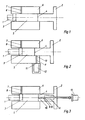
- the fusion machine comprises two plates 1 and 2, the internal faces 3 and 4 of which form part of the walls of the closed enclosure 5.
- the shear gradient is obtained by the rotation of at least one of the plates. If the two plates are rotary, their direction of rotation is identical or opposite.
- the pressure is exerted on at least one of the plates or on both by known transmission means.
- the melting machine includes the device as shown in Figure 1 in the working position of fusion.
- the plate 1 closes in this position the opening 8 of the supply channel 7.
- the fusion machine comprises a forming device arranged radially and comprising an injection channel 9 with an orifice 10 opening into the closed enclosure 5.
- the injection channel 9 opens at 11 into the forming mold 12; this mold may include one or more forming impressions.
- the opening of the orifice 10 of the injection channel 9 is obtained by the longitudinal displacement of the cylinder 6.
- FIG. 3 shows a melting device as shown in Figure 2 and comprising a forming device 12 arranged axially.
- This forming device differs from FIG. 2 in that the injection channel 9 includes an orifice 10, the closure and opening of which are obtained by a schematic device 13. This channel opens out at 11 into the forming device 12.
- the control of the closing and opening device 13 of the orifice 10 is independent of the melting machine proper.
- This command can consist of a pneumatic or hydraulic cylinder which controls a rod closing the orifice 10.
- the fusion machine used for carrying out this example is shown diagrammatically in FIG. 3.
- the fusion machine comprises a turntable 1, which rotates the cylinder 6, but which can move longitudinally relative to this cylinder.
- the fusion machine also comprises a fixed plate 2 including the forming device, and to which pressure is applied.
- the material used is zinc powder with a particle size between 150 and 250 ⁇ m.
- the powder is introduced into the closed enclosure 5 via the feed channel 7 and then undergoes compaction at a pressure of 72 MPa.
- the pressure is then released and the piston 1 and the cylinder 6 are rotated at a speed of 100 rpm, which induces in the powder a shear gradient of 32 s- 1 .
- a pressure of 72 MPa is then applied via the piston 2.
- the temperature increases, and after 20 s. stabilizes at the working temperature of 180 ° C.
- the pressure is then increased to 107 MPa and the material is injected into the forming device comprising four impressions of test pieces.
- the energy expenditure to carry out the fusion and the injection of four perfectly homogeneous test pieces and of qualities comparable to those obtained by traditional processes is 0.44 KWh / kg. This expenditure would be approximately 3.18 KWh / kg for a traditional process.
- Example 1 The procedure of Example 1 was applied to polystyrene granules with a particle size of 5 mm.
- the temperature stabilizes after 15 s. at a working temperature of 70 ° C.
- the energy expenditure to carry out the fusion and the injection of the four test pieces is 0.92 KWh / kg.
- the energy expenditure for a traditional process is around 2.5 KWh / kg.
Landscapes
- Engineering & Computer Science (AREA)
- Chemical & Material Sciences (AREA)
- Manufacturing & Machinery (AREA)
- Materials Engineering (AREA)
- Ceramic Engineering (AREA)
- Mechanical Engineering (AREA)
- Organic Chemistry (AREA)
- Inorganic Chemistry (AREA)
- Structural Engineering (AREA)
- Dispersion Chemistry (AREA)
- Physics & Mathematics (AREA)
- Thermal Sciences (AREA)
- Processing And Handling Of Plastics And Other Materials For Molding In General (AREA)
- Powder Metallurgy (AREA)
Applications Claiming Priority (2)
| Application Number | Priority Date | Filing Date | Title |
|---|---|---|---|
| BE207852 | 1982-04-16 | ||
| BE0/207852A BE892879A (fr) | 1982-04-16 | 1982-04-16 | Nouveau procede de fusion de particules solides machine appliquant ce procede et produits ainsi obtenus. |
Publications (2)
| Publication Number | Publication Date |
|---|---|
| EP0092538A2 true EP0092538A2 (de) | 1983-10-26 |
| EP0092538A3 EP0092538A3 (de) | 1985-06-12 |
Family
ID=3843522
Family Applications (1)
| Application Number | Title | Priority Date | Filing Date |
|---|---|---|---|
| EP83870034A Withdrawn EP0092538A3 (de) | 1982-04-16 | 1983-03-28 | Schmelzverfahren für Feststoffe und Vorrichtung zur Ausführung des Verfahrens und hergestellte Gegenstände |
Country Status (1)
| Country | Link |
|---|---|
| EP (1) | EP0092538A3 (de) |
Family Cites Families (4)
| Publication number | Priority date | Publication date | Assignee | Title |
|---|---|---|---|---|
| US2399592A (en) * | 1943-09-09 | 1946-04-30 | Dow Chemical Co | Method of making molded thermoplastic articles |
| DE1520152A1 (de) * | 1963-05-29 | 1969-07-17 | Roemmler Gmbh H | Veraenderung der Struktur von hochmolekularen thermoplastischen Kunststoffen |
| US3523147A (en) * | 1967-09-28 | 1970-08-04 | Usm Corp | Plastication of thermoplastic materials |
| US3717427A (en) * | 1970-12-03 | 1973-02-20 | A Bodine | Sonic apparatus for working plastic material |
-
1983
- 1983-03-28 EP EP83870034A patent/EP0092538A3/de not_active Withdrawn
Also Published As
| Publication number | Publication date |
|---|---|
| EP0092538A3 (de) | 1985-06-12 |
Similar Documents
| Publication | Publication Date | Title |
|---|---|---|
| EP0238425B1 (de) | Verfahren und Vorrichtung zur Herstellung hitzebeständiger Materialien durch Induktion | |
| EP0003701B1 (de) | Verfahren und Vorrichtung zum Extrudieren eines vernetzten Produkts | |
| EP2801560A2 (de) | Mischmaschine, Mischung von Rohstoff für die Pulvermetallurgie | |
| JPS58502002A (ja) | シキソトロピ−性物質の製造法 | |
| EP3784720B1 (de) | Thermoplastische zusammensetzung mit einer mikrowellendepolymerisationssensibilisierungsverbindung | |
| EP0220103A1 (de) | Unmittelbar pressbares Maltitolpulver und Verfahren zu dessen Herstellung | |
| WO1995017998A1 (fr) | Procede de traitement d'une poudre de talc en vue de l'incorporer dans une matiere thermoplastique | |
| EP2765123B1 (de) | Zwangsmischer von Rohstoff für die Pulvermetallurgie | |
| FR2567803A1 (fr) | Procede de fabrication d'objets moules a base de composite d'aluminium renforce de fibres | |
| EP0092538A2 (de) | Schmelzverfahren für Feststoffe und Vorrichtung zur Ausführung des Verfahrens und hergestellte Gegenstände | |
| BE892879A (fr) | Nouveau procede de fusion de particules solides machine appliquant ce procede et produits ainsi obtenus. | |
| EP2726262B1 (de) | Verfahren zur herstellung von farbigen keramischen teilen durch pim | |
| KR102790828B1 (ko) | 레이저 어블레이션을 적용하는 코팅에 사용되는 타겟 물질에 그래핀-기반 첨가제를 첨가하는 방법 | |
| FR2499967A1 (fr) | Procede et dispositif de fabrication par frittage sous charge de pieces riches en bore et pieces riches en bore | |
| BE891470A (fr) | Procede et appareil de compression d'une poudre polymere en des objets faconnes a leur pleine densite, et produits obtenus | |
| EP0311520A1 (de) | Verfahren und Maschine zur Herstellung eines Endproduktes mittels Extrusion, ausgehend von einem thermoplastischen extrudierfähigen Material hygroskopischer Natur | |
| FR2723328A1 (fr) | Composition pour produit agglomere comprenant une charge vegetale et du sucre, produit agglomere et son procede de preparation | |
| EP0011535B1 (de) | Verfahren zum Schmieden von Polybuten-(1) im festen Zustand | |
| JP2005501766A (ja) | 周面と自由体積との特殊な比、若しくはスクリュー内径と外径との特殊な比を用いて、連続的な混合及び処理プロセスを行うための方法 | |
| FR2596690A1 (fr) | Procede de fabrication de pieces moulees en matiere synthetique | |
| EP1066946B1 (de) | Verfahren zur Herstellung von optischen Teilen für Fahrzeugbeleuchtung oder -Signalisierung | |
| WO2001077223A1 (fr) | Materiaux composites polymere/polymere a haute teneur en phase dispersee amorphe et procede pour leur preparation | |
| TWI816378B (zh) | 石墨烯複合材料及其製造方法 | |
| EP4072818B1 (de) | Verfahren zur herstellung eines massivteils durch heisssinterbehandlung von mindestens einem festen organischen material | |
| CH708039A2 (fr) | Malaxage de matière première pour métallurgie des poudres. |
Legal Events
| Date | Code | Title | Description |
|---|---|---|---|
| PUAI | Public reference made under article 153(3) epc to a published international application that has entered the european phase |
Free format text: ORIGINAL CODE: 0009012 |
|
| AK | Designated contracting states |
Designated state(s): AT BE CH DE FR GB IT LI LU NL SE |
|
| PUAL | Search report despatched |
Free format text: ORIGINAL CODE: 0009013 |
|
| AK | Designated contracting states |
Designated state(s): AT BE CH DE FR GB IT LI LU NL SE |
|
| 17P | Request for examination filed |
Effective date: 19850704 |
|
| 17Q | First examination report despatched |
Effective date: 19860214 |
|
| STAA | Information on the status of an ep patent application or granted ep patent |
Free format text: STATUS: THE APPLICATION IS DEEMED TO BE WITHDRAWN |
|
| 18D | Application deemed to be withdrawn |
Effective date: 19860625 |
|
| RIN1 | Information on inventor provided before grant (corrected) |
Inventor name: VIATOUR, GEORGES JULES RENE G. |