EP0092573B1 - Dispositif de frein - Google Patents
Dispositif de frein Download PDFInfo
- Publication number
- EP0092573B1 EP0092573B1 EP82903423A EP82903423A EP0092573B1 EP 0092573 B1 EP0092573 B1 EP 0092573B1 EP 82903423 A EP82903423 A EP 82903423A EP 82903423 A EP82903423 A EP 82903423A EP 0092573 B1 EP0092573 B1 EP 0092573B1
- Authority
- EP
- European Patent Office
- Prior art keywords
- disc
- brake
- caliper member
- air
- brake assembly
- Prior art date
- Legal status (The legal status is an assumption and is not a legal conclusion. Google has not performed a legal analysis and makes no representation as to the accuracy of the status listed.)
- Expired
Links
Images


Classifications
-
- F—MECHANICAL ENGINEERING; LIGHTING; HEATING; WEAPONS; BLASTING
- F16—ENGINEERING ELEMENTS AND UNITS; GENERAL MEASURES FOR PRODUCING AND MAINTAINING EFFECTIVE FUNCTIONING OF MACHINES OR INSTALLATIONS; THERMAL INSULATION IN GENERAL
- F16D—COUPLINGS FOR TRANSMITTING ROTATION; CLUTCHES; BRAKES
- F16D55/00—Brakes with substantially-radial braking surfaces pressed together in axial direction, e.g. disc brakes
- F16D55/02—Brakes with substantially-radial braking surfaces pressed together in axial direction, e.g. disc brakes with axially-movable discs or pads pressed against axially-located rotating members
- F16D55/22—Brakes with substantially-radial braking surfaces pressed together in axial direction, e.g. disc brakes with axially-movable discs or pads pressed against axially-located rotating members by clamping an axially-located rotating disc between movable braking members, e.g. movable brake discs or brake pads
- F16D55/228—Brakes with substantially-radial braking surfaces pressed together in axial direction, e.g. disc brakes with axially-movable discs or pads pressed against axially-located rotating members by clamping an axially-located rotating disc between movable braking members, e.g. movable brake discs or brake pads with a separate actuating member for each side
-
- F—MECHANICAL ENGINEERING; LIGHTING; HEATING; WEAPONS; BLASTING
- F16—ENGINEERING ELEMENTS AND UNITS; GENERAL MEASURES FOR PRODUCING AND MAINTAINING EFFECTIVE FUNCTIONING OF MACHINES OR INSTALLATIONS; THERMAL INSULATION IN GENERAL
- F16D—COUPLINGS FOR TRANSMITTING ROTATION; CLUTCHES; BRAKES
- F16D65/00—Parts or details
- F16D65/78—Features relating to cooling
- F16D65/84—Features relating to cooling for disc brakes
- F16D65/847—Features relating to cooling for disc brakes with open cooling system, e.g. cooled by air
Definitions
- This invention relates to a disc brake assembly of the type as indicated in the precharacterizing portion of claim 1.
- a disc brake of this type is already shown in US-A-3059 730.
- the present invention is characterized as specified in the second part of claim 1 and is directed to a caliper disc brake cooling system wherein the rotatable brake disc and its adjacent supports are fully enclosed in an air tight housing.
- Such housing includes the caliper member which has the moveable piston members that upon actuation operate on the braking pads or members which exert the braking force on the brake disc which action generates heat.
- Coolant means are provided to direct a flow of air over and around the brake disc which is then exhausted to atmosphere.
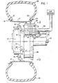
- FIG. 1 an axle 10 that extends laterally across a vehicle covered by a stationary axle housing 11.
- Axle 10 drives a planetary gear unit which is located within gear housing or support 12.
- Housing 12 is a hub and rotates therewith.
- Housing 12 is suitably secured to an annular support or plate 13, which plate 13 has a conical portion 18 with a flanged portion 24.
- Support 13 has a plurality of circumferentially spaced bores on its outer periphery that receive bolts 14 and nuts 15 for securing a wheel flange 16 thereto.
- Wheel flange 16 is connected to a wheel rim 17 which has spaced rim flanges 19 and 20 for mounting beads 21 and 22 of a tire 23 thereon.
- the rim is shown as being one piece construction for illustration purposes, such rim has generally two piece annular sections defining co-axially aligned peripheral portions for mounting the beads of a tire 23 thereon with rim flanges such as elements 19 and 20 secured on the outboard ends of the rim sections to retain the tire 23 thereon.
- Such rim flanges 19 and 20 extend radially outwardly from the wheel rim 17 to abut the outboard sides of the tire beads.
- the flanged portion 24 of annular support 13 has a plurality of circumferentially spaced bores to provide means for attaching an annular spacer 25 thereto.
- a brake disc 26 Suitably secured to the spacer 25 is a brake disc 26 having a pair of opposed friction faces 27 and 28.
- an annular seal flange 30 Also secured to spacer 25 is an annular seal flange 30 having an annular peripheral surface 31 that will function as a sealing means in cooperation with a stationary annular seal 32 to be described.
- a caliper brake assembly 35 is mounted within the wheel well envelope of the wheel rim 17 and includes a U-shaped caliper number 36 which straddles or overlies a peripheral portion of the brake disc 26.
- the caliper member 36 has an annular seal retaining plate 40 attached to the outboard side thereof and a semi circular plate or adapter cover 41 along with semi circular adapter 43 secured to the inboard side thereof.
- a cylindrically shaped ring 42 is suitably attached to the inner periphery of annular plate 40. Located within the cylindrical ring 42 are the annular seals 32 having their inner peripheral surfaces operatively contacting the rotating surface 31 of annular seal flange 30.
- Annular seals 32 are retained on the cylindrical ring 42 by the inner circumferentially extending edge 44 of ring 42 and an annular plate member 45 that is secured to the outer circumferential side of ring 42.
- An arcuately shaped cover 50 has its respective side edges attached to the annular seal retaining plate 40 and the circular plate 41 and its respective ends attached to caliper member 36. The cover 50 cooperates with the plates 40, 41, adapter 43 and caliper member 36 to define a housing which has a closed chamber 55 that encompasses the brake disc 26 of the brake assembly.
- the inner periphery of adapter 43 and circular plate 41 and the inner periphery of caliper member 36 are attached to a pair of circular plates 51 and 52 which form part of the axle housing 11 to thereby assure a fully enclosed chamber 55.
- the caliper member 36 is rigidly fastened to flanges 51 and 52 which are members of the nonrotatable portion of the axle housing assembly thereby preventing rotation of the caliper member 36.
- the caliper member 36 is a generally U-shaped housing which is arcuately shaped or curved to encompass the upper portion of brake disc 26. Each side portion of the caliper member 36 has a pair of spaced bores 56-57 respectively that communicate inwardly towards the brake disc 26.
- Each side of the caliper member 36 has a pair of bores 58 spaced laterally of the bores 56-57, which bores 58 extend into and communicate with the chamber 55.
- Torque pins are located in each of the respective bores 58 to support lining carriers 60 in a manner well known in the art.
- Brake linings 61 are suitably secured to the lining carriers 60 and are adapted to frictionally engage the respective sides of disc 26 to effect a braking action.
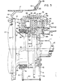
- Pistons 65 located in spaced bores 56 and pistons 66 located in spaced bores 57 are slidably received therein and are subject to linear movement for exerting a thrust on the carriers 60 which forces are transmitted to brake linings 61 of friction material for movement into engagement with the brake disc 26.
- each piston 65 and 66 Rearwardly of each piston 65 and 66 are chambers that are adapted to receive pressurized fluid for actuation of the pistons.
- a conduit 69 connects the braking fluid to a passageway 70 (Fig. 2) that communicates with a chamber 71 behind pistons 65.
- Chamber 71 adjacent to pistons 65 communicates with the chamber behind pistons 65 and via passageways 72 (Fig. 3) to the chamber 73 (Fig. 3) behind pistons 66.
- the admission of pressurized fluids into conduit 69 will pressurize the respective chambers behind pistons 65-66 which in turn provide a force on the brake linings 61-61 which in turn are applied against the brake disc 26.
- the U-shaped caliper member 36 which straddles the upper portion of the periphery of brake disc 26 has a pair of spaced inlet openings 80-81 that interconnect the central chamber 55 to an inlet counduit 82 via passageway 83 and 84 respectively.
- the passageways that lead to the openings 80 and 81 lie along linear lines that intersect the disc 26 at an acute angle to impart a flow of air along the opposite faces of the brake disc 26 in a counter-clockwise direction as viewed in Fig. 2.
- Conduit 82 is suitably connected to a bore 85 (Fig. 4) in such caliper member 36.
- a flow divider 86 is located within conduit 82 at its juncture with passageways 83 and 84 to divide the flow of air equally to such reapective passageways 83 and 84.
- the U-shaped caliper member 36 also has a centrally disposed opening 90 interconnecting chamber 55 (Fig. 5) to an outlet or exhaust conduit 91 via passageway 92.
- the exhaust opening 90 is closely adjacent the air inlet openings 80 and 81 such that the forced counterclockwise rotation of air will travel substantially 360 degrees before exciting via openings 90.
- the invention above described refers to a single disc 26 whereas a plurality of rotatable discs or members may be used in cooperation with a plurality of non-rotatable axially moveable braking members to provide the braking action as enclosed within the housing or chamber.
- the power input is applied to the axle 10 in the conventional manner to rotate the tire 23.
- rim 17 and support 13 also rotate as does the annular spacer 25 and the brake disc or discs 26.
- Such disc 26 is fully confined within the closed chamber 55 of brake assembly 35 as defined by the arcuately shaped cover 50, annular seal retaining plate 40, adapter cover 41, adapter 43 and caliper member 36.
- Chamber 55 as described above communicates with air inlet conduit 82 which receives filtered air from a suitable source.
- a suitable source may be the surrounding contaminated air which is filtered when delivered to chamber 55, or forced air as from a fan or pressurized air.
- Such filtered air is delivered at a sufficient pressure that it strikes the brake disc at an angle as depicted by Fig. 6.
- the filtered air thence flows counterclockwise (as viewed in Fig. 2) substantially 360°C, cooling the disc 26 and thence exiting via discharge opening 90, passageway 92 and conduit 91 to atmosphere.
- Such flow of filtered air acts as a cooling medium to extract heat from the brake disc generated during the braking action when a pressurized medium is introduced behind the respective pistons 65 and 66 which then force the lining carriers 60 to push the brake linings 61 into frictional contact with the side faces of the brake disc 26.
- the heat generated by the frictional engagement between the disc 26 and the brake linings 61 during repeated operation of the brake is dissipated rapidly by the circumferential flow of the filtered air over the brake disc 26.
- Such action reduces the conduction of heat to the pistons 65 and 66 and increases braking efficiency.
- Such system is particularly important in that it also eliminates foreign particles or foreign matter from entering the area of the brake disc which elements could seriously affect the braking action and cause increased wear and thus reduced service life of the disc 26 and brake lining 61.
- Such system isolates the brake area and relieves the operator's need to monitor the brake temperature and any need to provide sensing means to monitor brake rotor temperature.
Landscapes
- Engineering & Computer Science (AREA)
- General Engineering & Computer Science (AREA)
- Mechanical Engineering (AREA)
- Braking Arrangements (AREA)
Claims (5)
Applications Claiming Priority (2)
| Application Number | Priority Date | Filing Date | Title |
|---|---|---|---|
| US317703 | 1981-11-02 | ||
| US06/317,703 US4440270A (en) | 1981-11-02 | 1981-11-02 | Brake apparatus |
Publications (3)
| Publication Number | Publication Date |
|---|---|
| EP0092573A1 EP0092573A1 (fr) | 1983-11-02 |
| EP0092573A4 EP0092573A4 (fr) | 1984-04-06 |
| EP0092573B1 true EP0092573B1 (fr) | 1987-01-21 |
Family
ID=23234895
Family Applications (1)
| Application Number | Title | Priority Date | Filing Date |
|---|---|---|---|
| EP82903423A Expired EP0092573B1 (fr) | 1981-11-02 | 1982-10-08 | Dispositif de frein |
Country Status (10)
| Country | Link |
|---|---|
| US (1) | US4440270A (fr) |
| EP (1) | EP0092573B1 (fr) |
| JP (1) | JPS58501836A (fr) |
| BR (1) | BR8207936A (fr) |
| CA (1) | CA1197479A (fr) |
| DE (1) | DE3275225D1 (fr) |
| ES (1) | ES516994A0 (fr) |
| MX (1) | MX155079A (fr) |
| PL (1) | PL140857B1 (fr) |
| WO (1) | WO1983001664A1 (fr) |
Cited By (1)
| Publication number | Priority date | Publication date | Assignee | Title |
|---|---|---|---|---|
| DE102017202618A1 (de) | 2017-02-17 | 2018-08-23 | Continental Teves Ag & Co. Ohg | Kraftfahrzeugradbremssystem mit einem Reinigungssystem |
Families Citing this family (36)
| Publication number | Priority date | Publication date | Assignee | Title |
|---|---|---|---|---|
| DE3608317C2 (de) * | 1986-03-13 | 1995-03-23 | Teves Gmbh Alfred | Teilbelag-Scheibenbremse, insbesondere für Kraftfahrzeuge |
| US5394963A (en) * | 1993-06-18 | 1995-03-07 | The Budd Company | Composite cast brake caliper |
| GB9720320D0 (en) * | 1997-09-25 | 1997-11-26 | Alcon Components Ltd | Brake caliper |
| DE69826879T2 (de) | 1998-12-31 | 2005-02-03 | Freni Brembo S.P.A., Curno | Kühleinrichtung für eine Kraftfahrzeug-Scheibenbremse |
| EP1016804B1 (fr) * | 1998-12-31 | 2004-10-06 | Freni Brembo S.p.A. | Dispositif de refroidissement pour frein à disque de véhicule automobile |
| US6260669B1 (en) | 1999-07-30 | 2001-07-17 | Hayes Lemmerz International, Inc. | Brake rotor with airflow director |
| US6474934B1 (en) * | 2000-10-18 | 2002-11-05 | Dresser-Rand Company | Directed air flow coupling guard |
| US6357563B1 (en) * | 2001-03-29 | 2002-03-19 | Meritor Heavy Vehicle Technology, L.L.C. | Brake assembly with air cooling system |
| WO2003058088A1 (fr) * | 2002-01-14 | 2003-07-17 | Alcon Components Limited | Agencement de refroidissement pour etrier de frein |
| US6857510B2 (en) * | 2002-04-04 | 2005-02-22 | Axletech International Ip Holdings, Llc | Forced air cooling system for vehicle driveline components |
| DE602004023136D1 (de) * | 2004-09-29 | 2009-10-22 | Freni Brembo Spa | Scheibenbremsensattel mit einem kühlkanal |
| US7281613B2 (en) * | 2005-02-08 | 2007-10-16 | Nexen Group, Inc. | Interface disc for a torque and/or rotational control apparatus |
| US20070000740A1 (en) * | 2005-04-11 | 2007-01-04 | Simon Raab | Brake pad dust collector or diverter |
| WO2007076535A1 (fr) * | 2005-12-29 | 2007-07-05 | Hb Performance Systems, Inc. | Etrier a transfert thermique eleve |
| GB0617474D0 (en) * | 2006-09-06 | 2006-10-18 | A P Racing Ltd | A disc brake caliper and a method of manufacturing a disc brake caliper |
| US20080067018A1 (en) * | 2006-09-19 | 2008-03-20 | Alcon Components Limited | Brake disk |
| EP2284415B1 (fr) * | 2006-12-18 | 2012-05-23 | Freni Brembo S.p.A. | Etrier de frein doté d'un système de refroidissement |
| US7963376B2 (en) * | 2007-04-17 | 2011-06-21 | Joseph Gelb | System for cooling a disc brake rotor and collecting brake pad waste |
| ATE510148T1 (de) * | 2007-06-05 | 2011-06-15 | Ferrari Spa | Scheibenbremssattel mit kühlrohren |
| US8191691B2 (en) * | 2008-10-20 | 2012-06-05 | Joseph Gelb | Disc brake debris collection system |
| US20100101899A1 (en) * | 2008-10-29 | 2010-04-29 | Finkel Brian G | Brake caliper including heat pipes |
| IT1394706B1 (it) | 2009-05-29 | 2012-07-13 | Freni Brembo Spa | Corpo pinza di un freno a disco |
| DE102010024944A1 (de) * | 2010-06-24 | 2011-12-29 | Knorr-Bremse Systeme für Nutzfahrzeuge GmbH | Scheibenbremse |
| US9017462B2 (en) | 2012-01-09 | 2015-04-28 | Joseph Gelb | Self adjusting filter mass area that produces extended filter life and uniform static pressure throughout |
| PL225371B1 (pl) * | 2012-10-26 | 2017-04-28 | Przemysłowy Inst Motoryzacji | Urządzenie do redukcji emisji pyłów powstających podczas hamowania pojazdu wyposażonego w hamulec bębnowy |
| PL226102B1 (pl) * | 2012-10-26 | 2017-06-30 | Przemysłowy Inst Motoryzacji | Urzadzenie do redukcji emisji pylow powstajacych podczas hamowania pojazdu wyposazonego w hamulec tarczowy |
| US20140238791A1 (en) * | 2013-02-23 | 2014-08-28 | Wayne-Ian Moore | Cooling device for a braking system |
| ITMI20132215A1 (it) * | 2013-12-30 | 2015-07-01 | Freni Brembo Spa | Corpo pinza di un freno a disco |
| JP7128020B2 (ja) * | 2018-04-20 | 2022-08-30 | 曙ブレーキ工業株式会社 | 摩耗粉捕集装置、分析システム、摩耗粉捕集方法および分析方法 |
| DE102018207679B4 (de) | 2018-05-16 | 2021-08-05 | Mando Corporation | Bremssattel mit einer Kühlvorrichtung |
| JP7587515B2 (ja) * | 2019-10-11 | 2024-11-20 | 日立Astemo株式会社 | 車両用ディスクブレーキ |
| CA3077918C (fr) * | 2020-04-08 | 2021-05-25 | Ivan Ralston | Systeme de frein interieur |
| DE102020111517A1 (de) * | 2020-04-28 | 2021-10-28 | Dr. Ing. H.C. F. Porsche Aktiengesellschaft | Radträgeranordnung einer Vorderachse bzw. Hinterachse eines Kraftfahrzeuges |
| US12287016B2 (en) | 2021-01-22 | 2025-04-29 | Safran Landing Systems | Brake assembly with contained brake environment |
| EP4325079A1 (fr) * | 2022-08-18 | 2024-02-21 | ZF CV Systems Europe BV | Frein à disque pour véhicule utilitaire et véhicule utilitaire doté d'un tel frein à disque |
| DE102022123298A1 (de) * | 2022-09-13 | 2024-03-14 | Zf Cv Systems Europe Bv | Scheibenbremsenanordnung für ein Nutzfahrzeug und Nutzfahrzeug mit einer solchen Scheibenbremsenanordnung |
Family Cites Families (6)
| Publication number | Priority date | Publication date | Assignee | Title |
|---|---|---|---|---|
| US2955681A (en) * | 1954-01-13 | 1960-10-11 | Bendix Corp | Disk brake |
| GB812272A (en) * | 1955-05-07 | 1959-04-22 | Dunlop Rubber Co | Improvements in disc brakes |
| US3059730A (en) * | 1958-02-10 | 1962-10-23 | Borg Warner | Disc brake |
| FR1383257A (fr) * | 1963-12-06 | 1964-12-24 | Procédé notamment pour le refroidissement et dépoussiérage automatique des surfaces de friction, telles que freins, embrayages, ou autres applications, ainsi que lesdispositifs pour la mise en oeuvre du présent procédé ou procédé similaire | |
| FR1582602A (fr) * | 1968-08-07 | 1969-10-03 | ||
| GB1490743A (en) * | 1974-02-08 | 1977-11-02 | Dunlop Ltd | Wheel and disc brake assembly |
-
1981
- 1981-11-02 US US06/317,703 patent/US4440270A/en not_active Expired - Fee Related
-
1982
- 1982-10-08 JP JP82503428A patent/JPS58501836A/ja active Pending
- 1982-10-08 EP EP82903423A patent/EP0092573B1/fr not_active Expired
- 1982-10-08 WO PCT/US1982/001446 patent/WO1983001664A1/fr not_active Ceased
- 1982-10-08 DE DE8282903423T patent/DE3275225D1/de not_active Expired
- 1982-10-08 BR BR8207936A patent/BR8207936A/pt not_active IP Right Cessation
- 1982-10-18 CA CA000413641A patent/CA1197479A/fr not_active Expired
- 1982-10-29 MX MX195009A patent/MX155079A/es unknown
- 1982-10-29 ES ES516994A patent/ES516994A0/es active Granted
- 1982-11-02 PL PL1982238832A patent/PL140857B1/pl unknown
Cited By (2)
| Publication number | Priority date | Publication date | Assignee | Title |
|---|---|---|---|---|
| DE102017202618A1 (de) | 2017-02-17 | 2018-08-23 | Continental Teves Ag & Co. Ohg | Kraftfahrzeugradbremssystem mit einem Reinigungssystem |
| DE102017202618B4 (de) | 2017-02-17 | 2024-03-21 | Continental Automotive Technologies GmbH | Kraftfahrzeugradbremssystem mit einem Reinigungssystem |
Also Published As
| Publication number | Publication date |
|---|---|
| ES8400566A1 (es) | 1983-11-01 |
| EP0092573A1 (fr) | 1983-11-02 |
| PL140857B1 (en) | 1987-06-30 |
| BR8207936A (pt) | 1983-09-20 |
| WO1983001664A1 (fr) | 1983-05-11 |
| CA1197479A (fr) | 1985-12-03 |
| JPS58501836A (ja) | 1983-10-27 |
| PL238832A1 (en) | 1983-07-04 |
| DE3275225D1 (en) | 1987-02-26 |
| ES516994A0 (es) | 1983-11-01 |
| MX155079A (es) | 1988-01-25 |
| US4440270A (en) | 1984-04-03 |
| EP0092573A4 (fr) | 1984-04-06 |
Similar Documents
| Publication | Publication Date | Title |
|---|---|---|
| EP0092573B1 (fr) | Dispositif de frein | |
| EP0512252B1 (fr) | Frein à disque de friction liquide | |
| EP0136434B1 (fr) | Frein à disque | |
| JP3198314B2 (ja) | 湿式ディスクブレーキ | |
| US5671827A (en) | Air disc brake | |
| US3059730A (en) | Disc brake | |
| US6508340B1 (en) | Disc brake system | |
| US4282952A (en) | Wheel assembly | |
| JPH0154948B2 (fr) | ||
| EP0864052A1 (fr) | Dispositif de freinage | |
| US6193023B1 (en) | Rotor with alternate rib designs | |
| US3303911A (en) | Fluid cooled brake mechanism | |
| US3584708A (en) | Sealed liquid cooled brake assembly | |
| JP2622278B2 (ja) | ブレーキ/クラッチ装置 | |
| US5642804A (en) | Pulley brake | |
| JPH109295A (ja) | 特に自動車の油圧作動式フルライニングディスクブレーキ | |
| JP2532876B2 (ja) | パ−キングブレ−キ付流体式リタ−ダ | |
| ZA200509377B (en) | Fluid cooled wet brake system | |
| DE2459755A1 (de) | Zweischeibenbremsen fuer kraftfahrzeuge | |
| US20080047786A1 (en) | Fluid cooled wet brake system | |
| JPH04501397A (ja) | 油内を回転するディスクブレーキ用車輪ヘッド | |
| JPS6141675Y2 (fr) | ||
| AU2004245580B2 (en) | Fluid cooled wet brake system | |
| JPH09133167A (ja) | 液冷式ディスクブレーキ | |
| SU167146A1 (ru) | Дисковый тормоз колесной л1ашины |
Legal Events
| Date | Code | Title | Description |
|---|---|---|---|
| PUAI | Public reference made under article 153(3) epc to a published international application that has entered the european phase |
Free format text: ORIGINAL CODE: 0009012 |
|
| AK | Designated contracting states |
Designated state(s): BE CH DE FR GB LI NL SE |
|
| 17P | Request for examination filed |
Effective date: 19831015 |
|
| GRAA | (expected) grant |
Free format text: ORIGINAL CODE: 0009210 |
|
| AK | Designated contracting states |
Kind code of ref document: B1 Designated state(s): BE CH DE FR GB LI NL SE |
|
| REF | Corresponds to: |
Ref document number: 3275225 Country of ref document: DE Date of ref document: 19870226 |
|
| ET | Fr: translation filed | ||
| PLBE | No opposition filed within time limit |
Free format text: ORIGINAL CODE: 0009261 |
|
| STAA | Information on the status of an ep patent application or granted ep patent |
Free format text: STATUS: NO OPPOSITION FILED WITHIN TIME LIMIT |
|
| 26N | No opposition filed | ||
| REG | Reference to a national code |
Ref country code: CH Ref legal event code: PUE Owner name: MOTION CONTROL INDUSTRIES, INC. |
|
| REG | Reference to a national code |
Ref country code: GB Ref legal event code: 732 |
|
| NLS | Nl: assignments of ep-patents |
Owner name: MOTION CONTROL INDUSTRIES, INC. TE RIDGWAY, PENNSY |
|
| REG | Reference to a national code |
Ref country code: FR Ref legal event code: TP |
|
| PGFP | Annual fee paid to national office [announced via postgrant information from national office to epo] |
Ref country code: CH Payment date: 19940826 Year of fee payment: 13 |
|
| PGFP | Annual fee paid to national office [announced via postgrant information from national office to epo] |
Ref country code: FR Payment date: 19940829 Year of fee payment: 13 |
|
| PGFP | Annual fee paid to national office [announced via postgrant information from national office to epo] |
Ref country code: SE Payment date: 19940928 Year of fee payment: 13 Ref country code: GB Payment date: 19940928 Year of fee payment: 13 |
|
| PGFP | Annual fee paid to national office [announced via postgrant information from national office to epo] |
Ref country code: BE Payment date: 19941026 Year of fee payment: 13 |
|
| PGFP | Annual fee paid to national office [announced via postgrant information from national office to epo] |
Ref country code: NL Payment date: 19941031 Year of fee payment: 13 |
|
| PGFP | Annual fee paid to national office [announced via postgrant information from national office to epo] |
Ref country code: DE Payment date: 19941117 Year of fee payment: 13 |
|
| EAL | Se: european patent in force in sweden |
Ref document number: 82903423.0 |
|
| PG25 | Lapsed in a contracting state [announced via postgrant information from national office to epo] |
Ref country code: GB Effective date: 19951008 |
|
| PG25 | Lapsed in a contracting state [announced via postgrant information from national office to epo] |
Ref country code: SE Effective date: 19951009 |
|
| PG25 | Lapsed in a contracting state [announced via postgrant information from national office to epo] |
Ref country code: LI Effective date: 19951031 Ref country code: CH Effective date: 19951031 Ref country code: BE Effective date: 19951031 |
|
| BERE | Be: lapsed |
Owner name: MOTION CONTROL INDUSTRIES INC. Effective date: 19951031 |
|
| PG25 | Lapsed in a contracting state [announced via postgrant information from national office to epo] |
Ref country code: NL Effective date: 19960501 |
|
| GBPC | Gb: european patent ceased through non-payment of renewal fee |
Effective date: 19951008 |
|
| REG | Reference to a national code |
Ref country code: CH Ref legal event code: PL |
|
| PG25 | Lapsed in a contracting state [announced via postgrant information from national office to epo] |
Ref country code: FR Effective date: 19960628 |
|
| EUG | Se: european patent has lapsed |
Ref document number: 82903423.0 |
|
| PG25 | Lapsed in a contracting state [announced via postgrant information from national office to epo] |
Ref country code: DE Effective date: 19960702 |
|
| NLV4 | Nl: lapsed or anulled due to non-payment of the annual fee |
Effective date: 19960501 |
|
| REG | Reference to a national code |
Ref country code: FR Ref legal event code: ST |