EP0092852A1 - Method and device for processing agricultural produce - Google Patents
Method and device for processing agricultural produce Download PDFInfo
- Publication number
- EP0092852A1 EP0092852A1 EP83104185A EP83104185A EP0092852A1 EP 0092852 A1 EP0092852 A1 EP 0092852A1 EP 83104185 A EP83104185 A EP 83104185A EP 83104185 A EP83104185 A EP 83104185A EP 0092852 A1 EP0092852 A1 EP 0092852A1
- Authority
- EP
- European Patent Office
- Prior art keywords
- pulp
- rasping
- sieving
- grinding
- conduit
- Prior art date
- Legal status (The legal status is an assumption and is not a legal conclusion. Google has not performed a legal analysis and makes no representation as to the accuracy of the status listed.)
- Withdrawn
Links
- 238000000034 method Methods 0.000 title claims abstract description 13
- 238000007873 sieving Methods 0.000 claims abstract description 19
- 235000013399 edible fruits Nutrition 0.000 claims abstract description 3
- 239000012530 fluid Substances 0.000 claims description 18
- 239000007789 gas Substances 0.000 claims description 15
- 239000011261 inert gas Substances 0.000 claims description 6
- QVGXLLKOCUKJST-UHFFFAOYSA-N atomic oxygen Chemical compound [O] QVGXLLKOCUKJST-UHFFFAOYSA-N 0.000 claims description 3
- 239000001301 oxygen Substances 0.000 claims description 3
- 229910052760 oxygen Inorganic materials 0.000 claims description 3
- 239000006260 foam Substances 0.000 abstract description 6
- 102000004169 proteins and genes Human genes 0.000 abstract description 3
- 108090000623 proteins and genes Proteins 0.000 abstract description 3
- 230000015572 biosynthetic process Effects 0.000 abstract description 2
- XLYOFNOQVPJJNP-UHFFFAOYSA-N water Substances O XLYOFNOQVPJJNP-UHFFFAOYSA-N 0.000 description 22
- 239000000203 mixture Substances 0.000 description 6
- 239000000872 buffer Substances 0.000 description 5
- 230000001681 protective effect Effects 0.000 description 5
- 235000002595 Solanum tuberosum Nutrition 0.000 description 2
- 244000061456 Solanum tuberosum Species 0.000 description 2
- 230000003647 oxidation Effects 0.000 description 2
- 238000007254 oxidation reaction Methods 0.000 description 2
- 235000012015 potatoes Nutrition 0.000 description 2
- 238000005086 pumping Methods 0.000 description 2
- 230000000630 rising effect Effects 0.000 description 2
- 238000000926 separation method Methods 0.000 description 2
- 239000007787 solid Substances 0.000 description 2
- 238000005406 washing Methods 0.000 description 2
- 229920002472 Starch Polymers 0.000 description 1
- 238000007865 diluting Methods 0.000 description 1
- 230000002706 hydrostatic effect Effects 0.000 description 1
- 230000002401 inhibitory effect Effects 0.000 description 1
- 238000012544 monitoring process Methods 0.000 description 1
- 230000035515 penetration Effects 0.000 description 1
- 235000019698 starch Nutrition 0.000 description 1
- 239000008107 starch Substances 0.000 description 1
- 239000000126 substance Substances 0.000 description 1
Images

Classifications
-
- C—CHEMISTRY; METALLURGY
- C08—ORGANIC MACROMOLECULAR COMPOUNDS; THEIR PREPARATION OR CHEMICAL WORKING-UP; COMPOSITIONS BASED THEREON
- C08B—POLYSACCHARIDES; DERIVATIVES THEREOF
- C08B30/00—Preparation of starch, degraded or non-chemically modified starch, amylose, or amylopectin
- C08B30/02—Preparatory treatment, e.g. crushing of raw materials or steeping process
Definitions
- the invention relates to a method and a device for grinding or rasping of tubers, roots, fruit and similar agricultural produce to a pulp and for separating out one or more components from this pulp by sieving, grinding or rasping being carried out in an oxygen-lean ambience.
- the invention has for its object to overcome these disadvantages. According to the invention this is achieved by carrying out the sieving operation.also in an oxygen-lean ambience, for example, in vacuo. Thus the volume of the resulting pulp is limited and no foam is formed, since the pulp cannot absorb gas. Therefore, the bulk of the sieving apparatus can be restricted. As an alternative, sieving may be performed in an atmosphere of inert gas rather than in vacuo. It may sometimes be desirable to add a small amount of reducing gas to the inert gas.
- the process may be carried out in a device suitable for carrying out the method comprising a grinding or rasping device, a feeding device for the products to be ground or rasped and a device for conducting away the pulp, the grinding or rasping device being provided with a gas-tight housing, through the wall of which are passed the conduits of the feeding device and those of the evacuating device, whilst the feeding device is provided with a sluice preventing oxygen from being introduced and the outlet conduit is connected with the inlet conduit of a series arrangement of sieves accommodated in a gas-tight housing, through the wall of which are passed a fluid inlet conduit and a fluid outlet conduit and a pulp outlet conduit.
- a pump may serve as a vacuum trap.
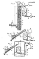
- Fig.1 shows schematically a device for rasping in vacuo agricultural products.
- the products to be rasped for example, potatoes are supplied by means of a worm conveyor 2 operating in a conduit 1 to the bottom end of a water-filled riser 3.
- an elevator 4 having perforated scoops 5 conveys the products across the water to above the manometric rising height of the water and sheds these products into a closed chute 7 leading to a rasping device 6.
- the rasping device 6 comprises a gastight housing 8 resistant to internal vacuum, in which a rasp rotor 9 is adapted to rotate. With the bottom side of the housing communicates a delivery device for the rasped pulp comprising a conduit 10 and a pump 11 included therein, which can conduct away the pulp against the atmospheric pressure and serves, in addition, as a hermetic seal.
- the riser 3, the closed chute 7 and the housing 8 constitute a system closed from the atmosphere and having a hermetic closure 12 in the part not filled with water or pulp, with which is connected an exhaust pump 13.
- the housing 8, the chute 7 and the riser 3 are exhausted by means of the exhaust pump 13, the water thus rising in the riser 3 to a height h of about 10 ms.
- the products to be rasped can be supplied through the conduit 1, the elevator and the chute 7 for being rasped in an oxygen- free manner into a gas-free pulp not exposed to oxidation. This pulp is conducted away by means of the pump 11 for being : further processed.
- F ig.2 shows a device for rasping agricultural pro- ducst in a protective gas atmosphere.
- the products are supplied to an oxygen-barring sluice in the form of a water trap 14 constituted by a reservoir 15, which communicates on the bo-tom side with an upwardly inclined pipe 16, in which a worm conveyor 17 is arranged with an amount of clearance.
- the worm conveyor 17 can conduct the products from the water-filled reservoir 15 upwards through the pipe 16 without carrying along an appreciable amount of water.
- the worm conveyor 17 terminates at a connection of the pipe 16 with a downwardly extending feeding pipe 18 leading to a rasping device 19, whose housing 20 is closed in a gastight manner, apart from the supply pipe 18, a gas supply conduit 21 and a pulp delivery conduit 23 including a pump 22.
- the penetration of oxygen is prevented by the water trap 14 in the feeding device and the pump 22 in the delivery device.
- a gas separator 25 can be arranged in the delivery conduit 23 downstream the pump.
- This embodiment is illustrated in fig.3.
- the pulp from which the gas separator has extracted the gas is conducted away through a conduit 26 and the gas is fed back through a return conduit 27 with the blower 28 to the rasping device so that the protective gas is recycled.
- Fig.3 shows moreover, a conventional rasping device 29.
- a conventional rasping device 29 In order to adapt the same to the method in accordance with the invention it is arranged in a separate gastight housing 30.
- In this housing opens out a feeding device 14 to 17 as described with reference to fig.2 and the products to be rasped are shed into a filling funnel 31 of the rasping equipment 29.
- the pulp formed by the rasping device is conducted away from a pulp collecting :trough 32 via the outlet conduit 23 including a pump 22.
- a hermetic closing member may be used as a variant comprising a riser 10 ms odd high,-in the bottom end of which opens out a feeding conduit for the products to be ground or rasped.
- the riser is provided with a conventional pump for pumping up a mixture of water and products to be ground, for example, potatoes so that at the top of the riser the mixture slightly exceeds the manometric height of the rise.
- the mixture flows over into an outlet gutter with a perforated bottom.
- the outlet gutter leads to the grinding or rasping device and beneath the perforated bottom a collecting trough is arranged and connected on the bottom side with a delivery conduit leading downwards to the bottom side of the riser. In this way the water is pumped around.
- Fig.4 is a schematic, vertical sectional view of a preferred vacuum rasping device .
- a U-shaped pipe 33 having a short limb 34 and a long limb 35 is filled with water;
- the short limb 34 which is open at the top end and which is provided with a feeding funnel 36, are introduced the products to be ground. Since the vertical distance h' between the water level in the short limb and the top side of the long limb is smaller than the hydrostatic height, which corresponds to the vacuum in the rasping device, the water in the U-shaped pipe will flow towards the top end of the long limb 35 and carry-along the products to be rasped.
- the mixture of products to be ground and water flows from the long limb 35 into a separation chamber 36 having an inclined sieve bottom 37 allowing only water to pass, which communicates with a delivery conduit 38 for passing the products to the vacuum grinding or rasping device 19.
- the products are ground or rasped'to a pulp, which is conducted away through an outlet conduit 23 including a pump 22.
- the water of the mixture flows through the sieve bottom 37 into a collecting trough 39 having a down-comer 40 in which a pump 41, for example, a centrifugal pump is arranged for pumping the fluid back to the short limb 34 of the U-shaped pipe 33.
- a pump 41 for example, a centrifugal pump is arranged for pumping the fluid back to the short limb 34 of the U-shaped pipe 33.
- a scanner 42 which is adjustable in a direction of height, for example, a float for monitoring the fluid level, said scanner being coupled with a closing member 43 in a fluid feeding conduit 44 opening out in the short limb 34.
- the pulp outlet conduits in each of the systems shown in Figs. 1 to 4 may, in accordance with the invention, be connected with a sieving device with the interposition of a buffer reservoir 50.
- the buffer reservoir is provided with a pulp inlet conduit 52.
- Through the outlet conduit 53 the pulp is pumped out of the reservoir towards the first(54) of the sequence of sieves 7.
- the sievers are preferably of the stationary type with sieve bends, in which the fluid is passed with high speed by the pump pressure over the sieve surface. Other types of sieves may also be used. After sieving the pulp is pumped towards the next sieve 56 with the aid of the pump 55.
- the fluid with any fine solid substance is pumped in a counter-flow to a preceding sieve in order to repumpt the coarser solids separated out on the sieve.
- the cell fluid is evacuated through the conduit 57 by using the pressure of the pump 58.
- a buffer 59 may be arranged between the sieving device and the conduit 57. The resultant pulp is conducted away with the aid of the pump 60 through the conduit 61.
- the sieving system is accommodated in a gas-tight housing 62 shown schematically in figure 5.
- the exhaust pump 64 maintaining said parts exhausted is connected with the housing 62 and the buffers 50 and 59.
- the pumps 58 and 60 not only serve as pumps but also as vacuum traps.
- the cell fluid is conveyed to a washing system 63, which is built up in known manner from hydrocyclones and/or centrigual devices in order to separate cell fluid, water and starch from one another. This washing system need not operate in vacuo.
- the sieving system and the associated buffers may be in an inert gas atmosphere rather than in vacuo or in atmosphere containing a reducing gas.
- each sieve with an individual gas-tight housing instaed of arranging them in common in one gas-tight housing.
- Each gas-tight housing is then connected with the exhaust pump.
Landscapes
- Chemical & Material Sciences (AREA)
- Life Sciences & Earth Sciences (AREA)
- Engineering & Computer Science (AREA)
- Biochemistry (AREA)
- Materials Engineering (AREA)
- Health & Medical Sciences (AREA)
- Chemical Kinetics & Catalysis (AREA)
- Medicinal Chemistry (AREA)
- Polymers & Plastics (AREA)
- Organic Chemistry (AREA)
- Preparation Of Fruits And Vegetables (AREA)
- Paper (AREA)
Applications Claiming Priority (2)
| Application Number | Priority Date | Filing Date | Title |
|---|---|---|---|
| JP57072490A JPS5934344B2 (ja) | 1982-04-28 | 1982-04-28 | 農産物の処理方法及び装置 |
| JP72490/82 | 1982-04-28 |
Publications (1)
| Publication Number | Publication Date |
|---|---|
| EP0092852A1 true EP0092852A1 (en) | 1983-11-02 |
Family
ID=13490811
Family Applications (1)
| Application Number | Title | Priority Date | Filing Date |
|---|---|---|---|
| EP83104185A Withdrawn EP0092852A1 (en) | 1982-04-28 | 1983-04-28 | Method and device for processing agricultural produce |
Country Status (2)
| Country | Link |
|---|---|
| EP (1) | EP0092852A1 (ja) |
| JP (1) | JPS5934344B2 (ja) |
Cited By (1)
| Publication number | Priority date | Publication date | Assignee | Title |
|---|---|---|---|---|
| GB2173993A (en) * | 1985-04-24 | 1986-10-29 | Rossi & Catelli Spa | Separating waste and processing foodstuffs |
Citations (3)
| Publication number | Priority date | Publication date | Assignee | Title |
|---|---|---|---|---|
| GB853773A (en) * | 1957-09-30 | 1960-11-09 | Corn Products Co | Starch manufacturing process |
| FR2396516A1 (fr) * | 1977-07-06 | 1979-02-02 | Beauvais Max | Appareil pour traiter en continu par le vide les produits alimentaires |
| EP0025627A1 (en) * | 1979-09-10 | 1981-03-25 | Nivoba B.V. | Method and device for grinding or rasping to pulp tubers, roots, fruit, seeds and similar agricultural produce |
-
1982
- 1982-04-28 JP JP57072490A patent/JPS5934344B2/ja not_active Expired
-
1983
- 1983-04-28 EP EP83104185A patent/EP0092852A1/en not_active Withdrawn
Patent Citations (3)
| Publication number | Priority date | Publication date | Assignee | Title |
|---|---|---|---|---|
| GB853773A (en) * | 1957-09-30 | 1960-11-09 | Corn Products Co | Starch manufacturing process |
| FR2396516A1 (fr) * | 1977-07-06 | 1979-02-02 | Beauvais Max | Appareil pour traiter en continu par le vide les produits alimentaires |
| EP0025627A1 (en) * | 1979-09-10 | 1981-03-25 | Nivoba B.V. | Method and device for grinding or rasping to pulp tubers, roots, fruit, seeds and similar agricultural produce |
Non-Patent Citations (1)
| Title |
|---|
| STARCH-STÄRKE, vol. 33, no. 1, January 1981, pages 14-17, Verlag Chemie, Weinheim, DE. * |
Cited By (1)
| Publication number | Priority date | Publication date | Assignee | Title |
|---|---|---|---|---|
| GB2173993A (en) * | 1985-04-24 | 1986-10-29 | Rossi & Catelli Spa | Separating waste and processing foodstuffs |
Also Published As
| Publication number | Publication date |
|---|---|
| JPS5934344B2 (ja) | 1984-08-22 |
| JPS58190368A (ja) | 1983-11-07 |
Similar Documents
| Publication | Publication Date | Title |
|---|---|---|
| FI58655B (fi) | Apparatur foer framstaellning av socker av hemicellulosahaltiga raoaemnen i synnerhet foer framstaellning av xylos av xylanhaltiga raoaemnen | |
| CA2409861A1 (en) | Device and method for frying products | |
| CA2277799C (en) | Closed device for treatment of drilling fluids and cuttings | |
| CA1180969A (en) | Method and apparatus for separating tobacco mixture into lighter and heavier fractions | |
| WO1989009091A1 (en) | Process and arrangement for treating recirculated drilling mud in drilling for oil and gas | |
| EA022023B1 (ru) | Способ электропорации свекловичной стружки и устройство для его осуществления | |
| EP0092852A1 (en) | Method and device for processing agricultural produce | |
| CA1335981C (en) | Method and apparatus for removal of light material from a fiber suspension | |
| EP0025627B1 (en) | Method and device for grinding or rasping to pulp tubers, roots, fruit, seeds and similar agricultural produce | |
| CA1104401A (en) | Apparatus for processing waste paper | |
| EP0251394B1 (en) | A method of separating and recovering a granulate from a viscous suspension containing said granulate, and apparatus for carrying out said method | |
| RU2101090C1 (ru) | Центробежный сепаратор | |
| CN112888506B (zh) | 分离装置和方法 | |
| US2800459A (en) | Removal of froth | |
| JP2003154205A (ja) | 油水分離装置 | |
| GB2129714A (en) | Method of and apparatus for preparing very fine coal | |
| US3237763A (en) | Method and apparatus for concentrating fibrous suspensions | |
| US3446665A (en) | Fiber recovery process | |
| US3446663A (en) | Separating device | |
| CS277395B6 (en) | Device for treating agricultural products by disintegration, crushing or grating | |
| PL140774B1 (en) | Method of separating one or more components from a pulp obtained from bulbs,roots,fruits and other agricultural products and apparatus therefor | |
| US3478875A (en) | Method and apparatus for separating nut meats from shells | |
| JPH0147227B2 (ja) | ||
| NO832933L (no) | Fremgangsmaate, samt anordning for behandling av jordbruksprodukter | |
| NL7906735A (nl) | Werkwijze en inrichting voor het tot een brij malen of raspen van knollen, wortelen, vruchten, zaden en dergelijke landbouwprodukten. |
Legal Events
| Date | Code | Title | Description |
|---|---|---|---|
| PUAI | Public reference made under article 153(3) epc to a published international application that has entered the european phase |
Free format text: ORIGINAL CODE: 0009012 |
|
| AK | Designated contracting states |
Designated state(s): AT DE FR NL SE |
|
| 17P | Request for examination filed |
Effective date: 19831224 |
|
| STAA | Information on the status of an ep patent application or granted ep patent |
Free format text: STATUS: THE APPLICATION IS DEEMED TO BE WITHDRAWN |
|
| 18D | Application deemed to be withdrawn |
Effective date: 19850626 |
|
| RIN1 | Information on inventor provided before grant (corrected) |
Inventor name: HOLTHUIS, JOHANNES JACOBUS Inventor name: KERKHOVEN, PIETER HENDRIK |