EP0092949A2 - Dispositifs de montage pour ressort à lame - Google Patents
Dispositifs de montage pour ressort à lame Download PDFInfo
- Publication number
- EP0092949A2 EP0092949A2 EP83302161A EP83302161A EP0092949A2 EP 0092949 A2 EP0092949 A2 EP 0092949A2 EP 83302161 A EP83302161 A EP 83302161A EP 83302161 A EP83302161 A EP 83302161A EP 0092949 A2 EP0092949 A2 EP 0092949A2
- Authority
- EP
- European Patent Office
- Prior art keywords
- leaf
- spring
- spring leaf
- attachment member
- end portion
- Prior art date
- Legal status (The legal status is an assumption and is not a legal conclusion. Google has not performed a legal analysis and makes no representation as to the accuracy of the status listed.)
- Granted
Links
- 230000000712 assembly Effects 0.000 title description 4
- 238000000429 assembly Methods 0.000 title description 4
- 239000002131 composite material Substances 0.000 claims abstract description 12
- 239000000463 material Substances 0.000 claims abstract description 10
- 229920003002 synthetic resin Polymers 0.000 claims abstract description 10
- 239000000057 synthetic resin Substances 0.000 claims abstract description 10
- 230000000295 complement effect Effects 0.000 claims abstract description 7
- 239000000835 fiber Substances 0.000 claims abstract description 7
- 230000001419 dependent effect Effects 0.000 claims 1
- 230000005489 elastic deformation Effects 0.000 claims 1
- 230000037431 insertion Effects 0.000 claims 1
- 238000003780 insertion Methods 0.000 claims 1
- 230000000717 retained effect Effects 0.000 abstract description 2
- 238000005553 drilling Methods 0.000 description 3
- 239000000853 adhesive Substances 0.000 description 2
- 230000001070 adhesive effect Effects 0.000 description 2
- OKTJSMMVPCPJKN-UHFFFAOYSA-N Carbon Chemical compound [C] OKTJSMMVPCPJKN-UHFFFAOYSA-N 0.000 description 1
- 229910000954 Medium-carbon steel Inorganic materials 0.000 description 1
- 239000004952 Polyamide Substances 0.000 description 1
- 229910052799 carbon Inorganic materials 0.000 description 1
- 238000005266 casting Methods 0.000 description 1
- 239000004568 cement Substances 0.000 description 1
- 238000010276 construction Methods 0.000 description 1
- 230000002939 deleterious effect Effects 0.000 description 1
- 229920006332 epoxy adhesive Polymers 0.000 description 1
- 238000005242 forging Methods 0.000 description 1
- 239000011521 glass Substances 0.000 description 1
- 238000003754 machining Methods 0.000 description 1
- 238000000465 moulding Methods 0.000 description 1
- 229920002647 polyamide Polymers 0.000 description 1
- 229920005989 resin Polymers 0.000 description 1
- 239000011347 resin Substances 0.000 description 1
- 230000003313 weakening effect Effects 0.000 description 1
Images


Classifications
-
- B—PERFORMING OPERATIONS; TRANSPORTING
- B60—VEHICLES IN GENERAL
- B60G—VEHICLE SUSPENSION ARRANGEMENTS
- B60G11/00—Resilient suspensions characterised by arrangement, location or kind of springs
- B60G11/02—Resilient suspensions characterised by arrangement, location or kind of springs having leaf springs only
- B60G11/10—Resilient suspensions characterised by arrangement, location or kind of springs having leaf springs only characterised by means specially adapted for attaching the spring to axle or sprung part of the vehicle
- B60G11/12—Links, pins, or bushes
-
- B—PERFORMING OPERATIONS; TRANSPORTING
- B60—VEHICLES IN GENERAL
- B60G—VEHICLE SUSPENSION ARRANGEMENTS
- B60G11/00—Resilient suspensions characterised by arrangement, location or kind of springs
- B60G11/02—Resilient suspensions characterised by arrangement, location or kind of springs having leaf springs only
- B60G11/10—Resilient suspensions characterised by arrangement, location or kind of springs having leaf springs only characterised by means specially adapted for attaching the spring to axle or sprung part of the vehicle
- B60G11/113—Mountings on the axle
-
- F—MECHANICAL ENGINEERING; LIGHTING; HEATING; WEAPONS; BLASTING
- F16—ENGINEERING ELEMENTS AND UNITS; GENERAL MEASURES FOR PRODUCING AND MAINTAINING EFFECTIVE FUNCTIONING OF MACHINES OR INSTALLATIONS; THERMAL INSULATION IN GENERAL
- F16F—SPRINGS; SHOCK-ABSORBERS; MEANS FOR DAMPING VIBRATION
- F16F1/00—Springs
- F16F1/36—Springs made of rubber or other material having high internal friction, e.g. thermoplastic elastomers
- F16F1/366—Springs made of rubber or other material having high internal friction, e.g. thermoplastic elastomers made of fibre-reinforced plastics, i.e. characterised by their special construction from such materials
- F16F1/368—Leaf springs
- F16F1/3683—Attachments or mountings therefor
- F16F1/3686—End mountings
Definitions
- This invention relates to leaf spring assemblies of the kind comprising a spring leaf made from a composite fibre reinforced synthetic resin material, and is more particularly concerned with the provision and securing of an attachment member to such a spring leaf whereby it may be attached to a component or structure for use.
- Such spring leaves are provided with fibres, for example of carbon or of glass, which are orientated longitudinally of the spring leaves at least in the region of the upper and lower surfaces of the leaves. They may also have fibres having a transverse or even a random orientation. If the longitudinal fibres are interrupted or broken, for example by drilling of bolt holes for securing attachment members to the spring leaves, the consequent weakening of the leaves can lead to early failure due to shear in the region of the bolt holes. It is therefore desirable to minimise any interruption of the longitudinal fibres and any shear loads applied to the spring at such interruptions.
- the present invention consists in a leaf spring assembly comprising a spring leaf of composite fibre reinforced synthetic resin material having opposed upper and lower substantially planar surfaces at an end portion thereof and an attachment member secured thereto, characterised in that the attachment member has an extension portion which is secured in intimate engagement with the end portion of the spring leaf by at least one clamping band.
- the attachment member may be an eye-end.
- the extension portion may comprise a tang, flange or the like. It is necessary for the extension portion to be of sufficient size to provide adequate support for the spring leaf to which it is secured.
- the band may be a one-piece clamping ring. After fitting of the band it may be secured to the leaf, for example by one or more pins or screws.
- One or both of the band and extension portion of the attachment member may have an inclined surface or surfaces to facilitate intimate clamping of the member and leaf in the assembly.
- the angle of the inclination is desirably between 4° and 6°, preferably between 4h l and 51 ⁇ 2°. This angle of inclination has been found to be such as to enable adequate support to be provided at the end of the spring leaf. A steeper angle increases the size and weight of the attachment member beyond what is otherwise necessary. A smaller angle presents difficulties in ensuring that when the attachment member is an eye-end the clamping band does not approach the eye too closely, detracting from the support provided by the extension portion and making it difficult to drill through the extension portion and leaf for securing the clamping band by pins or screws.
- the end portion of the spring leaf may be recessed or grooved to receive the extension portion of the attachment member.
- - Means may be provided on the attachment member adapted to locate the member relative to the leaf before clamping.
- the assembly may contain superimposed spring leaves of composite fibre reinforced synthetic resin material.
- the attachment member may be secured to the upper leaf and the, or a, band may include a support ring in which an end portion of the lower leaf is movable so as to retain location of a load applying member, for example a vehicle axle, which is connected to the leaf spring assembly, in the event of a transverse failure of the upper leaf.
- Using a band to clamp the attachment member to the spring leaf enables a small diameter pin or screw to be used to secure the assembly, thus minimising the deleterious effect on the strength of the spring leaf of piercing it to receive a securing or clamping member.
- a spring leaf 1 of composite reinforced synthetic resin material constructed in a known manner has an end portion 2 of rectangular cross-section having upper and lower surfaces 3, 4 which are flat and parallel to one another.
- An attachment member, in this case an eye-end 5, has a eye 6 adapted to receive a bolt or pin, not shown, for securing the end portion 2 of the leaf to a component or structure for use, for example a spring hanger bracket on a vehicle.
- the eye-end 5 has two flanges 7., 8 upper surfaces of which are similarly inclined downwardly at a shallow angle towards their free ends, as seen in Figure 1.
- a lower surface 9 of the eye-end is flat and the flange 8 has a depending extension 11.
- Clamping bands 12, 13 in the form of rings have machined inner surfaces within which the end portion 2 of the leaf is snugly received and have through drillings 14, 15 to receive pins 14', 15' respectively for locking the eye-end on the end portion of the leaf.
- An inner upper surface of each clamping band 12, 13 has an inclination corresponding to that of the upper surface of each of the flanges 7, 8.
- one clamping ring 12 is slid on to the spring leaf 1 and the eye-end 5 is positioned on the upper surface of the leaf with the extension 11 abutting the end face of the leaf.
- the other clamping band 13 is then applied over the end portion of the leaf and the one flange 8, and the other clamping band 12 is slid over the other flange 7.
- a load is applied between the clamping bands to draw them together and so clamp the eye-end 5 in intimate engagement with the spring leaf.
- the pre-drilled holes 14, 15 in the clamping bands are used as guides for drilling registering holes through the flanges 7, 8 and the spring leaf 1, and the locking pins 14', 15' are driven in to secure the assembly.
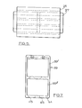
- a spring leaf 16 of composite reinforced synthetic resin material also constructed in known manner, has an end portion 23 of rectangular cross-section with flat and parallel upper and lower surfaces and is formed with a recess 17 across the end portion.
- the recess 17 is symmetrical about the longitudinal centre line of the leaf and comprises a parallel-sided portion 18 leading to an enlarged portion 19 of generally circular section.
- the recess may be formed during moulding of the spring leaf or may be machined in the leaf after it has been moulded.
- An attachment member in this case an eye-end 21, has an eye 22 adapted to receive a bolt or pin, not shown, for securing the end portion 23 of the spring leaf 16 to a component or structure for use, for example a spring hanger bracket on a vehicle.
- the eye-end 21 has a tang 24 extending radially outwards from it being complementary to the recess 17 with an enlarged free end 24' complementary to the enlarged portion 19 of the recess. As the tang 24 and recess 17 are of complementary shapes the tang is received snugly into the recess. At the root of the tang 24 the eye-end 21 has aligned shoulders 25, 26 which abut against the end face of the leaf to locate the eye-end relative to the leaf.
- a clamping band 27 in the form of a ring has its inner faces machined so as to fit snugly over the end portion 23 of the spring leaf 16 and has a hole 28 (or two spaced holes) drilled through it.
- the leaf spring assembly is constructed by sliding the clamping band 27 over the end portion of the spring leaf 16.
- the tang 24 is entered into the recess 17 from one side of the leaf until the eye-end 21 is aligned with the leaf and located relative to it by abutment of the shoulders 25, 26 against the end face of the leaf.
- the tang 24 is slightly deeper than the recess 17 and in consequence the upper and lower surfaces of the leaf are sprung apart a small amount when the tang is inserted in the recess.
- the clamping band 27 is driven towards the eye-end thereby clamping the end portion of the leaf into intimate engagement with the tang.
- a hole is then drilled through the end portion of the leaf and the tang, in register with the hole 28 in the clamping band, and a pin 28' is driven in to secure the assembly.
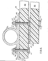
- the assembly includes a composite spring 31, only one end of which is shown, having an upper leaf 32 and a lower leaf 33 each constructed in known manner of composite reinforced synthetic resin material.
- An attachment member in the form of an eye-end 34 similar to that of Figure 1, has flanges 35, 36 upper surfaces of which are inclined downwards towards their free ends.
- One of the flanges, 35 has a downwardly depending extension 37 which abuts the end face of the leaf 32.
- the eye-end 34 is located on the end portion of the upper leaf 32 by the extension 37 and is clamped by outer and inner clamping bands 38, 39 respectively, of ring form which have inner upper surfaces inclined similarly to the inclined upper surfaces of the flanges 35, 36.
- the clamping bands 38, 39 are secured by screws 41, tapered washers 42 and lock nuts 43.
- the inner clamping band 39 has an upper ring portion 39' similar to the outer clamping band 38 which serves to clamp the one flange 36 of the eye-end 34 to the upper leaf 32 and a lower ring portion 39" in which the lower leaf 33 has freedom of movement longitudinally and vertically.
- the lower ring portion 39" has an integral bottom member 44 in which are holes 45 to enable the screws 41 in the inner clamping band 39 to be tightened.
- the lower leaf 33 has a wear plate 46, for example of polyamide, pinned to the upper surface of its end portion.
- a rubbing plate 47 for example of medium carbon steel, is secured (for example by adhesive) to the undersurface of the upper leaf 32 for rubbing engagement with the wear plate 46.
- the rubbing plate 47 could be extended to enable it to be clamped to the upper leaf 32 by the two clamping bands 38, 39 and secured by the screws 41 securing the clamping bands.
- the lower ring portion 39" of the inner band 39 which guides and supports the lower leaf 33 may alternatively comprise, as shown in Figure 8, side walls 48 and a removable closing member 49 across the bottom formed by a length of tube 50 secured between the side walls 48 by a through bolt 51, extending through holes in the side walls, and a releasing nut 52.
- a through bolt 51 extending through holes in the side walls
- a releasing nut 52 Such a construction facilitates assembly of the lower leaf to the upper leaf.
- FIG. 9 of the accompanying drawings a leaf spring assembly in accordance with the invention is shown which includes such a spring leaf.
- the assembly is generally similar to that of the first-described embodiment illustrated by Figures 1 and 2 and corresponding parts are indicated by the reference numerals used with respect to that embodiment.
- An eye-end 5 of the assembly is secured to the tapered end portion 2 of the spring leaf 1 at its flanges 7, 8 by clamping bands 12, 13 of ring form with machined inner faces retained to the flanges and leaf by pins 14', 15'.
- the flanges and clamping bands have engaging inclined surfaces.
- the lower surface 9 of the eye-end 5 seats flush on the top surface of the spring leaf.
- a wedge-shaped filling piece 53 is inserted in the clamping bands against the bottom surface of the leaf.
- the clamping bands 12, 13 act between the inclined upper surfaces of the flanges 7, 8 and the under surface 54 of the filling piece 53.
- the taper of the filling piece is such that with its upper surface lying flush against the bottom surface of the leaf its under surface 54 lies parallel to the top surface of the leaf.
- the filling piece may have an under surface which, as indicated by broken lines in Figure 9, has mutually inclined portions 55, 56 which extend to its opposite ends such that the filling piece tapers towards both of its ends.
- the inclined portions 55, 56 slope from the medial portion of the filling piece towards the inclined surfaces of the respective flanges 7, 8 of the eye-end.
- the included angles between the inclined portions 55, 56 and the inclined surfaces of the respective flanges 7, 8 are 4° to 6° and are shared between the flanges and the filling piece.
- clamping bands used to clamp the attachment members have been described as being machined on their inner surfaces. It will be understood, however, that the clamping bands may be made as precision forgings or castings to obviate machining.
- clamping bands and the flanges of the eye-ends of the assemblies of Figures 1 and 2, 6 and 9 have mutually engaging inclined surfaces, it will be appreciated that clamping may be effected with non-inclined surfaces.
- the security of the assemblies may be enhanced by the use of.an adhesive, for example an epoxy adhesive, having a resin system compatible with that of the spring leaves, to cement the lower surfaces 9 of the eye-ends to the spring leaves 1 in the embodiments of Figures 1 and 2, 6 and 9, and the tang 24 in the recess of the spring leaf 16 in the embodiment of Figures 3 to 5.
- an adhesive for example an epoxy adhesive, having a resin system compatible with that of the spring leaves, to cement the lower surfaces 9 of the eye-ends to the spring leaves 1 in the embodiments of Figures 1 and 2, 6 and 9, and the tang 24 in the recess of the spring leaf 16 in the embodiment of Figures 3 to 5.
Landscapes
- Engineering & Computer Science (AREA)
- Mechanical Engineering (AREA)
- General Engineering & Computer Science (AREA)
- Springs (AREA)
- Vehicle Body Suspensions (AREA)
Priority Applications (1)
| Application Number | Priority Date | Filing Date | Title |
|---|---|---|---|
| AT83302161T ATE28831T1 (de) | 1982-04-23 | 1983-04-18 | Blattfedermontagen. |
Applications Claiming Priority (2)
| Application Number | Priority Date | Filing Date | Title |
|---|---|---|---|
| GB8211754 | 1982-04-23 | ||
| GB8211754 | 1982-04-23 |
Publications (3)
| Publication Number | Publication Date |
|---|---|
| EP0092949A2 true EP0092949A2 (fr) | 1983-11-02 |
| EP0092949A3 EP0092949A3 (en) | 1983-12-07 |
| EP0092949B1 EP0092949B1 (fr) | 1987-08-12 |
Family
ID=10529886
Family Applications (1)
| Application Number | Title | Priority Date | Filing Date |
|---|---|---|---|
| EP83302161A Expired EP0092949B1 (fr) | 1982-04-23 | 1983-04-18 | Dispositifs de montage pour ressort à lame |
Country Status (5)
| Country | Link |
|---|---|
| US (1) | US4562998A (fr) |
| EP (1) | EP0092949B1 (fr) |
| AT (1) | ATE28831T1 (fr) |
| DE (1) | DE3372951D1 (fr) |
| GB (1) | GB2119062B (fr) |
Cited By (7)
| Publication number | Priority date | Publication date | Assignee | Title |
|---|---|---|---|---|
| WO1986002601A1 (fr) * | 1984-10-25 | 1986-05-09 | Isosport Verbundbauteile Ges.M.B.H. | Ressort a lamelles en matiere synthetique et procede pour sa fabrication |
| WO1986004864A1 (fr) * | 1985-02-21 | 1986-08-28 | Gkn Technology Limited | Assemblages de ressorts en materiau composite |
| EP0330158A3 (fr) * | 1988-02-24 | 1989-12-13 | BASF Aktiengesellschaft | Ressort à lames |
| EP0405307A1 (fr) * | 1989-06-27 | 1991-01-02 | BASF Aktiengesellschaft | Ressort à lame en matière composite renforcÀ©e par des fibres |
| EP0489304A3 (en) * | 1990-12-01 | 1992-12-02 | Basf Aktiengesellschaft | Composite leaf spring |
| FR2956713A1 (fr) * | 2010-02-24 | 2011-08-26 | Hutchinson | Lame de ressort composite a articulations pour liaison au sol de vehicule automobile, son procede de fabrication et cette liaison au sol |
| EP2905502A1 (fr) * | 2014-02-05 | 2015-08-12 | Benteler Automobiltechnik GmbH | Liaison de ressort à lame |
Families Citing this family (8)
| Publication number | Priority date | Publication date | Assignee | Title |
|---|---|---|---|---|
| AU580353B2 (en) * | 1984-10-25 | 1989-01-12 | Isosport Verbundbauteile Gesellschaft M.B.H. | Leaf spring of plastic material |
| GB2174174A (en) * | 1985-04-25 | 1986-10-29 | Gkn Technology Ltd | Securing components to leaf springs |
| GB8617538D0 (en) * | 1986-07-17 | 1986-08-28 | British Petroleum Co Plc | Leaf spring |
| US5251886A (en) * | 1992-05-14 | 1993-10-12 | Bursel Joseph S | Semi-elliptical spring suspension with automatic spring rate varying capacity |
| US9630467B2 (en) * | 2015-04-09 | 2017-04-25 | GM Global Technology Operations LLC | Leaf spring assembly |
| DE102016201965A1 (de) * | 2016-02-10 | 2017-08-10 | Zf Friedrichshafen Ag | Lagereinrichtung für eine Blattfederanordnung einer Radaufhängung |
| KR102415657B1 (ko) * | 2017-08-09 | 2022-07-04 | 현대자동차주식회사 | 복합재 리프스프링을 구비한 차량용 현가장치 |
| DE102018120288B4 (de) | 2017-08-25 | 2022-05-12 | Benteler Automobiltechnik Gmbh | Blattfederanordnung mit einer Blattfeder aus einem Faserverbundwerkstoff und wenigstens einer Lageraugenhalterung |
Family Cites Families (33)
| Publication number | Priority date | Publication date | Assignee | Title |
|---|---|---|---|---|
| US620834A (en) * | 1899-03-07 | Henry belcher and frederick easom | ||
| GB115212A (fr) * | 1900-01-01 | |||
| US1404677A (en) * | 1919-10-03 | 1922-01-24 | Larcia & C | Vehicle spring |
| US1419083A (en) * | 1920-04-08 | 1922-06-06 | Gen Motors Corp | Spring bracket |
| FR517122A (fr) * | 1920-06-14 | 1921-04-30 | Achille Leon Francois Wattel | Dispositif d'attache des ressorts de suspension pour voiture automobile |
| GB191590A (en) * | 1921-12-21 | 1923-01-18 | George Alfred Woodhead | Improvements in or relating to laminated springs for use on motor cars, automobiles and other road vehicles |
| US1436387A (en) * | 1922-01-03 | 1922-11-21 | James L Edelen | Antirattling device |
| US1544169A (en) * | 1923-03-26 | 1925-06-30 | James R Orwig | Clip bar |
| US1643232A (en) * | 1926-06-28 | 1927-09-20 | Smith Corp A O | Attaching spring hangers to the side bars of automobile frames |
| BE355262A (fr) * | 1927-07-21 | |||
| US1725266A (en) * | 1927-09-28 | 1929-08-20 | Leonard B Gump | Fastening device |
| US1814682A (en) * | 1929-04-06 | 1931-07-14 | Frost Arthur Ernest | Laminated spring |
| US1829163A (en) * | 1929-12-23 | 1931-10-27 | Us Spring And Bumper Company I | Vehicle spring construction |
| GB378137A (en) * | 1931-06-10 | 1932-08-11 | Charles Stirling | Improvements in or relating to laminated springs |
| US1931971A (en) * | 1932-04-13 | 1933-10-24 | Eaton Mfg Co | Self-locking wedge |
| US1941331A (en) * | 1933-06-01 | 1933-12-26 | Eaton Mfg Co | Vehicle spring |
| GB474995A (en) * | 1935-06-26 | 1937-11-11 | Christian Beyer | Improvements in or relating to supporting springs for motor vehicles |
| GB481425A (en) * | 1937-01-19 | 1938-03-11 | Donald Russell Martin Yates | Improvements in or relating to leaf springs |
| US2191528A (en) * | 1937-06-30 | 1940-02-27 | Frank B Hewel | Spring holder for vehicles |
| US2204940A (en) * | 1938-12-01 | 1940-06-18 | Gordon D Mainard | Leaf spring |
| DE739934C (de) * | 1941-10-21 | 1943-10-08 | Gothaer Waggonfabrik Ag | Achsstummelbefestigung an Querfedern von Fahrzeugen, insbesondere fuer Ackerwagen |
| GB627787A (en) * | 1947-05-07 | 1949-08-16 | Samuel Fox And Company Ltd | Improvements in laminated springs |
| US2670950A (en) * | 1950-07-14 | 1954-03-02 | American Steel Foundries | Spring band |
| FR1326191A (fr) * | 1962-06-22 | 1963-05-03 | Brockhouse And Company Ltd J | Perfectionnements apportés aux assemblages de ressorts |
| FR1567176A (fr) * | 1968-02-13 | 1969-05-16 | ||
| GB1192532A (en) * | 1968-05-21 | 1970-05-20 | Ford Motor Co | Leaf Spring Assembly |
| US3586307A (en) * | 1969-06-25 | 1971-06-22 | North American Rockwell | Composite spring assembly |
| US3968958A (en) * | 1972-11-30 | 1976-07-13 | Edgewater Corporation | Composite material springs and manufacture |
| GB2021731A (en) * | 1978-05-26 | 1979-12-05 | Gkn Group Services Ltd | Leaf springs of fibre-reinforced plastics |
| JPS5586934A (en) * | 1978-12-25 | 1980-07-01 | Nhk Spring Co Ltd | Frp leaf spring |
| GB2080552B (en) * | 1980-07-12 | 1984-11-21 | Rubery Owen Group Services Ltd | Measuring loads |
| EP0047074B1 (fr) * | 1980-08-30 | 1984-06-06 | GKN Group Services Limited | Ressorts stratifiés |
| DE3267900D1 (en) * | 1981-07-15 | 1986-01-23 | Gkn Technology Ltd | Leaf springs of composite material |
-
1983
- 1983-04-15 GB GB08310303A patent/GB2119062B/en not_active Expired
- 1983-04-18 DE DE8383302161T patent/DE3372951D1/de not_active Expired
- 1983-04-18 EP EP83302161A patent/EP0092949B1/fr not_active Expired
- 1983-04-18 AT AT83302161T patent/ATE28831T1/de not_active IP Right Cessation
- 1983-04-18 US US06/485,852 patent/US4562998A/en not_active Expired - Fee Related
Cited By (11)
| Publication number | Priority date | Publication date | Assignee | Title |
|---|---|---|---|---|
| WO1986002601A1 (fr) * | 1984-10-25 | 1986-05-09 | Isosport Verbundbauteile Ges.M.B.H. | Ressort a lamelles en matiere synthetique et procede pour sa fabrication |
| WO1986004864A1 (fr) * | 1985-02-21 | 1986-08-28 | Gkn Technology Limited | Assemblages de ressorts en materiau composite |
| GB2191844A (en) * | 1985-02-21 | 1987-12-23 | Gkn Technology Ltd | Assemblies of springs of composite material |
| AU570588B2 (en) * | 1985-02-21 | 1988-03-17 | Gkn Technology Limited | Assemblies of springs of composite material |
| EP0330158A3 (fr) * | 1988-02-24 | 1989-12-13 | BASF Aktiengesellschaft | Ressort à lames |
| EP0405307A1 (fr) * | 1989-06-27 | 1991-01-02 | BASF Aktiengesellschaft | Ressort à lame en matière composite renforcÀ©e par des fibres |
| EP0489304A3 (en) * | 1990-12-01 | 1992-12-02 | Basf Aktiengesellschaft | Composite leaf spring |
| FR2956713A1 (fr) * | 2010-02-24 | 2011-08-26 | Hutchinson | Lame de ressort composite a articulations pour liaison au sol de vehicule automobile, son procede de fabrication et cette liaison au sol |
| WO2011104672A1 (fr) * | 2010-02-24 | 2011-09-01 | Hutchinson | Lame de ressort composite a articulations pour liaison au sol de vehicule automobile, son procede de fabrication et cette liaison au sol |
| EP2905502A1 (fr) * | 2014-02-05 | 2015-08-12 | Benteler Automobiltechnik GmbH | Liaison de ressort à lame |
| US9370980B2 (en) | 2014-02-05 | 2016-06-21 | Benteler Automobiltechnik Gmbh | Leaf spring arrangement |
Also Published As
| Publication number | Publication date |
|---|---|
| DE3372951D1 (en) | 1987-09-17 |
| GB2119062B (en) | 1985-12-04 |
| GB2119062A (en) | 1983-11-09 |
| EP0092949A3 (en) | 1983-12-07 |
| US4562998A (en) | 1986-01-07 |
| EP0092949B1 (fr) | 1987-08-12 |
| ATE28831T1 (de) | 1987-08-15 |
| GB8310303D0 (en) | 1983-05-18 |
Similar Documents
| Publication | Publication Date | Title |
|---|---|---|
| EP0092949A2 (fr) | Dispositifs de montage pour ressort à lame | |
| US7491008B2 (en) | External fixation clamp | |
| EP0075177B1 (fr) | Outil de coupe | |
| KR890000923B1 (ko) | 압축둔부나사 | |
| CA2061018C (fr) | Mecanisme de verrouillage et barre stabilisatrice | |
| US4801129A (en) | Leaf spring clamp with attachment means | |
| WO1989011046A1 (fr) | Frein a disque a garniture partielle | |
| US6609299B2 (en) | Connecting rod | |
| WO1999048795A1 (fr) | Dispositif servant a relier un anneau de levage pivotant a une elingue plate | |
| EP3203104A1 (fr) | Fixation destinée à fixer un agrégat, en particulier une pompe, sur un véhicule automobile | |
| IE46517B1 (en) | Improvements in and relating to rail clip assemblies | |
| CA1201135A (fr) | Ressorts a lames composites | |
| US4327995A (en) | Bar pin for use in torque rods | |
| US5004019A (en) | Harness frame with detachable corner connections | |
| US4629154A (en) | Shock absorber | |
| EP0130688A1 (fr) | Le montage d'organes sur des composants ressorts de matière composite | |
| EP0240676A1 (fr) | Dispositif de fixation apte notamment au serrage central, pour un ressort à lames en matériau composite | |
| EP1052123A1 (fr) | Ensemble de fixation d'essieu et bras de suspension comprenant un tel ensemble | |
| US4289059A (en) | Hook bolt adapter | |
| IE51513B1 (en) | Composite springs | |
| US4921168A (en) | Support plate for mounting rails of railroad tracks and track switches on wooden sleepers | |
| US4343560A (en) | Spigot joint | |
| DE19524511C2 (de) | Aufhängung für Kompressoren | |
| EP0099196A1 (fr) | Ressort en matières composites | |
| CN214359725U (zh) | 一种钢结构吊装用安全夹具 |
Legal Events
| Date | Code | Title | Description |
|---|---|---|---|
| PUAI | Public reference made under article 153(3) epc to a published international application that has entered the european phase |
Free format text: ORIGINAL CODE: 0009012 |
|
| PUAL | Search report despatched |
Free format text: ORIGINAL CODE: 0009013 |
|
| AK | Designated contracting states |
Designated state(s): AT CH DE FR IT LI NL SE |
|
| AK | Designated contracting states |
Designated state(s): AT CH DE FR IT LI NL SE |
|
| 17P | Request for examination filed |
Effective date: 19840507 |
|
| GRAA | (expected) grant |
Free format text: ORIGINAL CODE: 0009210 |
|
| AK | Designated contracting states |
Kind code of ref document: B1 Designated state(s): AT CH DE FR IT LI NL SE |
|
| REF | Corresponds to: |
Ref document number: 28831 Country of ref document: AT Date of ref document: 19870815 Kind code of ref document: T |
|
| ET | Fr: translation filed | ||
| REF | Corresponds to: |
Ref document number: 3372951 Country of ref document: DE Date of ref document: 19870917 |
|
| ITF | It: translation for a ep patent filed | ||
| PLBE | No opposition filed within time limit |
Free format text: ORIGINAL CODE: 0009261 |
|
| STAA | Information on the status of an ep patent application or granted ep patent |
Free format text: STATUS: NO OPPOSITION FILED WITHIN TIME LIMIT |
|
| 26N | No opposition filed | ||
| PGFP | Annual fee paid to national office [announced via postgrant information from national office to epo] |
Ref country code: CH Payment date: 19900328 Year of fee payment: 8 |
|
| PGFP | Annual fee paid to national office [announced via postgrant information from national office to epo] |
Ref country code: FR Payment date: 19900406 Year of fee payment: 8 |
|
| PGFP | Annual fee paid to national office [announced via postgrant information from national office to epo] |
Ref country code: SE Payment date: 19900411 Year of fee payment: 8 |
|
| ITTA | It: last paid annual fee | ||
| PGFP | Annual fee paid to national office [announced via postgrant information from national office to epo] |
Ref country code: NL Payment date: 19900430 Year of fee payment: 8 Ref country code: AT Payment date: 19900430 Year of fee payment: 8 |
|
| PGFP | Annual fee paid to national office [announced via postgrant information from national office to epo] |
Ref country code: DE Payment date: 19900625 Year of fee payment: 8 |
|
| PG25 | Lapsed in a contracting state [announced via postgrant information from national office to epo] |
Ref country code: AT Effective date: 19910418 |
|
| PG25 | Lapsed in a contracting state [announced via postgrant information from national office to epo] |
Ref country code: SE Effective date: 19910419 |
|
| PG25 | Lapsed in a contracting state [announced via postgrant information from national office to epo] |
Ref country code: LI Effective date: 19910430 Ref country code: CH Effective date: 19910430 |
|
| PG25 | Lapsed in a contracting state [announced via postgrant information from national office to epo] |
Ref country code: NL Effective date: 19911101 |
|
| NLV4 | Nl: lapsed or anulled due to non-payment of the annual fee | ||
| PG25 | Lapsed in a contracting state [announced via postgrant information from national office to epo] |
Ref country code: FR Effective date: 19911230 |
|
| REG | Reference to a national code |
Ref country code: CH Ref legal event code: PL |
|
| PG25 | Lapsed in a contracting state [announced via postgrant information from national office to epo] |
Ref country code: DE Effective date: 19920201 |
|
| REG | Reference to a national code |
Ref country code: FR Ref legal event code: ST |
|
| EUG | Se: european patent has lapsed |
Ref document number: 83302161.1 Effective date: 19911108 |