EP3203104A1 - Fixation destinée à fixer un agrégat, en particulier une pompe, sur un véhicule automobile - Google Patents
Fixation destinée à fixer un agrégat, en particulier une pompe, sur un véhicule automobile Download PDFInfo
- Publication number
- EP3203104A1 EP3203104A1 EP17151583.6A EP17151583A EP3203104A1 EP 3203104 A1 EP3203104 A1 EP 3203104A1 EP 17151583 A EP17151583 A EP 17151583A EP 3203104 A1 EP3203104 A1 EP 3203104A1
- Authority
- EP
- European Patent Office
- Prior art keywords
- leg
- holder
- damping element
- fastening
- section
- Prior art date
- Legal status (The legal status is an assumption and is not a legal conclusion. Google has not performed a legal analysis and makes no representation as to the accuracy of the status listed.)
- Granted
Links
Images

Classifications
-
- B—PERFORMING OPERATIONS; TRANSPORTING
- B60—VEHICLES IN GENERAL
- B60R—VEHICLES, VEHICLE FITTINGS, OR VEHICLE PARTS, NOT OTHERWISE PROVIDED FOR
- B60R11/00—Arrangements for holding or mounting articles, not otherwise provided for
-
- F—MECHANICAL ENGINEERING; LIGHTING; HEATING; WEAPONS; BLASTING
- F16—ENGINEERING ELEMENTS AND UNITS; GENERAL MEASURES FOR PRODUCING AND MAINTAINING EFFECTIVE FUNCTIONING OF MACHINES OR INSTALLATIONS; THERMAL INSULATION IN GENERAL
- F16M—FRAMES, CASINGS OR BEDS OF ENGINES, MACHINES OR APPARATUS, NOT SPECIFIC TO ENGINES, MACHINES OR APPARATUS PROVIDED FOR ELSEWHERE; STANDS; SUPPORTS
- F16M13/00—Other supports for positioning apparatus or articles; Means for steadying hand-held apparatus or articles
- F16M13/02—Other supports for positioning apparatus or articles; Means for steadying hand-held apparatus or articles for supporting on, or attaching to, an object, e.g. tree, gate, window-frame, cycle
-
- F—MECHANICAL ENGINEERING; LIGHTING; HEATING; WEAPONS; BLASTING
- F16—ENGINEERING ELEMENTS AND UNITS; GENERAL MEASURES FOR PRODUCING AND MAINTAINING EFFECTIVE FUNCTIONING OF MACHINES OR INSTALLATIONS; THERMAL INSULATION IN GENERAL
- F16F—SPRINGS; SHOCK-ABSORBERS; MEANS FOR DAMPING VIBRATION
- F16F1/00—Springs
- F16F1/36—Springs made of rubber or other material having high internal friction, e.g. thermoplastic elastomers
- F16F1/371—Springs made of rubber or other material having high internal friction, e.g. thermoplastic elastomers characterised by inserts or auxiliary extension or exterior elements, e.g. for rigidification
-
- F—MECHANICAL ENGINEERING; LIGHTING; HEATING; WEAPONS; BLASTING
- F16—ENGINEERING ELEMENTS AND UNITS; GENERAL MEASURES FOR PRODUCING AND MAINTAINING EFFECTIVE FUNCTIONING OF MACHINES OR INSTALLATIONS; THERMAL INSULATION IN GENERAL
- F16F—SPRINGS; SHOCK-ABSORBERS; MEANS FOR DAMPING VIBRATION
- F16F15/00—Suppression of vibrations in systems; Means or arrangements for avoiding or reducing out-of-balance forces, e.g. due to motion
- F16F15/02—Suppression of vibrations of non-rotating, e.g. reciprocating systems; Suppression of vibrations of rotating systems by use of members not moving with the rotating systems
- F16F15/04—Suppression of vibrations of non-rotating, e.g. reciprocating systems; Suppression of vibrations of rotating systems by use of members not moving with the rotating systems using elastic means
-
- F—MECHANICAL ENGINEERING; LIGHTING; HEATING; WEAPONS; BLASTING
- F16—ENGINEERING ELEMENTS AND UNITS; GENERAL MEASURES FOR PRODUCING AND MAINTAINING EFFECTIVE FUNCTIONING OF MACHINES OR INSTALLATIONS; THERMAL INSULATION IN GENERAL
- F16F—SPRINGS; SHOCK-ABSORBERS; MEANS FOR DAMPING VIBRATION
- F16F15/00—Suppression of vibrations in systems; Means or arrangements for avoiding or reducing out-of-balance forces, e.g. due to motion
- F16F15/02—Suppression of vibrations of non-rotating, e.g. reciprocating systems; Suppression of vibrations of rotating systems by use of members not moving with the rotating systems
- F16F15/04—Suppression of vibrations of non-rotating, e.g. reciprocating systems; Suppression of vibrations of rotating systems by use of members not moving with the rotating systems using elastic means
- F16F15/08—Suppression of vibrations of non-rotating, e.g. reciprocating systems; Suppression of vibrations of rotating systems by use of members not moving with the rotating systems using elastic means with rubber springs ; with springs made of rubber and metal
-
- F—MECHANICAL ENGINEERING; LIGHTING; HEATING; WEAPONS; BLASTING
- F16—ENGINEERING ELEMENTS AND UNITS; GENERAL MEASURES FOR PRODUCING AND MAINTAINING EFFECTIVE FUNCTIONING OF MACHINES OR INSTALLATIONS; THERMAL INSULATION IN GENERAL
- F16M—FRAMES, CASINGS OR BEDS OF ENGINES, MACHINES OR APPARATUS, NOT SPECIFIC TO ENGINES, MACHINES OR APPARATUS PROVIDED FOR ELSEWHERE; STANDS; SUPPORTS
- F16M1/00—Frames or casings of engines, machines or apparatus; Frames serving as machinery beds
-
- H—ELECTRICITY
- H02—GENERATION; CONVERSION OR DISTRIBUTION OF ELECTRIC POWER
- H02K—DYNAMO-ELECTRIC MACHINES
- H02K5/00—Casings; Enclosures; Supports
- H02K5/04—Casings or enclosures characterised by the shape, form or construction thereof
- H02K5/16—Means for supporting bearings, e.g. insulating supports or means for fitting bearings in the bearing-shields
-
- H—ELECTRICITY
- H02—GENERATION; CONVERSION OR DISTRIBUTION OF ELECTRIC POWER
- H02K—DYNAMO-ELECTRIC MACHINES
- H02K5/00—Casings; Enclosures; Supports
- H02K5/24—Casings; Enclosures; Supports specially adapted for suppression or reduction of noise or vibrations
-
- B—PERFORMING OPERATIONS; TRANSPORTING
- B60—VEHICLES IN GENERAL
- B60R—VEHICLES, VEHICLE FITTINGS, OR VEHICLE PARTS, NOT OTHERWISE PROVIDED FOR
- B60R11/00—Arrangements for holding or mounting articles, not otherwise provided for
- B60R2011/0042—Arrangements for holding or mounting articles, not otherwise provided for characterised by mounting means
- B60R2011/0049—Arrangements for holding or mounting articles, not otherwise provided for characterised by mounting means for non integrated articles
- B60R2011/005—Connection with the vehicle part
- B60R2011/0052—Connection with the vehicle part using screws, bolts, rivets or the like
Definitions
- the invention relates to a holder according to claim 1.
- a substantially plate-shaped insert element made of metal is arranged, which is designed for local stiffening of the damping element.
- the insert is formed on two opposite edges, each with a running into the damping element wings.
- the wings have a constant thickness over their length. This leads to a different load on the insert, so that there is a risk of mechanical breakage at the transition of the wings to the plate-shaped insert.
- an improved mount for an assembly may be provided on a motor vehicle in that the mount comprises a damping element and a fastening element connected to the damping element, wherein the damping element is connectable to the aggregate, wherein the fastening element at least one leg and a connecting portion connected to the leg, wherein the leg is formed to stiffen the damping element at least partially, wherein the connection portion is connectable to the motor vehicle, wherein decreases with increasing distance to the connection portion, a thickness of the leg.
- This embodiment has the advantage that a cutting of the fastening element into a material of the damping element and a possible damage of the damping element is avoided by the fastening element.
- the thickness of the leg is at least partially selected such that when a force is introduced into the leg, a bending stress over at least a portion of the leg is constant.
- the fastening element has a further leg, wherein the further leg is connected to the connecting portion, wherein the connecting portion between the leg and the other leg is arranged.
- the damping element With increasing distance of the other leg to the connection portion takes a thickness of the other Thigh off. In this way, the damping element can be stiffened by the two legs on both sides and reliable deflection of the damping element when carrying the unit can be avoided. Furthermore, high moments are avoided on the connection portion by the simultaneous arrangement of the legs on the connection portion.
- the connecting portion, the leg and the further leg are formed integrally and of the same material.
- the fastening element preferably has a plastic, in particular a polyamide, as a material.
- the damping element has a further material, wherein the further material preferably comprises an elastomer.
- the material of the fastening element has a lower elasticity than the further material of the damping element.
- the holder is produced by means of an injection molding process, in particular a two-component injection molding process.
- the damping element is designed to extend in a ring around a longitudinal axis.
- the leg has a first section.
- the first section runs on a circular path around the longitudinal axis.
- leg comprises a second portion, wherein the second portion is formed substantially planar.
- the second portion is connected to the first portion and the attachment portion and disposed between the first portion and the attachment portion.
- the leg comprises a recess.
- the recess is preferably formed trapezoidal.
- the recess has an increasing cross section in the direction of a free end of the leg.
- the damping element has a receptacle with a receiving portion.
- the receiving portion is formed corresponding to the leg, wherein the receiving portion completely engages around the leg.
- connection section is planar.
- the leg is connected at a first side surface with the connection portion.
- the fastening element comprises a stiffening rib.
- the stiffening rib is connected to the attachment portion and preferably extends over at least 80 percent of a maximum longitudinal extent of the attachment portion. This ensures that a distortion of the connection section, in particular during curing of the connection section after injection molding, is avoided. This ensures that the connection section is flat.
- the stiffening rib is connected to the second portion of the leg.
- the stiffening rib is arranged in the transverse direction between the leg and the further leg. As a result, the holder can be made particularly compact.
- the fastening element comprises at least one fastening bolt.
- the fastening bolt is connected to the connecting portion.
- the damping element has a first contact surface and a second contact surface arranged at a distance from the first contact surface. Between the first contact surface and the second contact surface of the fastening bolt is arranged. In this way, a reliable, uniform load on the contact surface is ensured.
- the holder has an engagement element.
- the fastening bolt has a groove.
- the fastening bolt is designed to pass through a fastening section of the motor vehicle.
- the engagement element is arranged on a side facing away from the damping element of the fastening portion and engages in the groove to secure the fastening bolt on the mounting portion.
- a distance between the groove and the abutment surface is less than a thickness of the attachment portion. In this way it is ensured that the holder is non-positively connected to the mounting portion of the motor vehicle.
- the fastening element has at least one broken edge.
- the broken edge is rounded or chamfered. In this way it is ensured that the fastening element does not cut into the further material of the damping element and so early tears the damping element.
- FIG. 1 shows a perspective view of a system 10.
- the coordinate system 30 is designed as a legal system.
- the coordinate system 30 has an x-axis (longitudinal direction), a y-axis (transverse direction), and a z-axis (height).
- the x-axis, the y-axis and the z-axis intersect at an origin 31.
- the coordinate system 30 can also be designed differently.
- the coordinate system 30 is used below to explain the embodiment of the system 10 in the following figures particularly clearly.
- the system 10 includes a bracket 15, a mounting portion 20 and an assembly 25.
- the mounting portion 20 may be, for example, a part of a motor vehicle, in particular an internal combustion engine or a body.
- the unit 25 may be formed, for example, as a pump.
- the unit 25 has a cylindrical shape in sections and is connected to the fastening section 20 by means of the holder 15.
- FIG. 2 shows an exploded view of the in FIG. 1 shown system 10.
- the attachment portion 20 is exemplified plan.
- the attachment portion 20 extends, for example, in an xy plane and has, for example, a first through-opening 35 and a second through-opening 40.
- the first through-opening 35 is arranged spaced apart from the second through-opening 40 in the longitudinal direction.
- the holder 15 comprises a damping element 45 and a fastening element 50.
- the damping element 45 extends in sections annularly about a longitudinal axis 55, which is preferably aligned parallel to the x-axis, arranged in the embodiment by way of example on the x-axis is.
- the damping element 45 has a first receptacle 60.
- the first receptacle 60 is cylindrical and serves to encompass an outer circumferential surface 65 of the unit 25.
- the damping element 45 furthermore has a first contact surface 70 and preferably a second contact surface 75.
- the first abutment surface 70 and the second abutment surface 75 are arranged on a side of the damping element 45 facing the attachment section 20 and are arranged spaced apart in the transverse direction by way of example. With the first and the second contact surface 70, 75, the damping element 45 abuts against the attachment portion 20.
- the fastening section 20 has a fastening section thickness d in the z-direction.
- the damping element 45 has a depression 80.
- the depression 80 is arranged offset relative to the first and / or second contact surface 70, 75 in the z-direction on a side facing away from the attachment section 20.
- the recess 80 is formed by way of example groove-shaped.
- the fastening element 50 has, for example, a first fastening bolt 85 and a second fastening bolt 90.
- the first fastening bolt 85 is assigned to the first through-opening 35.
- the second fastening bolt 90 is assigned to the second through-opening 40.
- the fastening bolts 85, 90 each have a groove 105, 110.
- the groove 105, 110 has in the assembled state of the system 10 in the z-direction a groove spacing a to the contact surface 70, 75 on.
- the holder 15 further comprises a first engagement element 95 and, by way of example, a second engagement element 100.
- the first engagement element 95 and the second engagement element 100 are embodied identically in the embodiment by way of example.
- the engagement member 95, 100 is exemplified U-shaped.
- the engagement element 95, 100 preferably comprises metal as a material.
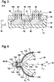
- FIG. 3 shows a cross section along an in FIG. 1 shown cutting plane AA through the system 10.
- the engagement member 95, 100 is on a for Damping element 45 facing away from the mounting portion 20 is arranged.
- the first fastening bolt 85 is guided through the first through hole 35 and the second fastening bolt 90 is guided through the second through hole 40.
- the first engagement element 95 engages in the first groove 105 and positively connects the first attachment bolt 85 with the attachment portion 20.
- the second engagement member 100 engages on a side facing away from the damping element 45 of the attachment portion 20 in the second groove 110 and positively connects the second attachment bolt 90 with the attachment portion 20th
- the engagement element 95, 100 can be pushed easily into the groove 105, 110 in the longitudinal direction, so that the holder 15 can be connected to the attachment section 20 in a particularly quick and cost-effective manner.
- the groove spacing a is smaller than the fastening section thickness d of the fastening section 20.
- the damping element 45 is compressed and prestressed on the contact surface 70, 75.
- the engagement member 95, 100 is inserted into the groove 105, 110.
- the bias is in the assembled state by the choice that the groove spacing a is smaller than the fixing portion thickness d at least partially maintained, so that the holder 15 is additionally frictionally connected to the mounting portion 20.
- tolerance compensation between bracket 15 and mounting portion 20 can be provided.
- the engagement element 95, 100 is loaded in the groove 105, 110 in the z-direction, so that unintentional release of the engagement element 95, 100 from the groove 105, 110 is prevented.
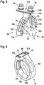
- FIG. 4 shows a side view of the fastener 50.
- the fastener 50 includes a first leg 115, a connection portion 120 and a second leg 125.
- the first leg 115 is connected at its fixed end 130 to a first side surface 135 of the attachment portion 120.
- the second leg 125 is with its fixed end 140 as well with the first side surface 135 of the Connecting portion 120 connected to the connection portion 120.
- the fixed end 130 of the first leg 115 in the transverse direction (y-axis) offset from the fixed end 140 of the second leg 125 is arranged.
- the legs 115, 125 are arranged at the same height.
- the fastening bolt 85, 90 is connected to the connection section 120.
- the attachment portion 120 is planar and exemplarily extends in an xy plane.
- the first leg 115 and the second leg 125 are formed in the embodiment, for example, to a symmetry plane 150 axisymmetric.
- the plane of symmetry 150 runs in an xy plane.
- the first leg 115 may be formed differently to the second leg 12.
- the first leg 115 has a first portion 155 and a second portion 160.
- the second section 160 adjoins the fixed end 130 of the first leg 115.
- the second section 160 is arranged between the first section 155 and the connection section 120.
- the second section 160 is planar and exemplarily extends in an xz-plane.
- the first section 155 runs on a circular path about the longitudinal axis 55.
- Other geometric configurations of the first section 155 are also conceivable.
- the first section 155 in the embodiment includes, for example, approximately a quarter-circle segment, so that a free end 165 of the first leg 115 ends approximately at the level of the longitudinal axis 55.
- a first thickness s 1 of the first leg 115 in the first section 155 decreases with increasing first distance a 1 from the connection section 120 to the free end 165 of the first leg 115.
- the first thickness s 1 is selected in the first section 155 such that when a first force F 1 acting on the first leg 115 acts in an at least partially yz-plane, for example during assembly of the unit 25 on the holder 15 first bending stress S 1 is substantially constant over the extent of the first portion 155.
- a second thickness s 2 of the second section 160 is constant, for example. Also, in the second portion 160 with increasing first distance a 1 to the connecting portion 120 toward the first portion 155 of the first leg 115, the second thickness s 2 of the first leg 115 decrease. As a result, in the second section 160, the first bending stress S 1 can be kept constant under load.
- the second leg 125 has a third section 171 and a fourth section 172.
- the fourth section 160 adjoins the fixed end 140 of the second leg 125.
- the fourth section 172 is arranged between the third section 171 and the connection section 120.
- the fourth section 172 is planar and extends transversely offset parallel to the second section 160.
- the third section 171 runs for example on a circular path about the longitudinal axis 55. Other geometric configurations of the third section 171 are conceivable.
- the third portion 171 in the embodiment includes, for example, about a quarter circle segment, wherein a free end 170 of the second leg 125 ends approximately at the level of the longitudinal axis 55. As a result, the legs 115, 125 together encompass approximately an angular segment of 180 °.
- the second and fourth sections 160, 172 have the same width in the z-direction.
- a third thickness s 3 of the second limb 125 in the third section 171 decreases with increasing second distance a 2 from the connection section 120 to the free end 170 of the second limb 125.
- the third thickness s 1 is selected in the third section 171 such that when a second force F 2 acting on the second leg 125 acts in an at least partially yz-plane, for example during assembly of the unit 25 on the holder 15, a second bending stress S 2 is substantially constant over the extension of the third portion 171.
- a fourth thickness s 4 of the fourth section 172 is constant. Also, in the fourth section 172, the fourth thickness s 4 of the second leg 125 may decrease as the second distance a 2 toward the connection section 120 increases towards the third section 171 of the second leg 125.
- the embodiment of the limb 115, 125 described above has the advantage that an expansion of the limb 115, 125 resulting from the force F 1 , F 2 and thus a resulting mechanical stress of the fastening element 50 is distributed over the entire limb 115, 125 and not locally on the legs 115, 125 acts.
- the entire structure of the fastener 50 is supporting and a predetermined breaking point is avoided on the fastener 50.
- FIG. 5 shows a perspective view of the in FIG. 4
- the first leg 115 has a first recess 175 and the second leg 125 has a second recess 180.
- the recess 175, 180 is formed by way of example trapezoidal and exemplified as a through hole in the legs 115, 125 formed. It would also be conceivable that the recess is formed as a recess in the legs 115, 125 and / or only one of the two legs 115, 125 has the recess 175, 180. Also can be dispensed with the recess 175, 180.
- the recess 175, 180 has in the direction of the free end 165, 170 of the leg 115, 125 an increasing cross-section.
- the recess 175, 180 may be geometrically different.
- the first recess 175 and the first section 155 of the first leg 115 are matched to one another such that when the first force F 1 is introduced into the first section 155, the first bending stress S 1 is constant over the extent of the first section 155.
- the second recess 180 and the third section 171 of the second leg 125 are advantageously matched to one another such that when the second force F 2 is introduced into the third section 171, the second bending stress S 2 is constant over the extent of the third section 171.
- the connecting portion 120, the first leg 115, the second leg 125 and the fastening bolt 85, 90 are formed in one piece and of uniform material. Particularly advantageous here is when the fastener 50 has a plastic, in particular a polyamide, as a material. Furthermore, it is advantageous if the fastening element 50 is produced by means of an injection molding process.
- At least one edge 173 of the fastener 50 preferably all the edges 173, are broken.
- the broken edge 173 may be rounded or chamfered.
- FIG. 6 shows a perspective view of the damping element 45.
- the damping element 45 is formed substantially annular and has a second receptacle 185.
- the second receptacle 185 has a first receiving portion 190, a second receiving portion 195 and a third receiving portion 200.
- the second receptacle 185 comprises a first outlet opening 205 and a second outlet opening 210.
- the first outlet opening 205 and the second outlet opening 210 are arranged adjacent to the depression 80 between the two contact surfaces 70, 75.
- the outlet opening 205, 210 is connected to the second receiving portion 195.
- first receiving portion 190 of the first leg 115 engages.
- first leg 115 in the first receiving portion 190 is completely encompassed by the first receiving portion 190, so that the first leg 115 is completely covered by a further material of the damping element 45.
- second receiving portion 195 of the connecting portion 120 engages.
- the second receiving section 195 completely surrounds the connecting section 120.
- the first fastening opening 205 carries the first fastening bolt 85 and the second fastening opening 90 guides the second fastening bolt 90.
- the third receiving portion 200 of the second leg engages 125, wherein the third receiving portion 200 completely surrounds the second leg 125, so that the second leg 125 is completely surrounded by the further material of the damping element 45.
- the holder 15 is produced by means of a two-component injection molding process. It is also conceivable that the fastening element 50 is produced in a first injection molding process and serves as a depositor in a second injection molding process, in which the fastening element 50 is encapsulated with the further material of the damping element 45. As a result, the holder 15 can be produced particularly inexpensively and easily. In particular, can be dispensed with a time-intensive use of a primer on the fastener 50 for cohesive connection of the fastener 50 with the damping element 45.
- EPDM ethylene-propylene-diene rubber
- the material of the fastener 50 has a lower elasticity than the other material of the damping element 45. This ensures that vibrations between the unit 25 and the mounting portion 20 are effectively damped by the damping element 45 and not on the bracket 15 between the Attachment section 20 and the unit 25 are transmitted. In this way, it is ensured that the unit 25 is mounted with low vibration and, on the other hand, that vibrations generated by the unit 25 are not transmitted to the attachment section 20.
- the broken edge 173 on the fastening element 50 further ensures that the fastening element 50 does not locally overstress the material of the damping element 45 and thereby tears the further material of the damping element 45.
- the recess 175, 180 ensures that the introduced during assembly of the unit 25 on the holder in the holder 15 stretching of the fastener 50 does not act locally, but the strain on the entire leg 115, 125 is distributed. This increases the load capacity of the Further, the recess 175, 180 provides a positive connection with the damping element 45 and thus reduces a shear stress on common surfaces between legs 115, 125 and damping element 45th
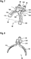
- FIG. 7 shows a perspective view of a development of the in the FIGS. 4 and 5
- the fastener 50 illustratively includes a first stiffening rib 215 and, for example, a second stiffening rib 220.
- the stiffening rib 215, 220 is disposed on the first side surface 135 of the attachment portion 120.
- the stiffening rib 215, 220 extends in the longitudinal direction (x-axis), for example, parallel to the longitudinal axis 55.
- the first stiffening rib 215 is connected to the second portion 160 of the first leg 115.
- the second stiffening rib 220 is longitudinally connected to the second portion 160 of the second leg 125.
- the reinforcing rib 215, 220 extends over at least 80 percent of a maximum longitudinal extent I of the connecting portion 120.
- This embodiment has the advantage that a moment of resistance of the connection section 120 is increased and so that the connection section 120 remains distortion-free and flat even under mechanical load. This prevents a bending of the connection portion 120 out of the plane, for example, due to thermal stresses during injection molding of the fastener 50 is avoided. This ensures that the first fastening bolt 85 is aligned parallel to the second fastening bolt 90 in the z-direction.
- FIG. 8 shows a perspective view of a development of in FIG. 7 illustrated fastener 50.
- the stiffening rib 215 is in the transverse direction is disposed between the first leg 115 and the second leg 125 and extends substantially over the entire longitudinal extent of the attachment portion 120th
- FIGS. 1 to 8 shown features can be combined with each other and / or can be dispensed with individual features.
Landscapes
- Engineering & Computer Science (AREA)
- General Engineering & Computer Science (AREA)
- Mechanical Engineering (AREA)
- Power Engineering (AREA)
- Physics & Mathematics (AREA)
- Acoustics & Sound (AREA)
- Aviation & Aerospace Engineering (AREA)
- Chemical & Material Sciences (AREA)
- Combustion & Propulsion (AREA)
- Vibration Prevention Devices (AREA)
- Clamps And Clips (AREA)
- Springs (AREA)
Applications Claiming Priority (1)
| Application Number | Priority Date | Filing Date | Title |
|---|---|---|---|
| DE102016201560.5A DE102016201560B4 (de) | 2016-02-02 | 2016-02-02 | Halterung zur Befestigung eines Aggregats, insbesondere einer Pumpe, an einem Kraftfahrzeug |
Publications (2)
| Publication Number | Publication Date |
|---|---|
| EP3203104A1 true EP3203104A1 (fr) | 2017-08-09 |
| EP3203104B1 EP3203104B1 (fr) | 2021-12-08 |
Family
ID=57821852
Family Applications (1)
| Application Number | Title | Priority Date | Filing Date |
|---|---|---|---|
| EP17151583.6A Active EP3203104B1 (fr) | 2016-02-02 | 2017-01-16 | Fixation destinée à fixer un agrégat, en particulier une pompe, sur un véhicule automobile |
Country Status (5)
| Country | Link |
|---|---|
| US (1) | US9994161B2 (fr) |
| EP (1) | EP3203104B1 (fr) |
| JP (1) | JP6851209B2 (fr) |
| CN (1) | CN107131412B (fr) |
| DE (1) | DE102016201560B4 (fr) |
Cited By (1)
| Publication number | Priority date | Publication date | Assignee | Title |
|---|---|---|---|---|
| FR3119568A1 (fr) * | 2021-02-11 | 2022-08-12 | Psa Automobiles Sa | Ensemble a support de pompe et ecran thermique pour un moteur thermique |
Families Citing this family (7)
| Publication number | Priority date | Publication date | Assignee | Title |
|---|---|---|---|---|
| DE102016209204A1 (de) * | 2016-05-27 | 2017-11-30 | Robert Bosch Gmbh | Vorrichtung zur Regelung mindestens eines Fluidstroms in einem Fahrzeug |
| US10131222B1 (en) * | 2017-05-05 | 2018-11-20 | Toyota Motor Engineering & Manufacturing North America, Inc. | Snorkel roof drip attachment |
| JP6499734B2 (ja) | 2017-08-24 | 2019-04-10 | ファナック株式会社 | 取付構造および冷却ファン |
| EP3785961B1 (fr) * | 2019-08-26 | 2025-10-15 | Vibracoustic Nantes SAS | Support pour soutenir un moteur électrique et procédé de fabrication d'un tel support |
| US12184152B1 (en) * | 2021-01-11 | 2024-12-31 | Hydro-Gear Limited Partnership | Vibration damping apparatus for mounting an electric actuator on a hydraulic drive |
| DE102021106098B3 (de) * | 2021-03-12 | 2022-05-25 | Bühler Motor GmbH | Halterung zur Befestigung einer Pumpe |
| US20250163938A1 (en) * | 2022-04-04 | 2025-05-22 | Aisin Corporation | Electric pump |
Citations (3)
| Publication number | Priority date | Publication date | Assignee | Title |
|---|---|---|---|---|
| DE2526061A1 (de) * | 1974-06-13 | 1975-12-18 | Pneumatiques Caoutchouc Mfg | Stossdaempfer fuer fender |
| JPS62274123A (ja) * | 1986-05-21 | 1987-11-28 | Suzuki Motor Co Ltd | 弾性支持体 |
| DE102011085558A1 (de) | 2011-11-02 | 2013-05-02 | Robert Bosch Gmbh | Halterung zur Befestigung eines Aggregats, insbesondere einer Pumpe, an einem Kraftfahrzeug |
Family Cites Families (20)
| Publication number | Priority date | Publication date | Assignee | Title |
|---|---|---|---|---|
| US3012743A (en) * | 1959-10-05 | 1961-12-12 | Jenkins Orville | Motor mounting ring |
| DE2933586C2 (de) | 1979-08-18 | 1982-11-18 | Goetze Ag, 5093 Burscheid | Schwingungstilger für rotierende Wellen |
| SE467635B (sv) | 1988-09-30 | 1992-08-17 | Electrolux Ab | Vibrationsdaempare i motorsaag |
| JPH051666Y2 (fr) * | 1989-02-20 | 1993-01-18 | ||
| US5113104A (en) * | 1989-10-19 | 1992-05-12 | General Electric Company | Structured product dynamoelectric machine |
| US5397950A (en) * | 1993-12-23 | 1995-03-14 | Cary Products Co., Inc. | Isolation motor mount and gasket |
| ES2115114T3 (es) * | 1994-08-08 | 1998-06-16 | Siemens Ag | Dispositivo de fijacion insonorizante para motores, especialmente para accionamientos reguladores electricos en vehiculos motorizados. |
| DE19713461C2 (de) | 1996-03-20 | 1999-02-11 | Henniges Elastomer Kunststoff | Elastomeres Federelement |
| JPH11241744A (ja) * | 1998-02-26 | 1999-09-07 | Mitsubishi Eng Plast Corp | 樹脂製ばね及び樹脂製ばね組立体 |
| JP2002181101A (ja) * | 2000-12-18 | 2002-06-26 | Maruyasu Industries Co Ltd | ブラケットリング |
| JP2004242478A (ja) * | 2003-02-10 | 2004-08-26 | Nippon Pop Rivets & Fasteners Ltd | ケーブルクランプ |
| US20050023912A1 (en) * | 2003-07-28 | 2005-02-03 | A.O. Smith Corporation | Electric motor for hydromassage bathtubs |
| DE202004017501U1 (de) * | 2004-11-11 | 2005-01-05 | Kirchhoff Gmbh & Co.Kg | Vorrichtung zur Verbindung zweier Abgas führender Rohre |
| US20070035073A1 (en) * | 2005-08-10 | 2007-02-15 | Kinmartin Jeffrey C | Isolation for electric motor |
| JP5074935B2 (ja) * | 2008-01-21 | 2012-11-14 | 日本電産セイミツ株式会社 | 振動モータ |
| DE102009029067A1 (de) * | 2009-09-01 | 2011-03-03 | Robert Bosch Gmbh | Halterung zur Befestigung eines Aggregats |
| US8714943B2 (en) * | 2010-09-29 | 2014-05-06 | Halla Visteon Climate Control Corporation | Mounting and damping system for a compressor |
| JP5836781B2 (ja) * | 2011-12-06 | 2015-12-24 | 株式会社ブリヂストン | 防振装置 |
| JP5967800B2 (ja) * | 2012-01-31 | 2016-08-10 | ミネベア株式会社 | フレキシブルプリント基板のホルダを備えるモータ及びそのモータを用いたアクチュエータ |
| KR101339261B1 (ko) * | 2012-10-16 | 2013-12-09 | 기아자동차 주식회사 | 차량용 트랜스미션 마운팅 유닛 |
-
2016
- 2016-02-02 DE DE102016201560.5A patent/DE102016201560B4/de not_active Expired - Fee Related
- 2016-05-26 US US15/165,229 patent/US9994161B2/en active Active
-
2017
- 2017-01-16 EP EP17151583.6A patent/EP3203104B1/fr active Active
- 2017-01-26 CN CN201710349987.1A patent/CN107131412B/zh active Active
- 2017-02-02 JP JP2017017573A patent/JP6851209B2/ja active Active
Patent Citations (3)
| Publication number | Priority date | Publication date | Assignee | Title |
|---|---|---|---|---|
| DE2526061A1 (de) * | 1974-06-13 | 1975-12-18 | Pneumatiques Caoutchouc Mfg | Stossdaempfer fuer fender |
| JPS62274123A (ja) * | 1986-05-21 | 1987-11-28 | Suzuki Motor Co Ltd | 弾性支持体 |
| DE102011085558A1 (de) | 2011-11-02 | 2013-05-02 | Robert Bosch Gmbh | Halterung zur Befestigung eines Aggregats, insbesondere einer Pumpe, an einem Kraftfahrzeug |
Cited By (2)
| Publication number | Priority date | Publication date | Assignee | Title |
|---|---|---|---|---|
| FR3119568A1 (fr) * | 2021-02-11 | 2022-08-12 | Psa Automobiles Sa | Ensemble a support de pompe et ecran thermique pour un moteur thermique |
| WO2022171939A1 (fr) * | 2021-02-11 | 2022-08-18 | Psa Automobiles Sa | Ensemble a support de pompe et ecran thermique pour un moteur thermique |
Also Published As
| Publication number | Publication date |
|---|---|
| EP3203104B1 (fr) | 2021-12-08 |
| US9994161B2 (en) | 2018-06-12 |
| JP2017161068A (ja) | 2017-09-14 |
| CN107131412A (zh) | 2017-09-05 |
| US20170217380A1 (en) | 2017-08-03 |
| DE102016201560A1 (de) | 2017-08-03 |
| JP6851209B2 (ja) | 2021-03-31 |
| CN107131412B (zh) | 2021-08-03 |
| DE102016201560B4 (de) | 2024-02-01 |
Similar Documents
| Publication | Publication Date | Title |
|---|---|---|
| EP3203104B1 (fr) | Fixation destinée à fixer un agrégat, en particulier une pompe, sur un véhicule automobile | |
| EP1729387A2 (fr) | Dispositif de fixation d'une ligne | |
| DE102012024653B4 (de) | Entkopplungselement | |
| EP2473755B1 (fr) | Système d'attache pour la fixation d'un groupe | |
| DE102007017991B4 (de) | Blattfeder aus einem Faser-Kunststoff-Verbundwerkstoff und Krafteinleitungselement für dieselbe | |
| DE69918969T2 (de) | Motorlager | |
| EP2251579B1 (fr) | Collier de serrage | |
| DE102009028458B4 (de) | Modulares Lenkerelement | |
| DE102016012538A1 (de) | Gummilager und Verfahren zum Herstellen eines Gummilagers | |
| DE102016200307A1 (de) | Federteller für einen Schwingungsdämpfer | |
| EP2985164A1 (fr) | Support de moteur | |
| EP1375293A2 (fr) | Dispositif d'accouplement élastique entre éléments structuraux soumis aux vibrations | |
| DE3937339C2 (de) | Befestigungselement und Verfahren zu dessen Herstellung | |
| DE102016118138B4 (de) | Toleranzausgleichselement zum Ausgleichen eines Abstandes zwischen einem Instrumententräger und einem Karosseriebauteil eines Fahrzeugs | |
| EP3682098B1 (fr) | Dispositif de retenue | |
| EP0762012B1 (fr) | Amortisseur dynamique | |
| DE102019008388A1 (de) | Lagersystem und Verfahren zur Lagerung eines Fahrzeugbauteils | |
| EP2323871B1 (fr) | Système d'airbag | |
| DE102010006279B4 (de) | Anordnung an einem Fahrzeugaufbau zur Befestigung eines Schwingungsdämpfers oder eines Federbeins | |
| EP1609703A2 (fr) | Poutre transversale | |
| DE102023207479A1 (de) | Vorrichtung zum Ausgleichen von Toleranzen | |
| DE102004001286B4 (de) | Vorrichtung zur Halterung eines Bauteils an einer Karosserie | |
| DE102012023785A1 (de) | Vorrichtung zum spannungsarmen Verbinden zweier Bauteile eines Kraftfahrzeuges sowie Fahrzeug-Scheinwerfer | |
| EP2009258A2 (fr) | Support rigide pour une suspension d'une installation de gaz d'échappement d'un véhicule automobile | |
| DE10325433B4 (de) | Airbaggehäuse |
Legal Events
| Date | Code | Title | Description |
|---|---|---|---|
| PUAI | Public reference made under article 153(3) epc to a published international application that has entered the european phase |
Free format text: ORIGINAL CODE: 0009012 |
|
| STAA | Information on the status of an ep patent application or granted ep patent |
Free format text: STATUS: THE APPLICATION HAS BEEN PUBLISHED |
|
| AK | Designated contracting states |
Kind code of ref document: A1 Designated state(s): AL AT BE BG CH CY CZ DE DK EE ES FI FR GB GR HR HU IE IS IT LI LT LU LV MC MK MT NL NO PL PT RO RS SE SI SK SM TR |
|
| AX | Request for extension of the european patent |
Extension state: BA ME |
|
| STAA | Information on the status of an ep patent application or granted ep patent |
Free format text: STATUS: REQUEST FOR EXAMINATION WAS MADE |
|
| 17P | Request for examination filed |
Effective date: 20180209 |
|
| RBV | Designated contracting states (corrected) |
Designated state(s): AL AT BE BG CH CY CZ DE DK EE ES FI FR GB GR HR HU IE IS IT LI LT LU LV MC MK MT NL NO PL PT RO RS SE SI SK SM TR |
|
| RAP1 | Party data changed (applicant data changed or rights of an application transferred) |
Owner name: ROBERT BOSCH GMBH |
|
| GRAP | Despatch of communication of intention to grant a patent |
Free format text: ORIGINAL CODE: EPIDOSNIGR1 |
|
| STAA | Information on the status of an ep patent application or granted ep patent |
Free format text: STATUS: GRANT OF PATENT IS INTENDED |
|
| INTG | Intention to grant announced |
Effective date: 20210706 |
|
| GRAS | Grant fee paid |
Free format text: ORIGINAL CODE: EPIDOSNIGR3 |
|
| GRAA | (expected) grant |
Free format text: ORIGINAL CODE: 0009210 |
|
| STAA | Information on the status of an ep patent application or granted ep patent |
Free format text: STATUS: THE PATENT HAS BEEN GRANTED |
|
| AK | Designated contracting states |
Kind code of ref document: B1 Designated state(s): AL AT BE BG CH CY CZ DE DK EE ES FI FR GB GR HR HU IE IS IT LI LT LU LV MC MK MT NL NO PL PT RO RS SE SI SK SM TR |
|
| REG | Reference to a national code |
Ref country code: GB Ref legal event code: FG4D Free format text: NOT ENGLISH |
|
| REG | Reference to a national code |
Ref country code: AT Ref legal event code: REF Ref document number: 1454010 Country of ref document: AT Kind code of ref document: T Effective date: 20211215 Ref country code: CH Ref legal event code: EP |
|
| REG | Reference to a national code |
Ref country code: DE Ref legal event code: R096 Ref document number: 502017012169 Country of ref document: DE |
|
| REG | Reference to a national code |
Ref country code: IE Ref legal event code: FG4D Free format text: LANGUAGE OF EP DOCUMENT: GERMAN |
|
| REG | Reference to a national code |
Ref country code: LT Ref legal event code: MG9D |
|
| REG | Reference to a national code |
Ref country code: NL Ref legal event code: MP Effective date: 20211208 |
|
| PG25 | Lapsed in a contracting state [announced via postgrant information from national office to epo] |
Ref country code: RS Free format text: LAPSE BECAUSE OF FAILURE TO SUBMIT A TRANSLATION OF THE DESCRIPTION OR TO PAY THE FEE WITHIN THE PRESCRIBED TIME-LIMIT Effective date: 20211208 Ref country code: LT Free format text: LAPSE BECAUSE OF FAILURE TO SUBMIT A TRANSLATION OF THE DESCRIPTION OR TO PAY THE FEE WITHIN THE PRESCRIBED TIME-LIMIT Effective date: 20211208 Ref country code: FI Free format text: LAPSE BECAUSE OF FAILURE TO SUBMIT A TRANSLATION OF THE DESCRIPTION OR TO PAY THE FEE WITHIN THE PRESCRIBED TIME-LIMIT Effective date: 20211208 Ref country code: BG Free format text: LAPSE BECAUSE OF FAILURE TO SUBMIT A TRANSLATION OF THE DESCRIPTION OR TO PAY THE FEE WITHIN THE PRESCRIBED TIME-LIMIT Effective date: 20220308 |
|
| PG25 | Lapsed in a contracting state [announced via postgrant information from national office to epo] |
Ref country code: SE Free format text: LAPSE BECAUSE OF FAILURE TO SUBMIT A TRANSLATION OF THE DESCRIPTION OR TO PAY THE FEE WITHIN THE PRESCRIBED TIME-LIMIT Effective date: 20211208 Ref country code: NO Free format text: LAPSE BECAUSE OF FAILURE TO SUBMIT A TRANSLATION OF THE DESCRIPTION OR TO PAY THE FEE WITHIN THE PRESCRIBED TIME-LIMIT Effective date: 20220308 Ref country code: LV Free format text: LAPSE BECAUSE OF FAILURE TO SUBMIT A TRANSLATION OF THE DESCRIPTION OR TO PAY THE FEE WITHIN THE PRESCRIBED TIME-LIMIT Effective date: 20211208 Ref country code: HR Free format text: LAPSE BECAUSE OF FAILURE TO SUBMIT A TRANSLATION OF THE DESCRIPTION OR TO PAY THE FEE WITHIN THE PRESCRIBED TIME-LIMIT Effective date: 20211208 Ref country code: GR Free format text: LAPSE BECAUSE OF FAILURE TO SUBMIT A TRANSLATION OF THE DESCRIPTION OR TO PAY THE FEE WITHIN THE PRESCRIBED TIME-LIMIT Effective date: 20220309 Ref country code: ES Free format text: LAPSE BECAUSE OF FAILURE TO SUBMIT A TRANSLATION OF THE DESCRIPTION OR TO PAY THE FEE WITHIN THE PRESCRIBED TIME-LIMIT Effective date: 20211208 |
|
| PG25 | Lapsed in a contracting state [announced via postgrant information from national office to epo] |
Ref country code: NL Free format text: LAPSE BECAUSE OF FAILURE TO SUBMIT A TRANSLATION OF THE DESCRIPTION OR TO PAY THE FEE WITHIN THE PRESCRIBED TIME-LIMIT Effective date: 20211208 |
|
| PG25 | Lapsed in a contracting state [announced via postgrant information from national office to epo] |
Ref country code: SM Free format text: LAPSE BECAUSE OF FAILURE TO SUBMIT A TRANSLATION OF THE DESCRIPTION OR TO PAY THE FEE WITHIN THE PRESCRIBED TIME-LIMIT Effective date: 20211208 Ref country code: SK Free format text: LAPSE BECAUSE OF FAILURE TO SUBMIT A TRANSLATION OF THE DESCRIPTION OR TO PAY THE FEE WITHIN THE PRESCRIBED TIME-LIMIT Effective date: 20211208 Ref country code: RO Free format text: LAPSE BECAUSE OF FAILURE TO SUBMIT A TRANSLATION OF THE DESCRIPTION OR TO PAY THE FEE WITHIN THE PRESCRIBED TIME-LIMIT Effective date: 20211208 Ref country code: PT Free format text: LAPSE BECAUSE OF FAILURE TO SUBMIT A TRANSLATION OF THE DESCRIPTION OR TO PAY THE FEE WITHIN THE PRESCRIBED TIME-LIMIT Effective date: 20220408 Ref country code: EE Free format text: LAPSE BECAUSE OF FAILURE TO SUBMIT A TRANSLATION OF THE DESCRIPTION OR TO PAY THE FEE WITHIN THE PRESCRIBED TIME-LIMIT Effective date: 20211208 |
|
| PG25 | Lapsed in a contracting state [announced via postgrant information from national office to epo] |
Ref country code: PL Free format text: LAPSE BECAUSE OF FAILURE TO SUBMIT A TRANSLATION OF THE DESCRIPTION OR TO PAY THE FEE WITHIN THE PRESCRIBED TIME-LIMIT Effective date: 20211208 |
|
| REG | Reference to a national code |
Ref country code: CH Ref legal event code: PL |
|
| REG | Reference to a national code |
Ref country code: DE Ref legal event code: R097 Ref document number: 502017012169 Country of ref document: DE |
|
| PG25 | Lapsed in a contracting state [announced via postgrant information from national office to epo] |
Ref country code: MC Free format text: LAPSE BECAUSE OF FAILURE TO SUBMIT A TRANSLATION OF THE DESCRIPTION OR TO PAY THE FEE WITHIN THE PRESCRIBED TIME-LIMIT Effective date: 20211208 Ref country code: IS Free format text: LAPSE BECAUSE OF FAILURE TO SUBMIT A TRANSLATION OF THE DESCRIPTION OR TO PAY THE FEE WITHIN THE PRESCRIBED TIME-LIMIT Effective date: 20220408 |
|
| REG | Reference to a national code |
Ref country code: BE Ref legal event code: MM Effective date: 20220131 |
|
| PLBE | No opposition filed within time limit |
Free format text: ORIGINAL CODE: 0009261 |
|
| STAA | Information on the status of an ep patent application or granted ep patent |
Free format text: STATUS: NO OPPOSITION FILED WITHIN TIME LIMIT |
|
| PG25 | Lapsed in a contracting state [announced via postgrant information from national office to epo] |
Ref country code: LU Free format text: LAPSE BECAUSE OF NON-PAYMENT OF DUE FEES Effective date: 20220116 Ref country code: DK Free format text: LAPSE BECAUSE OF FAILURE TO SUBMIT A TRANSLATION OF THE DESCRIPTION OR TO PAY THE FEE WITHIN THE PRESCRIBED TIME-LIMIT Effective date: 20211208 Ref country code: AL Free format text: LAPSE BECAUSE OF FAILURE TO SUBMIT A TRANSLATION OF THE DESCRIPTION OR TO PAY THE FEE WITHIN THE PRESCRIBED TIME-LIMIT Effective date: 20211208 |
|
| 26N | No opposition filed |
Effective date: 20220909 |
|
| GBPC | Gb: european patent ceased through non-payment of renewal fee |
Effective date: 20220308 |
|
| PG25 | Lapsed in a contracting state [announced via postgrant information from national office to epo] |
Ref country code: SI Free format text: LAPSE BECAUSE OF FAILURE TO SUBMIT A TRANSLATION OF THE DESCRIPTION OR TO PAY THE FEE WITHIN THE PRESCRIBED TIME-LIMIT Effective date: 20211208 Ref country code: BE Free format text: LAPSE BECAUSE OF NON-PAYMENT OF DUE FEES Effective date: 20220131 |
|
| PG25 | Lapsed in a contracting state [announced via postgrant information from national office to epo] |
Ref country code: LI Free format text: LAPSE BECAUSE OF NON-PAYMENT OF DUE FEES Effective date: 20220131 Ref country code: FR Free format text: LAPSE BECAUSE OF NON-PAYMENT OF DUE FEES Effective date: 20220208 Ref country code: CH Free format text: LAPSE BECAUSE OF NON-PAYMENT OF DUE FEES Effective date: 20220131 |
|
| PG25 | Lapsed in a contracting state [announced via postgrant information from national office to epo] |
Ref country code: IE Free format text: LAPSE BECAUSE OF NON-PAYMENT OF DUE FEES Effective date: 20220116 Ref country code: GB Free format text: LAPSE BECAUSE OF NON-PAYMENT OF DUE FEES Effective date: 20220308 |
|
| REG | Reference to a national code |
Ref country code: AT Ref legal event code: MM01 Ref document number: 1454010 Country of ref document: AT Kind code of ref document: T Effective date: 20220116 |
|
| PG25 | Lapsed in a contracting state [announced via postgrant information from national office to epo] |
Ref country code: AT Free format text: LAPSE BECAUSE OF NON-PAYMENT OF DUE FEES Effective date: 20220116 |
|
| PG25 | Lapsed in a contracting state [announced via postgrant information from national office to epo] |
Ref country code: HU Free format text: LAPSE BECAUSE OF FAILURE TO SUBMIT A TRANSLATION OF THE DESCRIPTION OR TO PAY THE FEE WITHIN THE PRESCRIBED TIME-LIMIT; INVALID AB INITIO Effective date: 20170116 |
|
| PG25 | Lapsed in a contracting state [announced via postgrant information from national office to epo] |
Ref country code: MK Free format text: LAPSE BECAUSE OF FAILURE TO SUBMIT A TRANSLATION OF THE DESCRIPTION OR TO PAY THE FEE WITHIN THE PRESCRIBED TIME-LIMIT Effective date: 20211208 Ref country code: CY Free format text: LAPSE BECAUSE OF FAILURE TO SUBMIT A TRANSLATION OF THE DESCRIPTION OR TO PAY THE FEE WITHIN THE PRESCRIBED TIME-LIMIT Effective date: 20211208 |
|
| PG25 | Lapsed in a contracting state [announced via postgrant information from national office to epo] |
Ref country code: TR Free format text: LAPSE BECAUSE OF FAILURE TO SUBMIT A TRANSLATION OF THE DESCRIPTION OR TO PAY THE FEE WITHIN THE PRESCRIBED TIME-LIMIT Effective date: 20211208 |
|
| PG25 | Lapsed in a contracting state [announced via postgrant information from national office to epo] |
Ref country code: MT Free format text: LAPSE BECAUSE OF FAILURE TO SUBMIT A TRANSLATION OF THE DESCRIPTION OR TO PAY THE FEE WITHIN THE PRESCRIBED TIME-LIMIT Effective date: 20211208 |
|
| PGFP | Annual fee paid to national office [announced via postgrant information from national office to epo] |
Ref country code: DE Payment date: 20260319 Year of fee payment: 10 |
|
| PGFP | Annual fee paid to national office [announced via postgrant information from national office to epo] |
Ref country code: IT Payment date: 20260130 Year of fee payment: 10 |
|
| PGFP | Annual fee paid to national office [announced via postgrant information from national office to epo] |
Ref country code: CZ Payment date: 20260102 Year of fee payment: 10 |