EP0199687A1 - Colonne de direction réglable pour véhicules - Google Patents
Colonne de direction réglable pour véhicules Download PDFInfo
- Publication number
- EP0199687A1 EP0199687A1 EP86850080A EP86850080A EP0199687A1 EP 0199687 A1 EP0199687 A1 EP 0199687A1 EP 86850080 A EP86850080 A EP 86850080A EP 86850080 A EP86850080 A EP 86850080A EP 0199687 A1 EP0199687 A1 EP 0199687A1
- Authority
- EP
- European Patent Office
- Prior art keywords
- piston
- steering wheel
- wheel shaft
- housing
- steering column
- Prior art date
- Legal status (The legal status is an assumption and is not a legal conclusion. Google has not performed a legal analysis and makes no representation as to the accuracy of the status listed.)
- Granted
Links
- 238000006073 displacement reaction Methods 0.000 claims abstract description 24
- 230000033001 locomotion Effects 0.000 claims abstract description 19
- 230000007246 mechanism Effects 0.000 claims description 13
- 238000005096 rolling process Methods 0.000 claims description 7
- 230000007935 neutral effect Effects 0.000 claims description 4
- 230000009471 action Effects 0.000 claims description 2
- 230000008878 coupling Effects 0.000 claims description 2
- 238000010168 coupling process Methods 0.000 claims description 2
- 238000005859 coupling reaction Methods 0.000 claims description 2
- 230000000903 blocking effect Effects 0.000 claims 3
- 230000000063 preceeding effect Effects 0.000 claims 3
- 241000237519 Bivalvia Species 0.000 claims 1
- 235000020639 clam Nutrition 0.000 claims 1
- 230000004913 activation Effects 0.000 abstract 1
- 230000000694 effects Effects 0.000 description 2
- 230000004048 modification Effects 0.000 description 2
- 238000012986 modification Methods 0.000 description 2
- 239000002783 friction material Substances 0.000 description 1
- 230000007257 malfunction Effects 0.000 description 1
Images




Classifications
-
- B—PERFORMING OPERATIONS; TRANSPORTING
- B62—LAND VEHICLES FOR TRAVELLING OTHERWISE THAN ON RAILS
- B62D—MOTOR VEHICLES; TRAILERS
- B62D1/00—Steering controls, i.e. means for initiating a change of direction of the vehicle
- B62D1/02—Steering controls, i.e. means for initiating a change of direction of the vehicle vehicle-mounted
- B62D1/16—Steering columns
- B62D1/18—Steering columns yieldable or adjustable, e.g. tiltable
- B62D1/184—Mechanisms for locking columns at selected positions
-
- Y—GENERAL TAGGING OF NEW TECHNOLOGICAL DEVELOPMENTS; GENERAL TAGGING OF CROSS-SECTIONAL TECHNOLOGIES SPANNING OVER SEVERAL SECTIONS OF THE IPC; TECHNICAL SUBJECTS COVERED BY FORMER USPC CROSS-REFERENCE ART COLLECTIONS [XRACs] AND DIGESTS
- Y10—TECHNICAL SUBJECTS COVERED BY FORMER USPC
- Y10T—TECHNICAL SUBJECTS COVERED BY FORMER US CLASSIFICATION
- Y10T74/00—Machine element or mechanism
- Y10T74/20—Control lever and linkage systems
- Y10T74/20576—Elements
- Y10T74/20636—Detents
- Y10T74/2066—Friction
-
- Y—GENERAL TAGGING OF NEW TECHNOLOGICAL DEVELOPMENTS; GENERAL TAGGING OF CROSS-SECTIONAL TECHNOLOGIES SPANNING OVER SEVERAL SECTIONS OF THE IPC; TECHNICAL SUBJECTS COVERED BY FORMER USPC CROSS-REFERENCE ART COLLECTIONS [XRACs] AND DIGESTS
- Y10—TECHNICAL SUBJECTS COVERED BY FORMER USPC
- Y10T—TECHNICAL SUBJECTS COVERED BY FORMER US CLASSIFICATION
- Y10T74/00—Machine element or mechanism
- Y10T74/20—Control lever and linkage systems
- Y10T74/20576—Elements
- Y10T74/20636—Detents
- Y10T74/20714—Lever carried rack
Definitions
- the present invention relates to an adjustable steering wheel shaft for vehicles.
- Steering wheel shafts adjustable in this manner are known in many different embodiments, whereby they however often are designed in a such a manner that it is necessary to actuate two different adjustment mechanisms in order to bring about a correct adjustment.
- the object of the invention is to provide an adjustable steering wheel shaft for vehicles provided with means for adjustment of its length and - means for adjustment-of its inclination relative to the vehicle body, whereby the steering wheel shaft comprises a steering wheel shaft housing, a first steering column tube displaceably arranged in said housing and a second steering column tube, pivotably arranged relative to said steering wheel shaft housing, said first and second steering column tube being interconnected by said intermediate steering wheel shaft housing, the said second steering column tube at its end cooperating with the steering wheel shaft housing being provided with a hub, which is limitedly rotatable in a seat in the steering wheel shaft housing around a pivot axle located perpendicularly to the longitudinal direction of the tube and being adapted to be locked from rotation in a number of angular positions by means of a locking mechanism, whereby the steering wheel axle and the steering axle are interconnected by an angularly adjustable coupling and extend through the said first and second steering column tubes and steering wheel shaft housing, and where a common control is provided for releasing or locking the length adjustment and tilting movement of the
- FIGS 1-4 illustrate different sections through a steering wheel shaft 1 according to the invention, which comprises a first steering column tube 2, a second tiltable steering column tube 3 and a steering wheel shaft housing 4 interconnecting the two steering column tubes.
- a steering wheel axle provided with a steering wheel and a steering axle cooperating with a steering mechanism interconnected by an angularly moveable connection, and rotatably housed in the two steering column tubes and the steering shaft housing, but these members are not shown in the drawings for entailing these a better clarity, as they are machine members well known per se and of conventional type.
- the first steering column tube 2 is longitudinally displaceable in the housing 4 and this displacement is limited by a shoulder 5 provided adjacent the end of the steering column tube, and arranged to move in a longitudinal groove 6 in the housing.
- the axial movement of the first steering column tube in the housing therefore will be limited to the distance between the two ends of the groove, and rotation of the first steering column tube relative to the housing is furthermore prevented by cooperation between the shoulder 5 and the groove 6.
- the steering wheel shaft housing 4 -as can be best seen in figures 2 and 3 -is divided along an axial diametrical plane, and each half is equipped with a longitudional seat for the first steering column tube 2, when they are joined together by means of screws or the like.
- a circumferential groove 7 Around this seat and adjacent one end of the housing there is provided a circumferential groove 7, in which is inserted a thrust ring 8, which with some play surrounds the first steering column tube.
- the thrust ring 8 can be exposed to a force acting radially from outside and thereby is capable of displacing the thrust ring 8 to lock the first steering column tube from axial displacement in relation to the housing 4.
- This locking function is known form SE-C-8203018-0.
- a piston 11 is displaceably supported, said piston in the embodiment shown having a tapering portion 12 provided adjacent one end. Said piston 11 is by means of a spring 13 biased to press said tapering portion 12 against the actuating member 9 of the thrust ring, when the piston is not influenced by external forces, and thereby during displacement make the thrust ring 8 lock the first steering column tube 2 against axial displacement in relation to the housing.
- the piston 11 is provided with a recess 14 in which engages a control 15, which enables the piston to be displaced from the neutral position, against the effect of the spring 13, whereby the tapering portion 12 of the piston is displaced thus that the actuating member of the thrust ring -the ball 9 -during contact with the inclined surface of the taper, will be removed from the thrust ring 8, whereby said ring can be selfcentered around the first steering column tube 2, and thereby admit the displacement thereof in the housing.
- the spring 13 will return the piston to a position wherein the tapering portion 12 will press the ball 9 against the thrust ring 8, which will result in a locking of the motion of the first steering column tube.
- a second steering column tube 3 forming part of the steering wheel shaft.
- the housing is equipped with an internal cylindrical seat 16 having its center axis arranged perpendicularly to the longitudinal axis of the housing.
- the second steering column tube 3 at its end cooperating with the steering wheel shaft housing is provided with a hub 17 corresponding to the seat 16, which hub is pivotable in the seat.
- a toothed segment 18 is provided on the hub, which toothed segment cooperates with a body 20 equipped with at least one catch 19, which body displays a through-hole and is moveably mounted on said piston 11.
- the body 20 is by a spring 21 biased against a position where the catch 19 and the toothed segment 18 engage into each other and thereby prevent rotation of the hub 17 in the seat 16.
- a shoulder 22 on the piston will press onto the body 20 and thereby displace the body against the action of the spring 21, whereby the catch 19 is brought out of engagement with the toothed segment 18 and thereby admits tiltings of said second steering column tube in relation to the main direction of the steering wheel shaft.
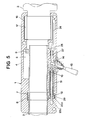
- Figure 5 and 6 show, in the view corresponding to figure 1 and a view from beneath mainly corresponding to figure 4 resp., a modified embodiment of a steering wheel shaft 1 according to the invention. Details having full correspondence in corresponding details in figure 1-4 are given the same references as these.
- This steering wheel shaft 1 thus includes a first steering column tube 2, a second steering column tube 3, a steering wheel shaft housing 4 with an internal seat for the first steering column tube, a groove 6 in which a shoulder 5 provided on the first steering column tube is restrictedly moveable.
- the axial motion of the first steering column tube in the housing can be locked by means of a thrust ring 8 loosely arranged in a groove 7 in the housing, whereby actuating members press against the thrust ring in a manner to displace said ring.
- the actuating members 23 in this case are formed by two cylindric rollers 23a, 23b, which in a seat are located one on each side of a tapering portion 12 on a piston 11 displaceably arranged in a groove in the housing, which piston is biased against a position where the tapering portion 12 is located thus that a first one 23a of the rolling bodies is pressed against the thrust ring and displaces the same, whereas the second rolling body 23b acts as a holder-on for the tapering portion in the seat.
- the seat is provided with a low friction material 29, against which said second rolling body 23b makes a short rolling movement at the displacement of the piston, whereby the starting friction at the begin- nirig of the release movement is minimized, at the same time as the strength is increased.
- the axial displacement of the piston 11 is effected by a control 15 engaging into a recess 14 in the piston.
- a cylindrical seat 16 having its center axis arranged perpendicularly to the longitudinal direction of the steering wheel shaft.
- a hub 17 located at the end of the second steering column tube 3, which hub in one side surface is provided with a toothed segment 24, which in this case projects from the hub and extends into a space where it .
- the body 26 is equipped with a stop 28 arranged to cooperate with the end of the piston 11 facing away from the tapering portion 12, whereby there is a play between said stop 28 and the piston 11, which means that a first part of the piston movement causes that the longitudinal adjustment of the first steering column tube adjustment relative to the steering wheel shaft house is made possible, whereas further displacement of the piston gives a possibility of tilting the second steering column tube relative to the steering wheel shaft housing .
- the piston can be considered to consist of a two-part piston comprising the proper piston part 11 and the body 26.
- FIG 7 a part of the piston 11 in enlarged scale and the actuating part for the thrust ring 8 is in this case designed as a recess 30 in the piston, which recess cooperates with an eccentrically supported body 31, which thus can replace the rolling elements in earlier illustrated embodiments.
- FIG 8 is illustrated how the piston can be divided in two piston parts 11 a, 11 arranged in parallell positions, each serving one of the locking functions and each having an opening 14a and 14b resp. for the control 15.
- the steering column tubes shown in the examples can freely be turned so that either the first steering column tube, which is axially adjustable in relation to the housing, encloses the steering wheel shaft, which extends rotatably therethrough and cooperates with a not shown steering mechanism, whereas the second steering column tube, which is tiltable, encloses the rotatable steering axle with a steering wheel mounted thereon.
- the opposite condition is also possible, i.e. where the axially adjustable steering column tube is turned towards the steering wheel and the tiltable steering column tube is turned towards the steering mechanism.
- the control has consistently in the drawings been shown as a hand operated lever 15, but the control can as well be consituted by a pedal, which transmits the power to the piston via a wire, or the piston itself can be formed as a machine element, which under influence of another external power source performs its displacement.
- the piston may e.g. be constituted by a part of an electromagnet, which at switching over upon an electric switch can be caused to move sufficiently for making the releasing or locking movements.
Landscapes
- Engineering & Computer Science (AREA)
- Chemical & Material Sciences (AREA)
- Combustion & Propulsion (AREA)
- Transportation (AREA)
- Mechanical Engineering (AREA)
- Steering Controls (AREA)
Applications Claiming Priority (2)
| Application Number | Priority Date | Filing Date | Title |
|---|---|---|---|
| SE8501109A SE459331B (sv) | 1985-03-07 | 1985-03-07 | Laengd- och lutningsinstaellbar rattstaang foer fordon |
| SE8501109 | 1985-03-07 |
Publications (2)
| Publication Number | Publication Date |
|---|---|
| EP0199687A1 true EP0199687A1 (fr) | 1986-10-29 |
| EP0199687B1 EP0199687B1 (fr) | 1989-06-28 |
Family
ID=20359394
Family Applications (1)
| Application Number | Title | Priority Date | Filing Date |
|---|---|---|---|
| EP86850080A Expired EP0199687B1 (fr) | 1985-03-07 | 1986-03-05 | Colonne de direction réglable pour véhicules |
Country Status (4)
| Country | Link |
|---|---|
| US (1) | US4709592A (fr) |
| EP (1) | EP0199687B1 (fr) |
| DE (1) | DE3664124D1 (fr) |
| SE (1) | SE459331B (fr) |
Cited By (1)
| Publication number | Priority date | Publication date | Assignee | Title |
|---|---|---|---|---|
| EP0231453A1 (fr) * | 1985-12-27 | 1987-08-12 | Trw Inc. | Colonne de direction inclinable et téléscopique |
Families Citing this family (17)
| Publication number | Priority date | Publication date | Assignee | Title |
|---|---|---|---|---|
| GB2217817A (en) * | 1988-04-30 | 1989-11-01 | Ford Motor Co | A steering column construction |
| US5009120A (en) * | 1990-02-23 | 1991-04-23 | General Motors Corporation | Manual control for adjustable steering column |
| GB2263756A (en) * | 1992-01-24 | 1993-08-04 | Ford Motor Co | Adjustment mechanism for vehicle steering columns. |
| US5363716A (en) * | 1993-04-01 | 1994-11-15 | Trw Inc. | Tilt-telescope steering column |
| US5613404A (en) * | 1994-03-07 | 1997-03-25 | Case Corporation | Tiltable steering mechanism for an off-highway implement |
| US5537890A (en) * | 1995-05-17 | 1996-07-23 | General Motors Corporation | Motor vehicle steering column |
| US5678454A (en) * | 1995-06-15 | 1997-10-21 | Trw Inc. | Steering column |
| JP3728913B2 (ja) * | 1998-02-06 | 2005-12-21 | 日本精工株式会社 | 車両用ステアリング装置 |
| US6134983A (en) * | 1999-05-06 | 2000-10-24 | Delphi Technologies, Inc. | Motor vehicle steering column and method |
| KR100377435B1 (ko) * | 2000-12-01 | 2003-03-26 | 주식회사 만도 | 차량용 스티어링 컬럼의 위치조절장치 |
| US6868750B2 (en) * | 2001-11-21 | 2005-03-22 | Hyundai Mobis Co., Ltd. | Telescopic device of steering column for vehicle |
| US7438320B2 (en) * | 2003-12-16 | 2008-10-21 | Nsk Ltd. | Steering column for motor vehicle |
| US7503234B2 (en) * | 2005-05-26 | 2009-03-17 | Delphi Technologies, Inc. | One lever tilt and telescope mechanism |
| US20080141815A1 (en) * | 2006-10-12 | 2008-06-19 | Ridgway Jason R | Steering column assembly for a vehicle |
| US7587959B2 (en) * | 2007-02-09 | 2009-09-15 | Delphi Technologies, Inc. | Steering column assembly |
| US7730804B2 (en) * | 2007-03-21 | 2010-06-08 | Gm Global Technology Operations, Inc. | Central lock device of an adjustable steering column assembly |
| DE102011110701A1 (de) * | 2011-08-16 | 2013-02-21 | GM Global Technology Operations LLC (n. d. Gesetzen des Staates Delaware) | Verstelleinrichtung |
Citations (6)
| Publication number | Priority date | Publication date | Assignee | Title |
|---|---|---|---|---|
| GB764577A (en) * | 1955-02-16 | 1956-12-28 | Jaguar Cars | Axially-adjustable steering shafts |
| US3245282A (en) * | 1964-04-13 | 1966-04-12 | Gen Motors Corp | Progressively adjustable steering assembly |
| US3285090A (en) * | 1965-05-20 | 1966-11-15 | Gen Motors Corp | Adjustable steering column |
| US3302478A (en) * | 1965-03-26 | 1967-02-07 | Bendix Corp | Adjustable steering column |
| GB1137400A (en) * | 1965-11-26 | 1968-12-18 | Borg Warner | Adjustable steering column |
| EP0094520A1 (fr) * | 1982-05-14 | 1983-11-23 | John Willy Höiseth | Dispositif pour le blocage de deux membres |
Family Cites Families (5)
| Publication number | Priority date | Publication date | Assignee | Title |
|---|---|---|---|---|
| US2903904A (en) * | 1958-03-19 | 1959-09-15 | Gen Motors Corp | Adjustable steering column and shaft |
| GB1217055A (en) * | 1967-12-14 | 1970-12-23 | Bendix Corp | Improvements relating to the elimination of torsional lash in an axially movable steering column |
| AT337015B (de) * | 1975-03-13 | 1977-06-10 | Steyr Daimler Puch Ag | Vorrichtung zur lenkradverstellung bei kraftfahrzeugen |
| DE3016212A1 (de) * | 1980-04-26 | 1981-10-29 | Volkswagenwerk Ag, 3180 Wolfsburg | Laengen- und neigungsverstellbare lenksaeule fuer ein fahrzeug |
| JPS58152661A (ja) * | 1982-03-09 | 1983-09-10 | Aisin Seiki Co Ltd | ステアリングシヤフトの長さ調整装置 |
-
1985
- 1985-03-07 SE SE8501109A patent/SE459331B/sv not_active IP Right Cessation
-
1986
- 1986-03-05 DE DE8686850080T patent/DE3664124D1/de not_active Expired
- 1986-03-05 EP EP86850080A patent/EP0199687B1/fr not_active Expired
- 1986-03-07 US US06/837,250 patent/US4709592A/en not_active Expired - Fee Related
Patent Citations (6)
| Publication number | Priority date | Publication date | Assignee | Title |
|---|---|---|---|---|
| GB764577A (en) * | 1955-02-16 | 1956-12-28 | Jaguar Cars | Axially-adjustable steering shafts |
| US3245282A (en) * | 1964-04-13 | 1966-04-12 | Gen Motors Corp | Progressively adjustable steering assembly |
| US3302478A (en) * | 1965-03-26 | 1967-02-07 | Bendix Corp | Adjustable steering column |
| US3285090A (en) * | 1965-05-20 | 1966-11-15 | Gen Motors Corp | Adjustable steering column |
| GB1137400A (en) * | 1965-11-26 | 1968-12-18 | Borg Warner | Adjustable steering column |
| EP0094520A1 (fr) * | 1982-05-14 | 1983-11-23 | John Willy Höiseth | Dispositif pour le blocage de deux membres |
Cited By (1)
| Publication number | Priority date | Publication date | Assignee | Title |
|---|---|---|---|---|
| EP0231453A1 (fr) * | 1985-12-27 | 1987-08-12 | Trw Inc. | Colonne de direction inclinable et téléscopique |
Also Published As
| Publication number | Publication date |
|---|---|
| SE8501109L (sv) | 1986-09-08 |
| SE8501109D0 (sv) | 1985-03-07 |
| US4709592A (en) | 1987-12-01 |
| DE3664124D1 (en) | 1989-08-03 |
| EP0199687B1 (fr) | 1989-06-28 |
| SE459331B (sv) | 1989-06-26 |
Similar Documents
| Publication | Publication Date | Title |
|---|---|---|
| EP0199687B1 (fr) | Colonne de direction réglable pour véhicules | |
| US5340342A (en) | Universal tiller handle with shift and throttle | |
| EP2963314B1 (fr) | Dispositif de commutation de plage de changement de rapport pour véhicule | |
| US4821605A (en) | Transmission shift control assembly | |
| US7213484B2 (en) | Steering column apparatus | |
| EP0156114B1 (fr) | Blocage de position axiale pour colonne de direction télescopique | |
| KR970058986A (ko) | 차량시트용 힌지기구 및 이러한 기구를 포함하는 시트 | |
| GB2169065A (en) | Indexing mechanisms and controls embodying the same | |
| US4727765A (en) | Shift mechanism for manual transmission | |
| JPS6241903B2 (fr) | ||
| US6123639A (en) | Apparatus for actuating a switching shaft operatively connected with a switchable bottom bracket bearing gear | |
| EP0149020A2 (fr) | Dispositifs pour le changement de vitesse et pour la commande d'une transmission en particulier pour véhicules industriels | |
| US5025678A (en) | Column shift lever device | |
| IE42963B1 (en) | Articulation for vehicle seat comprising a ball mounted reducing element | |
| AU726506B2 (en) | Bolt actuation apparatus | |
| EP3348450B1 (fr) | Colonne de direction | |
| US3487711A (en) | Movable steering column having transmission shift lever interconnection | |
| US4096717A (en) | Transmission shift control | |
| JPH088939Y2 (ja) | テレスコピック・ステアリング装置 | |
| JPS638971Y2 (fr) | ||
| JP2016088186A (ja) | シフトレバーユニット | |
| JPH0540896Y2 (fr) | ||
| JPS62258860A (ja) | テレスコピツクステアリング装置 | |
| EP1086851B1 (fr) | Accoudoir pour siège de véhicule automobile | |
| JP3095587B2 (ja) | チェンジレバーユニット |
Legal Events
| Date | Code | Title | Description |
|---|---|---|---|
| PUAI | Public reference made under article 153(3) epc to a published international application that has entered the european phase |
Free format text: ORIGINAL CODE: 0009012 |
|
| AK | Designated contracting states |
Kind code of ref document: A1 Designated state(s): DE FR GB IT |
|
| 17P | Request for examination filed |
Effective date: 19870415 |
|
| 17Q | First examination report despatched |
Effective date: 19880108 |
|
| GRAA | (expected) grant |
Free format text: ORIGINAL CODE: 0009210 |
|
| AK | Designated contracting states |
Kind code of ref document: B1 Designated state(s): DE FR GB IT |
|
| REF | Corresponds to: |
Ref document number: 3664124 Country of ref document: DE Date of ref document: 19890803 |
|
| ET | Fr: translation filed | ||
| ITF | It: translation for a ep patent filed | ||
| PLBE | No opposition filed within time limit |
Free format text: ORIGINAL CODE: 0009261 |
|
| STAA | Information on the status of an ep patent application or granted ep patent |
Free format text: STATUS: NO OPPOSITION FILED WITHIN TIME LIMIT |
|
| 26N | No opposition filed | ||
| PGFP | Annual fee paid to national office [announced via postgrant information from national office to epo] |
Ref country code: GB Payment date: 19910305 Year of fee payment: 6 |
|
| PGFP | Annual fee paid to national office [announced via postgrant information from national office to epo] |
Ref country code: FR Payment date: 19910326 Year of fee payment: 6 |
|
| ITTA | It: last paid annual fee | ||
| PGFP | Annual fee paid to national office [announced via postgrant information from national office to epo] |
Ref country code: DE Payment date: 19910530 Year of fee payment: 6 |
|
| PG25 | Lapsed in a contracting state [announced via postgrant information from national office to epo] |
Ref country code: GB Effective date: 19920305 |
|
| PGFP | Annual fee paid to national office [announced via postgrant information from national office to epo] |
Ref country code: LU Payment date: 19920811 Year of fee payment: 8 |
|
| GBPC | Gb: european patent ceased through non-payment of renewal fee | ||
| PG25 | Lapsed in a contracting state [announced via postgrant information from national office to epo] |
Ref country code: FR Effective date: 19921130 |
|
| PG25 | Lapsed in a contracting state [announced via postgrant information from national office to epo] |
Ref country code: DE Effective date: 19921201 |
|
| EPTA | Lu: last paid annual fee | ||
| REG | Reference to a national code |
Ref country code: FR Ref legal event code: ST |
|
| PG25 | Lapsed in a contracting state [announced via postgrant information from national office to epo] |
Ref country code: IT Free format text: LAPSE BECAUSE OF NON-PAYMENT OF DUE FEES Effective date: 20050305 |