EP0094868B1 - Verfahren zur Herstellung eines aufblasbaren Schuhes mit verschiedenen Drucken an verschiedenen Stellen und Rohling zur Herstellung eines solchen Schuhes - Google Patents
Verfahren zur Herstellung eines aufblasbaren Schuhes mit verschiedenen Drucken an verschiedenen Stellen und Rohling zur Herstellung eines solchen Schuhes Download PDFInfo
- Publication number
- EP0094868B1 EP0094868B1 EP83400922A EP83400922A EP0094868B1 EP 0094868 B1 EP0094868 B1 EP 0094868B1 EP 83400922 A EP83400922 A EP 83400922A EP 83400922 A EP83400922 A EP 83400922A EP 0094868 B1 EP0094868 B1 EP 0094868B1
- Authority
- EP
- European Patent Office
- Prior art keywords
- footwear
- cavities
- rough shape
- inflated
- passages
- Prior art date
- Legal status (The legal status is an assumption and is not a legal conclusion. Google has not performed a legal analysis and makes no representation as to the accuracy of the status listed.)
- Expired
Links
- 238000004519 manufacturing process Methods 0.000 title claims abstract description 6
- 238000004891 communication Methods 0.000 claims abstract description 11
- 210000002445 nipple Anatomy 0.000 claims abstract 8
- 210000003423 ankle Anatomy 0.000 claims description 26
- 238000003466 welding Methods 0.000 claims description 10
- 238000000034 method Methods 0.000 claims description 8
- 239000000463 material Substances 0.000 claims description 3
- 230000000694 effects Effects 0.000 claims description 2
- 239000012775 heat-sealing material Substances 0.000 claims 1
- 239000007787 solid Substances 0.000 claims 1
- 210000002683 foot Anatomy 0.000 description 11
- 238000011282 treatment Methods 0.000 description 6
- 230000000399 orthopedic effect Effects 0.000 description 5
- 229920002635 polyurethane Polymers 0.000 description 4
- 239000004814 polyurethane Substances 0.000 description 4
- 210000004744 fore-foot Anatomy 0.000 description 3
- 208000004067 Flatfoot Diseases 0.000 description 2
- 208000000013 Hammer Toe Syndrome Diseases 0.000 description 2
- 230000006835 compression Effects 0.000 description 2
- 238000007906 compression Methods 0.000 description 2
- 210000003041 ligament Anatomy 0.000 description 2
- 238000007789 sealing Methods 0.000 description 2
- 206010010356 Congenital anomaly Diseases 0.000 description 1
- 206010023204 Joint dislocation Diseases 0.000 description 1
- 210000001361 achilles tendon Anatomy 0.000 description 1
- 230000006978 adaptation Effects 0.000 description 1
- 210000000544 articulatio talocruralis Anatomy 0.000 description 1
- 230000005540 biological transmission Effects 0.000 description 1
- 239000004744 fabric Substances 0.000 description 1
- 238000005304 joining Methods 0.000 description 1
- 238000012423 maintenance Methods 0.000 description 1
- 230000000877 morphologic effect Effects 0.000 description 1
- 230000003387 muscular Effects 0.000 description 1
- 238000007665 sagging Methods 0.000 description 1
- 230000035939 shock Effects 0.000 description 1
- 210000000457 tarsus Anatomy 0.000 description 1
- 239000004753 textile Substances 0.000 description 1
- 230000001225 therapeutic effect Effects 0.000 description 1
- 230000000472 traumatic effect Effects 0.000 description 1
Images

Classifications
-
- A—HUMAN NECESSITIES
- A43—FOOTWEAR
- A43B—CHARACTERISTIC FEATURES OF FOOTWEAR; PARTS OF FOOTWEAR
- A43B17/00—Insoles for insertion, e.g. footbeds or inlays, for attachment to the shoe after the upper has been joined
- A43B17/02—Insoles for insertion, e.g. footbeds or inlays, for attachment to the shoe after the upper has been joined wedge-like or resilient
- A43B17/03—Insoles for insertion, e.g. footbeds or inlays, for attachment to the shoe after the upper has been joined wedge-like or resilient filled with a gas, e.g. air
- A43B17/035—Insoles for insertion, e.g. footbeds or inlays, for attachment to the shoe after the upper has been joined wedge-like or resilient filled with a gas, e.g. air provided with a pump or valve
Definitions
- the present invention relates to footwear, this term encompassing the soles added in shoes of all types, the uppers and uppers, associated or not with a sole, incorporated in the same shoes and the slippers or light footwear which can be worn. alone or placed in other footwear.
- the present invention more specifically aims to produce an orthopedic footwear capable of providing selective support or maintenance of the different parts of the foot, possibly of the leg, associated or not with a compression of some of these parts.
- the footwear because of its characteristics, can also be used as a comfort element in sports shoes and other footwear in common use.
- the inflatable part can be limited to the sole, to the upper or to a part thereof, in particular to the interlocking of the tarsus, or to surround a large part of the foot and even to go back up to fit the leg as in ski boots, as described in FR-A 2144464.
- the chamber or chambers constituting the inflatable part are produced by sealed waterproof pockets optionally removable as described in US-A 4083127, networks of tubes or cavities formed in particular in the sole as described in FR-A 4083127, networks of tubes or cavities formed in particular in the sole as described in FR-A 2458239 and the different chambers are in communication with each other when the article is actually inflatable but they can be isolated when it is a "pneumatic" sole "
- the invention aims to create an inflatable footwear which overcomes the disadvantages and inadequacies of articles of the same kind previously known and which, by its constitution, is capable of producing a real orthopedic article.
- the method for producing an article of footwear inflated pneumatically to different pressures in its different zones in which a blank is used consisting of a set of cavities intercommunicating by passages of reduced section and connected to at least one inflation fitting is characterized in that the blank is inflated to the desired pressure for the cavity furthest from the fitting and isolates the latter by closing the passages ensuring its communication with the other cavities of the blank and repeating the operation successively for each cavity not yet inflated and furthest from the inflation fitting by modifying the pressure until all the cavities are inflated to the desired pressures and isolated.
- the draft footwear for the implementation of the method according to the invention has on its surface cavities intercommunicating by passages of reduced section and connected to at least one inflation fitting and is characterized in that at least some of the passages of reduced section ensuring intercommunication between the inflation fitting and some of the cavities, can be closed after pneumatic inflation of the cavities.
- certain parts corresponding to certain cavities must provide a compression which can be variable over time, for example during the evolution of the mal-position, or which can vary because the shape assembly of these parts is not fixed, for example the assembly of the parts constituting an ankle which must be separated to fit the article, the cavities of these parts preferably remain in communication with the inflation fitting (s).
- the assembly of the inflatable pocket subdivided into the different cavities is secured with at least one skin or lining layer arranged on its two faces.
- At least certain cavities are preformed in their deformation by junction elements joining the two walls of the cavity concerned so as to avoid the balloon deformation of said cavity under the effect of the inflation pressure.
- One of the walls of the cavity can be made of a thermoformable material, said wall being preformed substantially to the shape which it must have after pneumatic inflation in the finished footwear.
- the two walls of the inflatable bag are made of a heat-sealable material, the subdivision into the different cavities and the junction elements being produced by heat-sealings.
- the two walls are made of polyurethane sheets and the heat seals are made by high frequency welding.
- the passages of closable reduced section are produced by interruptions of the heat seals of the blank and their sealing during the implementation of the process is ensured by a heat seal.
- the locations of the closable communication passages between the cavities are identified on at least one of the lining layers or skins, for example by windows for engaging the welding electrodes.
- the sole surface is subdivided into a heel wedge zone, sub-scaphoid and sub-cuboid support zones, zones corresponding to the retro-capital, sub-capital and ante-capital bars and the sole is associated. with an ankle brace.
- Some of the zones can themselves be subdivided so that their different parts can be inflated differently. This is particularly so of the parts constituting the ankle which are subdivided into vertical chambers and of the sub-capital bar subdivided into longitudinal chambers.
- references 1 and 2 denote the polyurethane sheets constituting the upper wall and the lower wall of the inflatable bag; 3 denotes the textile lining applied to the upper wall and 4 the skin applied to the lower wall.
- the forming heat seals are designated by 5 and the various passages by the reference 6 assigned a letter and possibly an exponent when they are intended to be closed.
- Reference 7 designates an orifice or window in the skin 4 for the passage of the welding electrodes.
- the reference 8 designates the assembly bands of the ankle forming part behind the Achilles tendon, the reference 9 the closure bands, for example covered with adhering fabric of the type sold under the brand "Velcro", of the front part of the ankle and 10 the malleoli release windows.
- Reference 11 designates the inflation fitting.
- the liner shown is specific for a straight foot, but it is possible, by assembling polyurethane sheets flat and not preformed and identical leathers on both sides, to produce a blank usable for both feet.
- the surface of the blank is divided into various zones respectively the anterior-capital bar 12, the sub-capital bar 13, the retro-capital bar 14, the internal 15 and external 16 sub-cuboid supports, the internal sub-scaphoid supports 17 and external 18, the heel wedge 19, the anterior parts 20 of the ankle and the posterior parts 21.
- the posterior parts 21 of the ankle are in communication by a channel 23 bypassing the heel.
- the sub-capital 13 and retro-capital 15 bars and the parts of the ankle are subdivided by bridging heat seals 5a and the polyurethane sheet 2 is thermoformed in the parts forming the ankle to give tubular cavities 22 of larger section under moderate inflation pressure. The thicknesses are exaggerated in Figure 2.
- the sub-capital part 13 is in communication with the cavity of the ante-capital bar 12 by passages 6a and the sub-capital part can be subdivided by welding passages 6b.
- the retro-capital part 14 communicates with the ante-capital bar by closable passages 6c.
- the ante-capital bar communicates with the sub-cuboid and sub-scaphoid supports by 6d closable passages; the internal and external supports, sub-cuboid and sub-scaphoid, are in communication by closable passages 6e.
- the sub-cuboid and sub-scaphoid supports 16 and 18 communicate with the heel wedge 19 by closable passages 6f and with the parts of the anterior ankles 20 by passages 6g.
- the heel wedge communicates with the posterior ankle parts by 6h passages and the anterior and posterior ankle parts communicate together by 6i passages.
- the one part of the posterior ankle is in communication with the inflation valve 11.
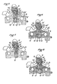
- Figure 3 illustrates the use of the slipper for the treatment of flat foot with ankle instability characterized more particularly by ligament instability of the ankle, heel instability, sub-scaphoid sagging and a flat forefoot.
- Figure 4 corresponds to a hollow foot with instability of the ankle and claw toes.
- the sub- and retro-capitals bars are isolated by welding the passages 6a ′ and 6c ′, the external sub-cuboid support 16, the tallon landlocking 19 and the parts forming an ankle 20 and 21.
- Figure 5 concerns the treatment of a typically feminine hollow foot.
- the sub-capital bar 13 is isolated by welding the two passages 6a ', after having inflated it to normal pressure. The pressure is then reduced and the anterior capital bar 12, the front part of the retro-capital bar 14, the sub-scaphoid supports 17-18, the internal sub-cuboid support 15 and possibly the anterior ankle parts 20 are isolated.
- the sub-cuboid and the retro-capital bar can be isolated by welding the passage 6f "to avoid the transmission of air between the two bearings.
- Figure 6 corresponds to the indication of a hollow anterior anterior arcuate foot with hammer toes, requiring an ankle, a wedge heel, sub-cuboid support and an ante-capital bar.
- the sub-capital and retro-capital bars are isolated by welding passages 6a 'and 6c', the passage 6d 'is closed between the ante-capital bar 12 and the sub-scaphoid supports 17-18, the passage 6f 'between the sub-scaphoid and the heel wedge, the passages 6i' and the passage 6g 'between the sub-cuboid and the anterior part of the ankle joint after which the intercommunicating cavities are inflated.
- welds 6 0 'substituted for welds 6c' it is possible, by welds 6 0 'substituted for welds 6c', to pressurize the rear strip of the retro-capital part and also to isolate after inflation the different zones by closing the passages 6d ', 6h', etc. .
- Figure 7 illustrates the treatment of a flat foot with spread out forefoot. After moderate inflation, a lateral part of the sub-capital bar and the front strip of the retro-capital bar are isolated by the welds 6a ′, 6b ′′ and 6p ′. internal scaphoid and sub-cuboid 15 and 17 after which the other cavities of the sole are inflated which can be isolated between them and isolate parts forming the ankle which can be brought to a moderate pressure.
- Figure 8 illustrates the treatment of a hollow foot with convex forefoot.
- a lateral part of the sub-capital bar is isolated by closing the passage 6b 'and a lateral passage 6a'.
- a moderate pressure is then established and closes the passages 6f ', 6i', 6d ', 6 0 ', 6p ', 6g' and 6e 'indicated to isolate at this pressure the rear strip of the retro-capital bar the sub-scaphoid internal 17, the sub-scuboid 15-16 and the anterior parts of the ankle, after which the pressure is inflated to normal pressure and the various inflated pads are isolated if necessary.
Landscapes
- Footwear And Its Accessory, Manufacturing Method And Apparatuses (AREA)
Claims (10)
Priority Applications (1)
| Application Number | Priority Date | Filing Date | Title |
|---|---|---|---|
| AT83400922T ATE24100T1 (de) | 1982-05-14 | 1983-05-06 | Verfahren zur herstellung eines aufblasbaren schuhes mit verschiedenen drucken an verschiedenen stellen und rohling zur herstellung eines solchen schuhes. |
Applications Claiming Priority (2)
| Application Number | Priority Date | Filing Date | Title |
|---|---|---|---|
| FR8208541A FR2526643A1 (fr) | 1982-05-14 | 1982-05-14 | Procede de realisation d'articles chaussants gonfles a des pressions differentes dans leurs differentes zones et ebauche pour sa mise en oeuvre |
| FR8208541 | 1982-05-14 |
Publications (2)
| Publication Number | Publication Date |
|---|---|
| EP0094868A1 EP0094868A1 (de) | 1983-11-23 |
| EP0094868B1 true EP0094868B1 (de) | 1986-12-10 |
Family
ID=9274093
Family Applications (1)
| Application Number | Title | Priority Date | Filing Date |
|---|---|---|---|
| EP83400922A Expired EP0094868B1 (de) | 1982-05-14 | 1983-05-06 | Verfahren zur Herstellung eines aufblasbaren Schuhes mit verschiedenen Drucken an verschiedenen Stellen und Rohling zur Herstellung eines solchen Schuhes |
Country Status (4)
| Country | Link |
|---|---|
| EP (1) | EP0094868B1 (de) |
| AT (1) | ATE24100T1 (de) |
| DE (1) | DE3368186D1 (de) |
| FR (1) | FR2526643A1 (de) |
Cited By (26)
| Publication number | Priority date | Publication date | Assignee | Title |
|---|---|---|---|---|
| US5416988A (en) | 1989-03-17 | 1995-05-23 | Nike, Inc. | Customized fit shoe and bladder therefor |
| US5765298A (en) | 1989-03-17 | 1998-06-16 | Nike, Inc. | Athletic shoe with pressurized ankle collar |
| US6374514B1 (en) | 2000-03-16 | 2002-04-23 | Nike, Inc. | Footwear having a bladder with support members |
| US6385864B1 (en) | 2000-03-16 | 2002-05-14 | Nike, Inc. | Footwear bladder with controlled flex tensile member |
| US6402879B1 (en) | 2000-03-16 | 2002-06-11 | Nike, Inc. | Method of making bladder with inverted edge seam |
| US6457262B1 (en) | 2000-03-16 | 2002-10-01 | Nike, Inc. | Article of footwear with a motion control device |
| US6571490B2 (en) | 2000-03-16 | 2003-06-03 | Nike, Inc. | Bladder with multi-stage regionalized cushioning |
| US6931764B2 (en) | 2003-08-04 | 2005-08-23 | Nike, Inc. | Footwear sole structure incorporating a cushioning component |
| US6971193B1 (en) | 2002-03-06 | 2005-12-06 | Nike, Inc. | Bladder with high pressure replenishment reservoir |
| US7000335B2 (en) | 2003-07-16 | 2006-02-21 | Nike, Inc. | Footwear with a sole structure incorporating a lobed fluid-filled chamber |
| US7086179B2 (en) | 2003-12-23 | 2006-08-08 | Nike, Inc. | Article of footwear having a fluid-filled bladder with a reinforcing structure |
| US7086180B2 (en) | 2003-12-23 | 2006-08-08 | Nike, Inc. | Article of footwear having a fluid-filled bladder with a reinforcing structure |
| US7100310B2 (en) | 2003-12-23 | 2006-09-05 | Nike, Inc. | Article of footwear having a fluid-filled bladder with a reinforcing structure |
| US7141131B2 (en) | 2003-12-23 | 2006-11-28 | Nike, Inc. | Method of making article of footwear having a fluid-filled bladder with a reinforcing structure |
| US7156787B2 (en) | 2003-12-23 | 2007-01-02 | Nike, Inc. | Inflatable structure and method of manufacture |
| US7434339B2 (en) | 2003-07-16 | 2008-10-14 | Nike, Inc. | Footwear with a sole structure incorporating a lobed fluid-filled chamber |
| US7448522B2 (en) | 2003-11-11 | 2008-11-11 | Nike, Inc. | Fluid-filled bladder for use with strap |
| US7533477B2 (en) | 2005-10-03 | 2009-05-19 | Nike, Inc. | Article of footwear with a sole structure having fluid-filled support elements |
| US7556846B2 (en) | 2003-12-23 | 2009-07-07 | Nike, Inc. | Fluid-filled bladder with a reinforcing structure |
| US7562469B2 (en) | 2003-12-23 | 2009-07-21 | Nike, Inc. | Footwear with fluid-filled bladder and a reinforcing structure |
| US7622014B2 (en) | 2005-07-01 | 2009-11-24 | Reebok International Ltd. | Method for manufacturing inflatable footwear or bladders for use in inflatable articles |
| US7707744B2 (en) | 2003-07-16 | 2010-05-04 | Nike, Inc. | Footwear with a sole structure incorporating a lobed fluid-filled chamber |
| US7707745B2 (en) | 2003-07-16 | 2010-05-04 | Nike, Inc. | Footwear with a sole structure incorporating a lobed fluid-filled chamber |
| US7810255B2 (en) | 2007-02-06 | 2010-10-12 | Nike, Inc. | Interlocking fluid-filled chambers for an article of footwear |
| US7950169B2 (en) | 2007-05-10 | 2011-05-31 | Nike, Inc. | Contoured fluid-filled chamber |
| US8572786B2 (en) | 2010-10-12 | 2013-11-05 | Reebok International Limited | Method for manufacturing inflatable bladders for use in footwear and other articles of manufacture |
Families Citing this family (7)
| Publication number | Priority date | Publication date | Assignee | Title |
|---|---|---|---|---|
| GB2168234B (en) * | 1984-11-19 | 1988-04-27 | John Alan Drew | Orthopaedic footwear |
| US5353459A (en) * | 1993-09-01 | 1994-10-11 | Nike, Inc. | Method for inflating a bladder |
| FR2717350B1 (fr) * | 1994-03-17 | 1996-05-10 | Jesus Garcia | Chaussures pour activités sportives. |
| US5753061A (en) * | 1995-06-05 | 1998-05-19 | Robert C. Bogert | Multi-celled cushion and method of its manufacture |
| US6430843B1 (en) | 2000-04-18 | 2002-08-13 | Nike, Inc. | Dynamically-controlled cushioning system for an article of footwear |
| ITFO20110002A1 (it) * | 2011-04-11 | 2012-10-12 | Ebro Bondi | Plantare per calzature |
| US9737114B2 (en) | 2014-08-06 | 2017-08-22 | Nike, Inc. | Articles of footwear with upper incorporating chamber element |
Family Cites Families (4)
| Publication number | Priority date | Publication date | Assignee | Title |
|---|---|---|---|---|
| US2677906A (en) * | 1952-08-14 | 1954-05-11 | Reed Arnold | Cushioned inner sole for shoes and meth od of making the same |
| US3758964A (en) * | 1971-10-25 | 1973-09-18 | Onitsuka Co Ltd | Sports shoe |
| US4083127A (en) * | 1977-03-17 | 1978-04-11 | Hanson Industries Incorporated | Adjustable, pressure-compensating, custom fitting pads having predetermined amount of fitting material and their use in boots |
| IT7960923U1 (it) * | 1979-06-07 | 1980-12-07 | Garzia Carmine | Sottopiede per calzature e simili apprestante piu' camere d'aria parzialmente comunicanti atto a distribuire la pressione su tutta la pianta del piede |
-
1982
- 1982-05-14 FR FR8208541A patent/FR2526643A1/fr active Granted
-
1983
- 1983-05-06 AT AT83400922T patent/ATE24100T1/de not_active IP Right Cessation
- 1983-05-06 EP EP83400922A patent/EP0094868B1/de not_active Expired
- 1983-05-06 DE DE8383400922T patent/DE3368186D1/de not_active Expired
Cited By (39)
| Publication number | Priority date | Publication date | Assignee | Title |
|---|---|---|---|---|
| US5765298A (en) | 1989-03-17 | 1998-06-16 | Nike, Inc. | Athletic shoe with pressurized ankle collar |
| US5416988A (en) | 1989-03-17 | 1995-05-23 | Nike, Inc. | Customized fit shoe and bladder therefor |
| US7132032B2 (en) | 2000-03-16 | 2006-11-07 | Nike, Inc. | Bladder with multi-stage regionalized cushioning |
| US6374514B1 (en) | 2000-03-16 | 2002-04-23 | Nike, Inc. | Footwear having a bladder with support members |
| US6385864B1 (en) | 2000-03-16 | 2002-05-14 | Nike, Inc. | Footwear bladder with controlled flex tensile member |
| US6402879B1 (en) | 2000-03-16 | 2002-06-11 | Nike, Inc. | Method of making bladder with inverted edge seam |
| US6457262B1 (en) | 2000-03-16 | 2002-10-01 | Nike, Inc. | Article of footwear with a motion control device |
| US6571490B2 (en) | 2000-03-16 | 2003-06-03 | Nike, Inc. | Bladder with multi-stage regionalized cushioning |
| US7244483B2 (en) | 2000-03-16 | 2007-07-17 | Nike, Inc. | Bladder with inverted edge seam and method of making the bladder |
| US6971193B1 (en) | 2002-03-06 | 2005-12-06 | Nike, Inc. | Bladder with high pressure replenishment reservoir |
| US7434339B2 (en) | 2003-07-16 | 2008-10-14 | Nike, Inc. | Footwear with a sole structure incorporating a lobed fluid-filled chamber |
| US7000335B2 (en) | 2003-07-16 | 2006-02-21 | Nike, Inc. | Footwear with a sole structure incorporating a lobed fluid-filled chamber |
| US7707745B2 (en) | 2003-07-16 | 2010-05-04 | Nike, Inc. | Footwear with a sole structure incorporating a lobed fluid-filled chamber |
| US7707744B2 (en) | 2003-07-16 | 2010-05-04 | Nike, Inc. | Footwear with a sole structure incorporating a lobed fluid-filled chamber |
| US6931764B2 (en) | 2003-08-04 | 2005-08-23 | Nike, Inc. | Footwear sole structure incorporating a cushioning component |
| US7448522B2 (en) | 2003-11-11 | 2008-11-11 | Nike, Inc. | Fluid-filled bladder for use with strap |
| US7100310B2 (en) | 2003-12-23 | 2006-09-05 | Nike, Inc. | Article of footwear having a fluid-filled bladder with a reinforcing structure |
| US7141131B2 (en) | 2003-12-23 | 2006-11-28 | Nike, Inc. | Method of making article of footwear having a fluid-filled bladder with a reinforcing structure |
| US7401420B2 (en) | 2003-12-23 | 2008-07-22 | Nike, Inc. | Article of footwear having a fluid-filled bladder with a reinforcing structure |
| US7086180B2 (en) | 2003-12-23 | 2006-08-08 | Nike, Inc. | Article of footwear having a fluid-filled bladder with a reinforcing structure |
| US8657979B2 (en) | 2003-12-23 | 2014-02-25 | Nike, Inc. | Method of manufacturing a fluid-filled bladder with a reinforcing structure |
| US7556846B2 (en) | 2003-12-23 | 2009-07-07 | Nike, Inc. | Fluid-filled bladder with a reinforcing structure |
| US7562469B2 (en) | 2003-12-23 | 2009-07-21 | Nike, Inc. | Footwear with fluid-filled bladder and a reinforcing structure |
| US7156787B2 (en) | 2003-12-23 | 2007-01-02 | Nike, Inc. | Inflatable structure and method of manufacture |
| US7086179B2 (en) | 2003-12-23 | 2006-08-08 | Nike, Inc. | Article of footwear having a fluid-filled bladder with a reinforcing structure |
| US8540838B2 (en) | 2005-07-01 | 2013-09-24 | Reebok International Limited | Method for manufacturing inflatable footwear or bladders for use in inflatable articles |
| US7622014B2 (en) | 2005-07-01 | 2009-11-24 | Reebok International Ltd. | Method for manufacturing inflatable footwear or bladders for use in inflatable articles |
| US8656608B2 (en) | 2005-10-03 | 2014-02-25 | Nike, Inc. | Article of footwear with a sole structure having fluid-filled support elements |
| US7810256B2 (en) | 2005-10-03 | 2010-10-12 | Nike, Inc. | Article of footwear with a sole structure having fluid-filled support elements |
| US8302234B2 (en) | 2005-10-03 | 2012-11-06 | Nike, Inc. | Article of footwear with a sole structure having fluid-filled support elements |
| US8302328B2 (en) | 2005-10-03 | 2012-11-06 | Nike, Inc. | Article of footwear with a sole structure having fluid-filled support elements |
| US8312643B2 (en) | 2005-10-03 | 2012-11-20 | Nike, Inc. | Article of footwear with a sole structure having fluid-filled support elements |
| US7774955B2 (en) | 2005-10-03 | 2010-08-17 | Nike, Inc. | Article of footwear with a sole structure having fluid-filled support elements |
| US7533477B2 (en) | 2005-10-03 | 2009-05-19 | Nike, Inc. | Article of footwear with a sole structure having fluid-filled support elements |
| US7810255B2 (en) | 2007-02-06 | 2010-10-12 | Nike, Inc. | Interlocking fluid-filled chambers for an article of footwear |
| US7950169B2 (en) | 2007-05-10 | 2011-05-31 | Nike, Inc. | Contoured fluid-filled chamber |
| US8911577B2 (en) | 2007-05-10 | 2014-12-16 | Nike, Inc. | Contoured fluid-filled chamber |
| US9345286B2 (en) | 2007-05-10 | 2016-05-24 | Nike, Inc. | Contoured fluid-filled chamber |
| US8572786B2 (en) | 2010-10-12 | 2013-11-05 | Reebok International Limited | Method for manufacturing inflatable bladders for use in footwear and other articles of manufacture |
Also Published As
| Publication number | Publication date |
|---|---|
| DE3368186D1 (en) | 1987-01-22 |
| FR2526643A1 (fr) | 1983-11-18 |
| FR2526643B1 (de) | 1985-01-11 |
| EP0094868A1 (de) | 1983-11-23 |
| ATE24100T1 (de) | 1986-12-15 |
Similar Documents
| Publication | Publication Date | Title |
|---|---|---|
| EP0094868B1 (de) | Verfahren zur Herstellung eines aufblasbaren Schuhes mit verschiedenen Drucken an verschiedenen Stellen und Rohling zur Herstellung eines solchen Schuhes | |
| EP0032084B1 (de) | Schuhe, insbesondere Sportschuhe | |
| US3084695A (en) | Method of making arch supporting cushion innersole | |
| CN102655775B (zh) | 流体填充结构 | |
| FR2496423A1 (fr) | Chaussure de ski | |
| US4005532A (en) | Insulated insole construction | |
| EP1494627B1 (de) | Schiene für eine gelenkverbindung und verfahren zur herstellung einer solchen schiene | |
| EP0004829A2 (de) | Verfahren zum Anpassen eines Bekleidungselementes oder Zubehörs an einen Teil des menschlichen Körpers und Element oder Zubehör zur Durchführung des Verfahrens | |
| US6149852A (en) | Method for obtaining a shoe, and shoe obtained with said method | |
| CN104705906A (zh) | 具有抗拉构件的仿形流体填充室的制造方法 | |
| US20180295939A1 (en) | Footwear with improved upper | |
| JPH05507220A (ja) | 膨張可能袋付き運動靴 | |
| USD979187S1 (en) | Sandal | |
| CN109674137B (zh) | 一种具有鞋垫鞋底一体化构造的多功能舒适型跑鞋 | |
| FR2803495A1 (fr) | Semelles interieures de chaussure en mousse, chaussons et leurs methodes de fabrication | |
| JPH03503855A (ja) | 膨張可能体付き運動靴 | |
| EP0470358A1 (de) | Innenschuh mit verbessertem Halt | |
| FR2551394A1 (fr) | Chaussure impermeable et son procede de fabrication | |
| US1567714A (en) | Golosh or overshoe | |
| JP2001157700A (ja) | エアマッサージ器 | |
| CN110089799B (zh) | 充气运动鞋 | |
| CN111109757B (zh) | 一种新型按摩鞋及其生产工艺 | |
| FR2622775A1 (fr) | Chaussure,notamment du type apres-ski | |
| CN210054768U (zh) | 一种能改善包裹度的鞋子 | |
| CN222382701U (zh) | 一种具有防滑结构的凉鞋 |
Legal Events
| Date | Code | Title | Description |
|---|---|---|---|
| PUAI | Public reference made under article 153(3) epc to a published international application that has entered the european phase |
Free format text: ORIGINAL CODE: 0009012 |
|
| AK | Designated contracting states |
Designated state(s): AT BE CH DE GB IT LI LU NL SE |
|
| 17P | Request for examination filed |
Effective date: 19840511 |
|
| ITF | It: translation for a ep patent filed | ||
| GRAA | (expected) grant |
Free format text: ORIGINAL CODE: 0009210 |
|
| AK | Designated contracting states |
Kind code of ref document: B1 Designated state(s): AT BE CH DE GB IT LI LU NL SE |
|
| REF | Corresponds to: |
Ref document number: 24100 Country of ref document: AT Date of ref document: 19861215 Kind code of ref document: T |
|
| REF | Corresponds to: |
Ref document number: 3368186 Country of ref document: DE Date of ref document: 19870122 |
|
| PG25 | Lapsed in a contracting state [announced via postgrant information from national office to epo] |
Ref country code: LU Free format text: LAPSE BECAUSE OF NON-PAYMENT OF DUE FEES Effective date: 19870531 |
|
| PGFP | Annual fee paid to national office [announced via postgrant information from national office to epo] |
Ref country code: NL Payment date: 19870531 Year of fee payment: 5 |
|
| PLBE | No opposition filed within time limit |
Free format text: ORIGINAL CODE: 0009261 |
|
| STAA | Information on the status of an ep patent application or granted ep patent |
Free format text: STATUS: NO OPPOSITION FILED WITHIN TIME LIMIT |
|
| 26N | No opposition filed | ||
| PG25 | Lapsed in a contracting state [announced via postgrant information from national office to epo] |
Ref country code: GB Effective date: 19880506 Ref country code: AT Effective date: 19880506 |
|
| PG25 | Lapsed in a contracting state [announced via postgrant information from national office to epo] |
Ref country code: SE Effective date: 19880507 |
|
| PG25 | Lapsed in a contracting state [announced via postgrant information from national office to epo] |
Ref country code: LI Effective date: 19880531 Ref country code: CH Effective date: 19880531 |
|
| BERE | Be: lapsed |
Owner name: TECHNISYNTHESE Effective date: 19880531 |
|
| PG25 | Lapsed in a contracting state [announced via postgrant information from national office to epo] |
Ref country code: NL Effective date: 19881201 |
|
| NLV4 | Nl: lapsed or anulled due to non-payment of the annual fee | ||
| REG | Reference to a national code |
Ref country code: CH Ref legal event code: PL |
|
| GBPC | Gb: european patent ceased through non-payment of renewal fee | ||
| PG25 | Lapsed in a contracting state [announced via postgrant information from national office to epo] |
Ref country code: DE Effective date: 19890201 |
|
| PG25 | Lapsed in a contracting state [announced via postgrant information from national office to epo] |
Ref country code: BE Effective date: 19890531 |
|
| EUG | Se: european patent has lapsed |
Ref document number: 83400922.7 Effective date: 19890518 |