EP0095359A2 - Herstellung von Strangpressmatrizen - Google Patents
Herstellung von Strangpressmatrizen Download PDFInfo
- Publication number
- EP0095359A2 EP0095359A2 EP83302931A EP83302931A EP0095359A2 EP 0095359 A2 EP0095359 A2 EP 0095359A2 EP 83302931 A EP83302931 A EP 83302931A EP 83302931 A EP83302931 A EP 83302931A EP 0095359 A2 EP0095359 A2 EP 0095359A2
- Authority
- EP
- European Patent Office
- Prior art keywords
- extrusion
- die
- aperture
- location
- bearing depth
- Prior art date
- Legal status (The legal status is an assumption and is not a legal conclusion. Google has not performed a legal analysis and makes no representation as to the accuracy of the status listed.)
- Granted
Links
Images
Classifications
-
- B—PERFORMING OPERATIONS; TRANSPORTING
- B23—MACHINE TOOLS; METAL-WORKING NOT OTHERWISE PROVIDED FOR
- B23P—METAL-WORKING NOT OTHERWISE PROVIDED FOR; COMBINED OPERATIONS; UNIVERSAL MACHINE TOOLS
- B23P15/00—Making specific metal objects by operations not covered by a single other subclass or a group in this subclass
- B23P15/24—Making specific metal objects by operations not covered by a single other subclass or a group in this subclass dies
-
- B—PERFORMING OPERATIONS; TRANSPORTING
- B21—MECHANICAL METAL-WORKING WITHOUT ESSENTIALLY REMOVING MATERIAL; PUNCHING METAL
- B21C—MANUFACTURE OF METAL SHEETS, WIRE, RODS, TUBES, PROFILES OR LIKE SEMI-MANUFACTURED PRODUCTS OTHERWISE THAN BY ROLLING; AUXILIARY OPERATIONS USED IN CONNECTION WITH METAL-WORKING WITHOUT ESSENTIALLY REMOVING MATERIAL
- B21C25/00—Profiling tools for metal extruding
- B21C25/10—Making tools by operations not covered by a single other subclass
-
- B—PERFORMING OPERATIONS; TRANSPORTING
- B23—MACHINE TOOLS; METAL-WORKING NOT OTHERWISE PROVIDED FOR
- B23H—WORKING OF METAL BY THE ACTION OF A HIGH CONCENTRATION OF ELECTRIC CURRENT ON A WORKPIECE USING AN ELECTRODE WHICH TAKES THE PLACE OF A TOOL; SUCH WORKING COMBINED WITH OTHER FORMS OF WORKING OF METAL
- B23H2200/00—Specific machining processes or workpieces
- B23H2200/30—Specific machining processes or workpieces for making honeycomb structures
Definitions
- the invention relates to the forming of extrusion dies, such as dies used for extruding aluminium.
- the present invention provides a simple method of determining, in an extrusion die, the bearing depth required in different parts of the die aperture to provide substantially uniform flow across the die aperture and also, in a preferred embodiment, provides a simple method of shaping the die to the required dimensions.
- the invention makes use of the fact that when a flowable material is forced through an extrusion die in which the resistance to flow and extruding pressure vary in different parts of the die aperture, the leading surface, or "nose", of the material being extruded deforms and that the extent of the deformation at any location is related to the resistance to flow and extrusion pressure at that location.
- the leading surface of the material in a part of the die aperture where the resistance to flow is comparatively low and/or the extrusion pressure is high the leading surface of the material will move ahead of the surface in another part of the die where the resistance to flow is greater and/or the extrusion pressure is lower.
- a method of forming an extrusion die comprises forming an extrusion aperture in a die piece, forcing a flowable material at least partly through the extrusion aperture so that the leading surface of the material becomes deformed in the extrusion direction, and then reshaping the die piece in such a manner that the axial bearing depth of the extrusion aperture at any location around its periphery corresponds to the deformation of the leading surface of the flowable material at that location.
- the reshaping of the die piece provides a correspondingly small axial bearing depth so as to reduce substantially the resistance to flow.
- the axial bearing depth in the reshaped die piece is greater so that the resistance to flow is not reduced, or is reduced to a lesser extent.
- the die piece is preferably so reshaped that the axial bearing depth of the extrusion aperture at any location around its periphery is equal to the displacement of the leading surface of the material with respect to a fixed datum plane.
- the fixed datum plane may be a plane extending across the inlet to the extrusion aperture, at right angles to the extrusion direction.
- the flowable material may be forced only partly through the extrusion aperture so as to contact a portion of the peripheral surface of the aperture lying between the inlet and a line intermediate the inlet and outlet.
- the reshaping of the die piece may comprise removing die material from that portion of the peripheral surface of the aperture which lies between said intermediate line and the outlet, i.e. that portion not contacted by the flowable material, so that the effective axial bearing depth of the aperture at each peripheral location is the axial depth of that portion which is contacted by the extrudable material.
- the die material may be removed by a chemical or electro-etching process.
- the process may be carried out while the flowable material is still within the extrusion aperture, the material then serving to protect the surface it contacts from the effect of the etching chemical, in the case of a chemical etching process, or from the effect of the electro-etching process.
- the invention includes within its scope an extrusion die formed by any of the methods referred to above, and also extrusions produced by use of such a die.
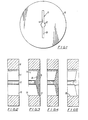
- the die piece 10 is formed with an extrusion aperture 11 comprising a central cylindrical portion 12 from which extend two narrower parallel-sided arm portions 13.
- Figure 1 shows a very simple form of extrusion aperture for the purposes of illustration only and that the principles of the invention are applicable to extrusion apertures of any shape and complexity, including apertures for extruding hollow sections.
- the dimensions of the aperture 11 are calculated in the usual way to allow for shrinkage and deflection of the die material during the extrusion process.
- the aperture will normally be electro- discharge machined in the die piece and then cleaned and polished.
- the die piece 10 is of constant thickness so that, initially, the extrusion aperture is of constant axial bearing depth.
- a suitable compound 14 is forced partly into the extrusion aperture 11 by means of a piston (not shown) which simulates the action of an extrusion press.
- the piston is stopped when the compound 14 is observed approaching the open end or outlet 15 from the aperture.
- a probe may be located within the aperture to detect and indicate when the compound has been injected into the aperture to a predetermined extent.
- the probe may be electrically vibrated, electrical means being provided to detect the change in frequency of vibration of the probe which occurs when it is contacted by the compound.
- the axial deformation of the leading surface of the compound 14 at any location defines the required axial bearing depth for the extrusion aperture at that location. Consequently the line 16 may be regarded as representing the required location of the effective outlet from the extrusion aperture.
- the die may be reshaped simply by removing surface material from the interior of the extrusion aperture in the area between the line 16 and the outlet 15 so as to widen the aperture in that area and thus limit the effective bearing depth of the aperture to the area between the line 16 and the inlet 17.
- the material may be removed in any suitable manner.
- the line 16 could be scribed on the interior surface of the die, the compound removed and the excess material machined away.
- the material is removed by an acid etching process or an electro-etching process.
- the compound 14 may be any appropriate flowable material it is, for the purposes of the acid- etching method to be described, preferably an acid resistant material.
- an acid resistant material for example it may be a viscous acid-resistant printing ink of the kind conventionally used in the production of printed circuit boards.
- the die piece, with the compound 14 still in place may simply be placed in an acid bath, the exterior of the die first having been coated or covered with an acid resistant material.
- the die remains in the acid bath for a period necessary to remove the required amount of material from the interior of the extrusion aperture between the surface of the compound 14 and the outlet 15. Typically material may be removed to a depth of the order of 15 to 20 thousandths of an inch. After the etching has been completed the die piece is removed from the acid bath and the compound 14 is removed.
- the compound 14 In the case where the material is to be removed by an electro-etching method, the compound 14 must be an electrically non-conductive material, such as a non-conductive wax.
- the exterior of the die must also be coated or covered with a non-conductive layer, for example a layer of thin plastics film.
- the die is then immersed in a suitable electrolyte and acts as an anode, a separate cathode also being immersed in the electrolyte.
- the die and cathode remain in the electrolyte, and are subjected to an electric voltage, for a sufficiently long period to remove the required amount of material from the die and deposit it on the cathode.
- the die piece is removed from the electrolyte and the compound 14 is removed.
- the bearing depth is made exactly equal to the displacement of the leading surface of the extrudable material from a fixed datum, it may be preferable in some forms of die for other factors affecting flow to be taken into account by providing some mathematical relation, other than a direct equivalent, between the bearing depth and the corresponding dimension of the deformed material.
Landscapes
- Engineering & Computer Science (AREA)
- Mechanical Engineering (AREA)
- Extrusion Moulding Of Plastics Or The Like (AREA)
- Extrusion Of Metal (AREA)
- Formation And Processing Of Food Products (AREA)
- Diaphragms For Electromechanical Transducers (AREA)
- Press Drives And Press Lines (AREA)
- Acyclic And Carbocyclic Compounds In Medicinal Compositions (AREA)
- Heterocyclic Compounds That Contain Two Or More Ring Oxygen Atoms (AREA)
- Moulds For Moulding Plastics Or The Like (AREA)
- Blow-Moulding Or Thermoforming Of Plastics Or The Like (AREA)
- Heat Sensitive Colour Forming Recording (AREA)
- Reinforced Plastic Materials (AREA)
Priority Applications (1)
| Application Number | Priority Date | Filing Date | Title |
|---|---|---|---|
| AT83302931T ATE28988T1 (de) | 1982-05-25 | 1983-05-23 | Herstellung von strangpressmatrizen. |
Applications Claiming Priority (2)
| Application Number | Priority Date | Filing Date | Title |
|---|---|---|---|
| GB8215216 | 1982-05-25 | ||
| GB8215216 | 1982-05-25 |
Publications (3)
| Publication Number | Publication Date |
|---|---|
| EP0095359A2 true EP0095359A2 (de) | 1983-11-30 |
| EP0095359A3 EP0095359A3 (en) | 1984-07-25 |
| EP0095359B1 EP0095359B1 (de) | 1987-08-19 |
Family
ID=10530605
Family Applications (1)
| Application Number | Title | Priority Date | Filing Date |
|---|---|---|---|
| EP83302931A Expired EP0095359B1 (de) | 1982-05-25 | 1983-05-23 | Herstellung von Strangpressmatrizen |
Country Status (15)
| Country | Link |
|---|---|
| US (1) | US4493229A (de) |
| EP (1) | EP0095359B1 (de) |
| JP (1) | JPS58215216A (de) |
| AT (1) | ATE28988T1 (de) |
| CA (1) | CA1208044A (de) |
| DE (1) | DE3373064D1 (de) |
| DK (1) | DK158714C (de) |
| ES (1) | ES522681A0 (de) |
| FI (1) | FI78629C (de) |
| IL (1) | IL68762A (de) |
| IN (1) | IN159550B (de) |
| NO (1) | NO159146C (de) |
| NZ (1) | NZ204338A (de) |
| PT (1) | PT76740B (de) |
| ZA (1) | ZA833718B (de) |
Cited By (2)
| Publication number | Priority date | Publication date | Assignee | Title |
|---|---|---|---|---|
| EP0159809A1 (de) * | 1984-03-21 | 1985-10-30 | Hobson Process Limited | Verfahren zur Herstellung von Strangpressmatrizen |
| CN102303223A (zh) * | 2011-08-31 | 2012-01-04 | 东睦(江门)粉末冶金有限公司 | 一种下冲模具加工工艺流程 |
Families Citing this family (5)
| Publication number | Priority date | Publication date | Assignee | Title |
|---|---|---|---|---|
| JPH03118941U (de) * | 1990-03-19 | 1991-12-09 | ||
| US5756016A (en) * | 1996-05-13 | 1998-05-26 | Huang; Yean-Jenq | Method for modeling a high speed extrusion die |
| USRE38534E1 (en) | 1996-05-13 | 2004-06-15 | Altech International Limited | Extrusion die |
| WO2001046529A1 (en) | 1999-12-22 | 2001-06-28 | Infiltrator Systems, Inc. | Leaching chamber endplate |
| CN104626502B (zh) * | 2014-12-08 | 2017-03-22 | 宁波新安东橡塑制品有限公司 | 一种密封胶条成型模具及其制造方法 |
Family Cites Families (7)
| Publication number | Priority date | Publication date | Assignee | Title |
|---|---|---|---|---|
| US1789675A (en) * | 1927-02-09 | 1931-01-20 | Ig Farbenindustrie Ag | Die extrusion method and apparatus |
| US2341749A (en) * | 1942-03-14 | 1944-02-15 | Arthur M Webb | Extrusion die |
| US2538918A (en) * | 1944-09-15 | 1951-01-23 | Comptoir Ind Etirage | Die for the extrusion of metals |
| US3359192A (en) * | 1965-03-12 | 1967-12-19 | Balco Filtertechnik Gmbh | Process of manufacturing a sieve plate having apertures of nonuniform crosssection |
| JPS53118261A (en) * | 1977-03-25 | 1978-10-16 | Sumitomo Metal Ind Ltd | Die for use in hot extrusion of non-symmetrical shape steel |
| SU712160A1 (ru) * | 1978-10-02 | 1980-01-30 | Московский Ордена Трудового Красного Знамени Институт Стали И Сплавов | Матрица дл прессовани разнотолщинных профилей |
| JPS5916532B2 (ja) * | 1979-04-23 | 1984-04-16 | 日本軽金属株式会社 | アルミニウム押し出し成形用ダイスにおけるベアリング孔加工方法 |
-
1983
- 1983-05-11 DK DK209583A patent/DK158714C/da not_active IP Right Cessation
- 1983-05-20 FI FI831786A patent/FI78629C/fi not_active IP Right Cessation
- 1983-05-23 AT AT83302931T patent/ATE28988T1/de not_active IP Right Cessation
- 1983-05-23 PT PT76740A patent/PT76740B/pt unknown
- 1983-05-23 EP EP83302931A patent/EP0095359B1/de not_active Expired
- 1983-05-23 DE DE8383302931T patent/DE3373064D1/de not_active Expired
- 1983-05-23 IL IL68762A patent/IL68762A/xx unknown
- 1983-05-24 NZ NZ204338A patent/NZ204338A/en unknown
- 1983-05-24 ES ES522681A patent/ES522681A0/es active Granted
- 1983-05-24 ZA ZA833718A patent/ZA833718B/xx unknown
- 1983-05-24 CA CA000428730A patent/CA1208044A/en not_active Expired
- 1983-05-24 NO NO831824A patent/NO159146C/no unknown
- 1983-05-25 JP JP58092220A patent/JPS58215216A/ja active Granted
- 1983-05-25 IN IN663/CAL/83A patent/IN159550B/en unknown
- 1983-05-25 US US06/498,097 patent/US4493229A/en not_active Expired - Fee Related
Cited By (3)
| Publication number | Priority date | Publication date | Assignee | Title |
|---|---|---|---|---|
| EP0159809A1 (de) * | 1984-03-21 | 1985-10-30 | Hobson Process Limited | Verfahren zur Herstellung von Strangpressmatrizen |
| CN102303223A (zh) * | 2011-08-31 | 2012-01-04 | 东睦(江门)粉末冶金有限公司 | 一种下冲模具加工工艺流程 |
| CN102303223B (zh) * | 2011-08-31 | 2013-04-10 | 东睦(江门)粉末冶金有限公司 | 一种下冲模具加工工艺流程 |
Also Published As
| Publication number | Publication date |
|---|---|
| FI831786A0 (fi) | 1983-05-20 |
| IL68762A (en) | 1985-12-31 |
| FI831786L (fi) | 1983-11-26 |
| DK158714C (da) | 1991-01-07 |
| JPS58215216A (ja) | 1983-12-14 |
| EP0095359B1 (de) | 1987-08-19 |
| JPS6358056B2 (de) | 1988-11-14 |
| IN159550B (de) | 1987-05-23 |
| ES8403754A1 (es) | 1984-04-16 |
| ZA833718B (en) | 1984-01-25 |
| FI78629B (fi) | 1989-05-31 |
| DK158714B (da) | 1990-07-09 |
| NO159146C (no) | 1988-12-07 |
| ATE28988T1 (de) | 1987-09-15 |
| DK209583D0 (da) | 1983-05-11 |
| PT76740A (en) | 1983-06-01 |
| IL68762A0 (en) | 1983-09-30 |
| DK209583A (da) | 1983-11-26 |
| NZ204338A (en) | 1986-01-24 |
| NO831824L (no) | 1983-11-28 |
| ES522681A0 (es) | 1984-04-16 |
| EP0095359A3 (en) | 1984-07-25 |
| CA1208044A (en) | 1986-07-22 |
| DE3373064D1 (en) | 1987-09-24 |
| US4493229A (en) | 1985-01-15 |
| PT76740B (en) | 1986-01-27 |
| FI78629C (fi) | 1989-09-11 |
| NO159146B (no) | 1988-08-29 |
Similar Documents
| Publication | Publication Date | Title |
|---|---|---|
| US4493229A (en) | Forming of extrusion dies | |
| EP0563616B1 (de) | Vorrichtung zur feinelektrochemischen Bearbeitung | |
| US2785280A (en) | Printed electric circuits and electric circuit components | |
| CN113781508A (zh) | 叶型孔图像的轮廓型线提取与分割方法及系统、设备、存储介质 | |
| US4045312A (en) | Method for the electrolytic etching of metal workpiece | |
| JPH0692053A (ja) | 印刷用メタルマスク版の製造方法 | |
| EP2044242B1 (de) | Vorrichtung für die elektrochemische bearbeitung eines gegenstandes sowie ein verfahren zur herstellung der vorrichtung, ein verfahren für die elektrochemische bearbeitung eines gegenstandes, verwendung der vorrichtung sowie ein durch solch ein verfahren hergestellte gegenstand | |
| EP0869859B1 (de) | Vorrichtung zum elektrochemischen bearbeiten von werkstücken | |
| EP0159809A1 (de) | Verfahren zur Herstellung von Strangpressmatrizen | |
| US2225733A (en) | Process for the electrolytic production of metal screens | |
| US5259920A (en) | Manufacturing method, including etch-rate monitoring | |
| US3513282A (en) | Electrode for spark erosion apparatus | |
| SU1060383A1 (ru) | Способ электроэрозионного изготовлени рабочих элементов вырубных штампов | |
| JPH0957363A (ja) | 精密プレス金型 | |
| JP3141118B2 (ja) | 印刷用メタルマスク版の製造方法 | |
| CN112605159A (zh) | 一种导向器叶片封严槽集成电极校正装置 | |
| US4937415A (en) | Examination slide grid system | |
| CN112584614A (zh) | 埋阻电路板的制作方法及埋阻电路板 | |
| WO2001004384A1 (de) | Verfahren zur herstellung von mikrostanzwerkzeugen | |
| SU1456768A2 (ru) | Способ изготовлени датчиков методом гальванического меднени дл контрол циклических деформаций | |
| KR0151002B1 (ko) | 리이드 프레임 제조방법 및 그 장치 | |
| CN114752986A (zh) | 一种电镀工具的参数调整方法及电镀方法 | |
| RU25706U1 (ru) | Устройство для электрохимического прошивания | |
| JPS6315992B2 (de) | ||
| JPS6347346B2 (de) |
Legal Events
| Date | Code | Title | Description |
|---|---|---|---|
| PUAI | Public reference made under article 153(3) epc to a published international application that has entered the european phase |
Free format text: ORIGINAL CODE: 0009012 |
|
| AK | Designated contracting states |
Designated state(s): AT BE CH DE FR GB IT LI LU NL SE |
|
| 17P | Request for examination filed |
Effective date: 19840125 |
|
| PUAL | Search report despatched |
Free format text: ORIGINAL CODE: 0009013 |
|
| AK | Designated contracting states |
Designated state(s): AT BE CH DE FR GB IT LI LU NL SE |
|
| RAP1 | Party data changed (applicant data changed or rights of an application transferred) |
Owner name: HOBSON PROCESS LIMITED |
|
| GRAA | (expected) grant |
Free format text: ORIGINAL CODE: 0009210 |
|
| AK | Designated contracting states |
Kind code of ref document: B1 Designated state(s): AT BE CH DE FR GB IT LI LU NL SE |
|
| REF | Corresponds to: |
Ref document number: 28988 Country of ref document: AT Date of ref document: 19870915 Kind code of ref document: T |
|
| ET | Fr: translation filed | ||
| REF | Corresponds to: |
Ref document number: 3373064 Country of ref document: DE Date of ref document: 19870924 |
|
| ITF | It: translation for a ep patent filed | ||
| PG25 | Lapsed in a contracting state [announced via postgrant information from national office to epo] |
Ref country code: LU Free format text: LAPSE BECAUSE OF NON-PAYMENT OF DUE FEES Effective date: 19880531 |
|
| PLBE | No opposition filed within time limit |
Free format text: ORIGINAL CODE: 0009261 |
|
| STAA | Information on the status of an ep patent application or granted ep patent |
Free format text: STATUS: NO OPPOSITION FILED WITHIN TIME LIMIT |
|
| 26N | No opposition filed | ||
| PGFP | Annual fee paid to national office [announced via postgrant information from national office to epo] |
Ref country code: FR Payment date: 19900510 Year of fee payment: 8 |
|
| PGFP | Annual fee paid to national office [announced via postgrant information from national office to epo] |
Ref country code: SE Payment date: 19900511 Year of fee payment: 8 Ref country code: GB Payment date: 19900511 Year of fee payment: 8 |
|
| PGFP | Annual fee paid to national office [announced via postgrant information from national office to epo] |
Ref country code: AT Payment date: 19900515 Year of fee payment: 8 |
|
| PGFP | Annual fee paid to national office [announced via postgrant information from national office to epo] |
Ref country code: CH Payment date: 19900528 Year of fee payment: 8 |
|
| ITTA | It: last paid annual fee | ||
| PGFP | Annual fee paid to national office [announced via postgrant information from national office to epo] |
Ref country code: NL Payment date: 19900531 Year of fee payment: 8 |
|
| PGFP | Annual fee paid to national office [announced via postgrant information from national office to epo] |
Ref country code: BE Payment date: 19900601 Year of fee payment: 8 |
|
| PGFP | Annual fee paid to national office [announced via postgrant information from national office to epo] |
Ref country code: LU Payment date: 19900611 Year of fee payment: 8 |
|
| PGFP | Annual fee paid to national office [announced via postgrant information from national office to epo] |
Ref country code: DE Payment date: 19900629 Year of fee payment: 8 |
|
| PG25 | Lapsed in a contracting state [announced via postgrant information from national office to epo] |
Ref country code: GB Effective date: 19910523 Ref country code: AT Effective date: 19910523 |
|
| PG25 | Lapsed in a contracting state [announced via postgrant information from national office to epo] |
Ref country code: SE Effective date: 19910524 |
|
| PG25 | Lapsed in a contracting state [announced via postgrant information from national office to epo] |
Ref country code: LI Effective date: 19910531 Ref country code: CH Effective date: 19910531 Ref country code: BE Effective date: 19910531 |
|
| BERE | Be: lapsed |
Owner name: HOBSON PROCESS LTD Effective date: 19910531 |
|
| PG25 | Lapsed in a contracting state [announced via postgrant information from national office to epo] |
Ref country code: NL Effective date: 19911201 |
|
| NLV4 | Nl: lapsed or anulled due to non-payment of the annual fee | ||
| GBPC | Gb: european patent ceased through non-payment of renewal fee | ||
| PG25 | Lapsed in a contracting state [announced via postgrant information from national office to epo] |
Ref country code: FR Effective date: 19920131 |
|
| REG | Reference to a national code |
Ref country code: CH Ref legal event code: PL |
|
| PG25 | Lapsed in a contracting state [announced via postgrant information from national office to epo] |
Ref country code: DE Effective date: 19920303 |
|
| REG | Reference to a national code |
Ref country code: FR Ref legal event code: ST |
|
| EUG | Se: european patent has lapsed |
Ref document number: 83302931.7 Effective date: 19911209 |