EP0095655B1 - Gerät und Verfahren zur Bestimmung therapeutischer Mittel - Google Patents
Gerät und Verfahren zur Bestimmung therapeutischer Mittel Download PDFInfo
- Publication number
- EP0095655B1 EP0095655B1 EP83104886A EP83104886A EP0095655B1 EP 0095655 B1 EP0095655 B1 EP 0095655B1 EP 83104886 A EP83104886 A EP 83104886A EP 83104886 A EP83104886 A EP 83104886A EP 0095655 B1 EP0095655 B1 EP 0095655B1
- Authority
- EP
- European Patent Office
- Prior art keywords
- capillary tube
- reagent
- undersurface
- container
- base
- Prior art date
- Legal status (The legal status is an assumption and is not a legal conclusion. Google has not performed a legal analysis and makes no representation as to the accuracy of the status listed.)
- Expired
Links
Images


Classifications
-
- B—PERFORMING OPERATIONS; TRANSPORTING
- B01—PHYSICAL OR CHEMICAL PROCESSES OR APPARATUS IN GENERAL
- B01L—CHEMICAL OR PHYSICAL LABORATORY APPARATUS FOR GENERAL USE
- B01L3/00—Containers or dishes for laboratory use, e.g. laboratory glassware; Droppers
- B01L3/50—Containers for the purpose of retaining a material to be analysed, e.g. test tubes
- B01L3/508—Rigid containers without fluid transport within
- B01L3/5082—Test tubes per se
-
- B—PERFORMING OPERATIONS; TRANSPORTING
- B01—PHYSICAL OR CHEMICAL PROCESSES OR APPARATUS IN GENERAL
- B01L—CHEMICAL OR PHYSICAL LABORATORY APPARATUS FOR GENERAL USE
- B01L3/00—Containers or dishes for laboratory use, e.g. laboratory glassware; Droppers
- B01L3/02—Burettes; Pipettes
- B01L3/021—Pipettes, i.e. with only one conduit for withdrawing and redistributing liquids
-
- G—PHYSICS
- G01—MEASURING; TESTING
- G01N—INVESTIGATING OR ANALYSING MATERIALS BY DETERMINING THEIR CHEMICAL OR PHYSICAL PROPERTIES
- G01N33/00—Investigating or analysing materials by specific methods not covered by groups G01N1/00 - G01N31/00
- G01N33/48—Biological material, e.g. blood, urine; Haemocytometers
- G01N33/50—Chemical analysis of biological material, e.g. blood, urine; Testing involving biospecific ligand binding methods; Immunological testing
- G01N33/52—Use of compounds or compositions for colorimetric, spectrophotometric or fluorometric investigation, e.g. use of reagent paper and including single- and multilayer analytical elements
- G01N33/528—Atypical element structures, e.g. gloves, rods, tampons, toilet paper
-
- G—PHYSICS
- G01—MEASURING; TESTING
- G01N—INVESTIGATING OR ANALYSING MATERIALS BY DETERMINING THEIR CHEMICAL OR PHYSICAL PROPERTIES
- G01N33/00—Investigating or analysing materials by specific methods not covered by groups G01N1/00 - G01N31/00
- G01N33/48—Biological material, e.g. blood, urine; Haemocytometers
- G01N33/50—Chemical analysis of biological material, e.g. blood, urine; Testing involving biospecific ligand binding methods; Immunological testing
- G01N33/53—Immunoassay; Biospecific binding assay; Materials therefor
- G01N33/5302—Apparatus specially adapted for immunological test procedures
- G01N33/5304—Reaction vessels, e.g. agglutination plates
-
- Y—GENERAL TAGGING OF NEW TECHNOLOGICAL DEVELOPMENTS; GENERAL TAGGING OF CROSS-SECTIONAL TECHNOLOGIES SPANNING OVER SEVERAL SECTIONS OF THE IPC; TECHNICAL SUBJECTS COVERED BY FORMER USPC CROSS-REFERENCE ART COLLECTIONS [XRACs] AND DIGESTS
- Y10—TECHNICAL SUBJECTS COVERED BY FORMER USPC
- Y10S—TECHNICAL SUBJECTS COVERED BY FORMER USPC CROSS-REFERENCE ART COLLECTIONS [XRACs] AND DIGESTS
- Y10S436/00—Chemistry: analytical and immunological testing
- Y10S436/807—Apparatus included in process claim, e.g. physical support structures
-
- Y—GENERAL TAGGING OF NEW TECHNOLOGICAL DEVELOPMENTS; GENERAL TAGGING OF CROSS-SECTIONAL TECHNOLOGIES SPANNING OVER SEVERAL SECTIONS OF THE IPC; TECHNICAL SUBJECTS COVERED BY FORMER USPC CROSS-REFERENCE ART COLLECTIONS [XRACs] AND DIGESTS
- Y10—TECHNICAL SUBJECTS COVERED BY FORMER USPC
- Y10S—TECHNICAL SUBJECTS COVERED BY FORMER USPC CROSS-REFERENCE ART COLLECTIONS [XRACs] AND DIGESTS
- Y10S436/00—Chemistry: analytical and immunological testing
- Y10S436/807—Apparatus included in process claim, e.g. physical support structures
- Y10S436/81—Tube, bottle, or dipstick
-
- Y—GENERAL TAGGING OF NEW TECHNOLOGICAL DEVELOPMENTS; GENERAL TAGGING OF CROSS-SECTIONAL TECHNOLOGIES SPANNING OVER SEVERAL SECTIONS OF THE IPC; TECHNICAL SUBJECTS COVERED BY FORMER USPC CROSS-REFERENCE ART COLLECTIONS [XRACs] AND DIGESTS
- Y10—TECHNICAL SUBJECTS COVERED BY FORMER USPC
- Y10T—TECHNICAL SUBJECTS COVERED BY FORMER US CLASSIFICATION
- Y10T436/00—Chemistry: analytical and immunological testing
- Y10T436/25—Chemistry: analytical and immunological testing including sample preparation
- Y10T436/2575—Volumetric liquid transfer
Definitions
- This invention relates to assay methods and particularly to precisely measured fluid transfer and mixing, in a two-fluid reagent assay.
- the device used for effecting the fluid transfer is a capillary tube holder and capillary tube which transfers precisely measured reaction product from one liquid reagent container to a second container with a second reagent, and therein mixing the contents of the capillary tube with the second reagent within a definite critical mixing period.
- the use of a two-liquid reagent method in which the first reagent is reacted with blood serum/plasma and the reaction product then transferred to a second reagent for further reaction, the so-resulting product then being analyzed for a given ligand by a fluorometer is not new, and is known to the art.
- the two separate reagents are equally known, the first reagent being generally describable as a fluorogenic drug, the contents of the second reagent being generically known as an antibody enzyme. It should be understood that the composition of the two reagents and the procedure in use of two such independent reagents is not part of the present invention, but the immuno-assay method so described, is improved by the present invention.
- the improved procedures of the present invention lie in the methods of transferring fluid consisting of the reaction product of a first reagent and patient specimen e.g. serum or plasma, to the container of a second reagent and then thoroughly mixing an accurately measured amount of such reaction product with the second reagent, all of which is carried out within the limits of a narrowly defined time span and by means of a unique capillary tube and capillary tube holder device.
- a first reagent and patient specimen e.g. serum or plasma
- the accuracy of the assay depends upon the transfer in a defined manner of a precisely measured amount of reaction product of patient specimen and fluorogenic drug reagent in the first'container, to a second container which contains antibody reagent.
- This is accomplished by using an accurately calibrated bore of a precisely measured length of capillary tube held so that its free ends are at no time in contact with any other body.
- the capillary tube is filled by inserting only the tip of the capillary into a small globule of product which appears through a small orifice of the first container when the container or cuvette is tipped, bringing the small orifice below the liquid level in the first container.
- the capillary tube and its holder are then transferred to the container for the second reagent.
- the capillary tube is inserted into the second cuvette through an access opening which is then sealed by the undersurface of the capillary tube holder.
- the capillary tube is held in a suspended position over the level of the liquid reagent.
- the capillary tube is suspended by means of a standard which projects perpendicularly from the base and is integrally related to the base.
- a sleeve at the distal end of the standard has a narrow slit which provides an interference fit with the capillary tube. The sleeve grips the capillary tube at a location intermediate the capillary tube open ends.
- the contents of the capillary tube are then homogeneously mixed with the liquid second reagent by vigorously agitating the container in an up-and-down manner causing discharge of the capillary tube contents simultaneously with the second reagent washing over both ends of the capillary tube which were heretofore suspended above the liquid level. Both the capillary tube discharge and the mixing occur within a narrowly defined time limit with the result that the capillary tube content is uniformly dispersed through the second reagent before their interaction is complete. Thereafter the second container together with the second reagent reaction product are fitted into a fluorometer and the assay results provided in either printed or display alphanumeric form.
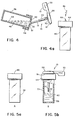
- Figure 4a illustrates a second cuvette with a
- Figure 5a illustrates the first cuvette ("A") and Figure 5b is the second cuvette (“B") and a capillary tube suspended within the second cuvette ("B") above the liquid level of the second reagent;
- Figure 6 illustrates the mixing step wherein the contents of the capillary tube in Figure 5b are mixed with the liquid reagent of cuvette ("B") to produce a reaction product which is then measured by a therapeutic drug assay utilizing a fluorescence intensity measuring device;
- Figure 7 illustrates in schematic form a top view of a fluorometer.
- Liquid transfer in the present invention between the two liquid reagent containers, is illustrated in Figures 1-4.
- the transfer is by means of a capillary tube holder designated generally by reference numeral 10 and a capillary tube 12 which has an accurately calibrated bore 14 and is of a precise measured length in order to transfer an accurately defined volume of liquid which fills the capillary tube 12 by capillary action.
- the plastic composition holder for the capillary tube 12 consists of a base 13 and integrally related handle 33 with the base 13 having a recess 15 (Fig. 2) and a sealing washer 16 press fitted with the recess 15 and permanently held therein.
- a standard 20 terminating in a sleeve 24 with a longitudinal slit 26 enabling an interference fit with capillary tube 12 (Fig. 2a).
- Sleeve 24 encircles the major portion of the capillary tube 12 when the capillary tube is snap fitted in place.
- a marker 28 on the standard 20 defines the position for the proximal end 30 of the capillary tube so that the proximal end 30 and distal end 32 are accurately defined in position relative to the holder 10 and are further held so that the two open ends 30, 32 are unengaged by either the holder 10, or by any other structure during fluid transfer and mixing procedures.
- composition of the plastic material composing the holder 10 can vary, of course, with design preference, typically the base 13 integrally related handle 33 and standard 20 consist of Delrin@ (Polymethleneoxide).
- the washer 16, while similarly selectable, as a matter of design preference may typically consist of a about a 70 durometer urethane material. Mention of these two compositions is only by way of illustration and is not intended to be a limitation of the invention.
- capillary tube holder can be made by any conventional means such as insert molding or the like.
- the immuno assay procedure contemplates two cuvettes, 38 and 40 ( Figures 5a and 5b) also labeled "A" (cuvette 38) and "B” (cuvette 40).
- Cuvette 38 may if preferred have indented sides although not shown as such in Figures 3, 4, and 5.
- the purpose of having two differently shaped cuvettes is to maintain them readily distinguishable as can also be done by color coding the sealing covers 42 and 44.
- Each cuvette cover has a spike 46 which normally seals an access opening in the cover.
- the spike is not broken off until the appropriate stage of the assay. It should be noted that the spike has already been broken away in cuvette 38 ( Figures 3, 4 and 5).
- Cuvette 38 contains a fluorogenic drug reagent which is in liquid form and designated by reference numeral 48.
- blood is first obtained from the donor, i.e. the patient whose assay is in question.
- the procedure is outlined in U.S. Patent No. 3,992,150 (supra).
- the blood sample is centrifuged in a known manner which separates the serum/plasma from the blood cells and the serum/plasma received in a capillary (not shown) which is dropped through access opening 50 of cover 42 on cuvette 38 and into the fluorogenic drug reagent 48.
- the serum/ plasma and reagent 48 are thoroughly mixed after putting an adhesive seal over opening 50 to retain the contents of cuvette 38 during mixing.
- the reaction product from cuvette 38 is then transferred to cuvette 40 by means of the capillary tube holder 10 and capillary tube 12 ( Figure 4).
- the access opening 50 is brought below fluid level 52.
- the dimension of the access opening 50 is sufficiently small so that liquid will not "pour” through the opening, instead there will be generated a globule 51 of fluid extending at least partially through the access opening 50.
- the very tip distal end of capillary tube 12 is carefully applied against the globule 51 of extending fluid, all of which occurs without touching the edges of the opening 50 or any other portion of the cover 42.
- the capillary tube is filled from distal end 32 to proximal end 30. Since the bore 14 is accurately calibrated and the length of the capillary tube accurately measured, a precise quantity of the reaction product is obtained.
- the spike 46 on cover 44 of cuvette 40 is broken away and distal end 32 of the capillary tube is carefully inserted through the access opening again without touching either the side of the opening or the inner walls of cuvette 40.
- the end 32 of the capillary tube is suspended above the liquid level 54 of the second reagent 56.
- the composition of the reagent 56 is no part of the present invention but for illustration purposes the composition may be an antibody enzyme.
- a thorough mixing of the capillary tube contents occurs within a short period of time throughout the body of the liquid reagent 56, i.e., within a time period of about 1 to 5 seconds.
- the contents of the capillary tube 12 thoroughly and homogeneously disperse within reagent 56 and the two liquids are reacted.
- the reaction product obtained, in the manner so described, together with the cuvette 40 is next mounted within a fluorometer designated generally by reference numeral 60 ( Figure 7) where a light source 62 produces light passed through filter 70, lens 72 and aperture 75 of shutter 77. After passing through cuvette 40, the remaining light energy is trapped by a light trap 74 which limits the diffusion of light essentially to the path described.
- the fluorophores within the cuvette 40 emit at 450 nanometers and light from source 62 emits at 405 nanometers.
- the fluoroescence from the fluorophores in cuvette 40 is directed transversely to the path of light developed from light source 62.
- the fluorescence is filtered through a filter 76 and then to a photomultiplier 78.
- the light intensity is transduced to an electrical signal output with a value correlated to the fluorescence intensity, hence directly related to the ligand in cuvette 40.
- the present invention is further useful in that this scheme of light analysis is unimpeded by the presence of a capillary tube, i.e., in prior practice when transferring fluid from cuvette 38 to cuvette 40 the calibrated capillary tube was simply dropped into cuvette 40 and unless displaced out of a light impeding position would interfere with the accuracy of the assay.
- Such problem is wholly obviated in the present invention for reasons described.
- the intensity of fluorescent light processed as described is transduced into a voltage which is "read" either as a printed value or an alphanumerical display. The readout provides a measure of drug concentration in the blood, thus enabling a more accurate prescription of amount of drug which should be administered to obtain the acceptable or preferred level of drug concentration in the blood of a patient.
- the procedure described is readily applicable for therapeutic drug assay in a wide spectrum of drugs which includes, but is not limited to, assays for gentamicin, sisomicin, netilmicin, tobramycin, kanamycin, amikacin, diphenylhyantoin, pheno- barbital, theophylline, carbamazepine, primidone, quindine, and others.
- the described capillary tube, and capillary tube holder represent a cost effective, accurate and precise transfer method between the two liquid reagents in a two-liquid reactent immuno assay method employing fluorescence intensity as the parameter in a method of assaying therapeutic drugs in a patient's blood stream.
- the described method enables virtually instantaneous mixing of the fluorogenic drug reagent-and-serum with antibody enzyme reagent in a second cuvette. Because the capillary tubes, cuvettes and capillary tube holder are disposable, there is no required maintenance, and no upkeep. Moreover, the capillary tubes do not require calibration and form an accurate and precise method for dispensing fluids in an accurate manner. Since the volumes transferred are small, change in temperature of the materials in the cuvettes are minimal and acceptable.
Landscapes
- Health & Medical Sciences (AREA)
- Chemical & Material Sciences (AREA)
- Life Sciences & Earth Sciences (AREA)
- Immunology (AREA)
- Hematology (AREA)
- Engineering & Computer Science (AREA)
- Urology & Nephrology (AREA)
- Biomedical Technology (AREA)
- Molecular Biology (AREA)
- Chemical Kinetics & Catalysis (AREA)
- General Health & Medical Sciences (AREA)
- Analytical Chemistry (AREA)
- Physics & Mathematics (AREA)
- Food Science & Technology (AREA)
- Medicinal Chemistry (AREA)
- Biotechnology (AREA)
- Microbiology (AREA)
- Biochemistry (AREA)
- Cell Biology (AREA)
- General Physics & Mathematics (AREA)
- Pathology (AREA)
- Clinical Laboratory Science (AREA)
- Investigating Or Analysing Biological Materials (AREA)
- Investigating Or Analysing Materials By The Use Of Chemical Reactions (AREA)
- Automatic Analysis And Handling Materials Therefor (AREA)
Claims (6)
Applications Claiming Priority (2)
| Application Number | Priority Date | Filing Date | Title |
|---|---|---|---|
| US383826 | 1982-06-01 | ||
| US06/383,826 US4454235A (en) | 1982-06-01 | 1982-06-01 | Capillary tube holder for liquid transfer in immunoassay |
Publications (2)
| Publication Number | Publication Date |
|---|---|
| EP0095655A1 EP0095655A1 (de) | 1983-12-07 |
| EP0095655B1 true EP0095655B1 (de) | 1985-11-06 |
Family
ID=23514877
Family Applications (1)
| Application Number | Title | Priority Date | Filing Date |
|---|---|---|---|
| EP83104886A Expired EP0095655B1 (de) | 1982-06-01 | 1983-05-18 | Gerät und Verfahren zur Bestimmung therapeutischer Mittel |
Country Status (8)
| Country | Link |
|---|---|
| US (1) | US4454235A (de) |
| EP (1) | EP0095655B1 (de) |
| JP (1) | JPS58215559A (de) |
| AU (1) | AU544440B2 (de) |
| CA (1) | CA1197775A (de) |
| DE (1) | DE3361163D1 (de) |
| ES (1) | ES522918A0 (de) |
| IL (1) | IL68262A (de) |
Families Citing this family (36)
| Publication number | Priority date | Publication date | Assignee | Title |
|---|---|---|---|---|
| GB2121962B (en) * | 1982-06-08 | 1985-10-02 | Serono Diagnostics Ltd | Manual immunoassays and apparatus therefor |
| JPS6270763A (ja) * | 1985-06-05 | 1987-04-01 | シンビオテイツクス コ−ポレイシヨン | 免疫アツセイインキユベ−シヨン装置 |
| US5501949A (en) * | 1985-12-10 | 1996-03-26 | Murex Diagnostics Corporation | Particle bound binding component immunoassay |
| IT206959Z2 (it) * | 1986-04-16 | 1987-10-26 | Sta Te Srl | Dispositivo usa e getta per la raccolta di campioni fisiologici, in particolare campioni corpologici. |
| DE9203973U1 (de) * | 1992-03-25 | 1993-02-11 | Gundelsheimer, Peter H., 6760 Rockenhausen | Laborröhrchen für die Dosierung von Flüssigkeiten |
| US5637467A (en) * | 1992-10-13 | 1997-06-10 | Behringwerke Ag | Heterogeneous assay using a pendulous drop |
| US5403551A (en) * | 1993-09-16 | 1995-04-04 | Roche Diagnostic Systems, Inc. | Assaying device and container for in field analysis of a specimen and later shipment of the unadulterated specimen |
| DE19624687A1 (de) * | 1996-06-20 | 1998-01-29 | Hamilton Bonaduz Ag | Verfahren zur Durchführung chemischer, insbesondere biochemischer Reaktionen und Pipettierspitze, ggf. mit Reaktionsgefäß |
| ATE224536T1 (de) * | 1997-01-13 | 2002-10-15 | Daniel Dr Studer | Probenhalter für wasserhaltige proben sowie verfahren zu deren verwendung |
| US6514461B1 (en) * | 1997-02-14 | 2003-02-04 | Escreen, Inc. | System for automatically testing a fluid specimen |
| US6342183B1 (en) | 1997-02-14 | 2002-01-29 | Escreen | System for collecting and locally analyzing a fluid specimen |
| JP2003507715A (ja) * | 1999-08-13 | 2003-02-25 | カーティージャン テクノロジーズ、 インコーポレイテッド | 液体試料取扱い装置 |
| US7410807B2 (en) * | 2000-07-24 | 2008-08-12 | D Aurora Vito J | Pregnancy and sex identification test based on saliva or other bodily fluids |
| AU2001296452A1 (en) * | 2000-10-02 | 2002-04-15 | Cryo-Cell International, Inc | Segmented vial assembly and related storage and retrieval method |
| GB201005191D0 (en) | 2010-03-26 | 2010-05-12 | Cambridge Entpr Ltd | Immunoassays,methods for carrying out immunoassays,immunoassay kits and method for manufacturing immunoassay kits |
| US9522396B2 (en) | 2010-12-29 | 2016-12-20 | S.D. Sight Diagnostics Ltd. | Apparatus and method for automatic detection of pathogens |
| WO2013098821A1 (en) | 2011-12-29 | 2013-07-04 | Parasight Ltd. | Methods and systems for detecting a pathogen in a biological sample |
| WO2014188405A1 (en) | 2013-05-23 | 2014-11-27 | Parasight Ltd. | Method and system for imaging a cell sample |
| IL227276A0 (en) | 2013-07-01 | 2014-03-06 | Parasight Ltd | A method and system for preparing a monolayer of cells, particularly suitable for diagnosis |
| WO2015012390A1 (ja) * | 2013-07-26 | 2015-01-29 | 積水メディカル株式会社 | 検体調製用容器 |
| EP3039477B1 (de) | 2013-08-26 | 2021-10-20 | S.D. Sight Diagnostics Ltd. | Digitale mikroskopiesysteme, verfahren und computerprogrammprodukte |
| US10482595B2 (en) | 2014-08-27 | 2019-11-19 | S.D. Sight Diagnostics Ltd. | System and method for calculating focus variation for a digital microscope |
| EP3859425B1 (de) | 2015-09-17 | 2024-04-17 | S.D. Sight Diagnostics Ltd. | Verfahren und vorrichtung zur detektion einer entität in einer körperprobe |
| CA3290154A1 (en) | 2016-01-29 | 2025-11-29 | Purigen Biosystems, Inc. | Isotachophoresis for purification of nucleic acids |
| CA3018536A1 (en) | 2016-03-30 | 2017-10-05 | S.D. Sight Diagnostics Ltd | Distinguishing between blood sample components |
| EP3455626B1 (de) | 2016-05-11 | 2025-08-06 | S.D. Sight Diagnostics Ltd. | Durchführung optischer messungen auf einer probe |
| EP4177593A1 (de) | 2016-05-11 | 2023-05-10 | S.D. Sight Diagnostics Ltd. | Probenträger für optische messungen |
| CN115569515A (zh) | 2017-08-02 | 2023-01-06 | 普瑞珍生物系统公司 | 用于等速电泳的系统、设备和方法 |
| JP6785989B2 (ja) * | 2017-10-10 | 2020-11-18 | 株式会社日立ハイテク | 自動分析装置 |
| CN111788471B (zh) | 2017-11-14 | 2023-12-12 | 思迪赛特诊断有限公司 | 用于光学测量的样品载体 |
| WO2020041283A1 (en) * | 2018-08-21 | 2020-02-27 | Battelle Memorial Institute A Non-Profit Corporation Of The State Of Ohio | Particle sample preparation with filtration |
| MX2022004703A (es) | 2019-10-22 | 2022-05-11 | S D Sight Diagnostics Ltd | Contabilidad de errores en mediciones opticas. |
| BR112022011233A2 (pt) | 2019-12-12 | 2022-08-30 | S D Sight Diagnostics Ltd | Detecção de plaquetas em uma amostra sanguínea |
| CA3160702A1 (en) | 2019-12-12 | 2021-06-17 | S.D. Sight Diagnostics Ltd | Artificial generation of a color blood smear image |
| EP4073492A1 (de) | 2019-12-12 | 2022-10-19 | S.D. Sight Diagnostics Ltd. | Analyse eines analyten in einem medium |
| DE102021122449A1 (de) * | 2021-08-31 | 2023-03-02 | Alfred-Wegener-Institut, Helmholtz-Zentrum für Polar- und Meeresforschung, Stiftung des öffentlichen Rechts | Halter für ein Kapillarröhrchen und Sammelvorrichtung für mehrere Halter |
Family Cites Families (11)
| Publication number | Priority date | Publication date | Assignee | Title |
|---|---|---|---|---|
| US3105618A (en) * | 1960-09-21 | 1963-10-01 | Beckman Instruments Inc | Micro pipette fluid distributor |
| FR1404672A (fr) * | 1964-04-17 | 1965-07-02 | Bouchage Mecanique | Bouchon étaleur à pipette |
| US3525264A (en) * | 1968-04-05 | 1970-08-25 | Becton Dickinson Co | Micropipette holder |
| US3676076A (en) * | 1970-09-24 | 1972-07-11 | Gradko Glass Lab Inc | Disposable container |
| US3811326A (en) * | 1972-02-10 | 1974-05-21 | V Sokol | Disposable dilution system |
| DE2422260B2 (de) * | 1974-05-08 | 1979-04-12 | Compur-Electronic Gmbh, 8000 Muenchen | Einrichtung zur Herstellung einer optisch zu untersuchenden Meßflüssigkeit |
| DE2553613C3 (de) * | 1975-11-28 | 1978-11-23 | Compur-Electronic Gmbh, 8000 Muenchen | Verfahren zur Vorbereitung von Meßflüssigkeiten |
| US4116638A (en) * | 1977-03-03 | 1978-09-26 | Warner-Lambert Company | Immunoassay device |
| DE2721942C3 (de) * | 1977-05-14 | 1980-02-07 | Bayer Ag, 5090 Leverkusen | Vorrichtung zum Aufbereiten einer Meßflüssigkeit zum Einsatz in analytisch optischen Geräten |
| US4279992A (en) * | 1978-03-13 | 1981-07-21 | Miles Laboratories, Inc. | Specific binding assay employing an enzyme-cleavable substrate as label |
| US4214874A (en) * | 1979-02-08 | 1980-07-29 | American Hospital Supply Corporation | Combination and method for mixing the contents of a blood collection tube and thereafter removing the mixing element |
-
1982
- 1982-06-01 US US06/383,826 patent/US4454235A/en not_active Expired - Fee Related
-
1983
- 1983-03-28 IL IL8368262A patent/IL68262A/xx unknown
- 1983-03-31 CA CA000425035A patent/CA1197775A/en not_active Expired
- 1983-04-08 AU AU13262/83A patent/AU544440B2/en not_active Ceased
- 1983-05-18 DE DE8383104886T patent/DE3361163D1/de not_active Expired
- 1983-05-18 EP EP83104886A patent/EP0095655B1/de not_active Expired
- 1983-05-18 JP JP58085996A patent/JPS58215559A/ja active Pending
- 1983-06-01 ES ES522918A patent/ES522918A0/es active Granted
Also Published As
| Publication number | Publication date |
|---|---|
| ES8405950A1 (es) | 1984-06-16 |
| CA1197775A (en) | 1985-12-10 |
| AU544440B2 (en) | 1985-05-30 |
| IL68262A0 (en) | 1983-06-15 |
| DE3361163D1 (en) | 1985-12-12 |
| ES522918A0 (es) | 1984-06-16 |
| AU1326283A (en) | 1983-12-15 |
| IL68262A (en) | 1986-01-31 |
| EP0095655A1 (de) | 1983-12-07 |
| US4454235A (en) | 1984-06-12 |
| JPS58215559A (ja) | 1983-12-15 |
Similar Documents
| Publication | Publication Date | Title |
|---|---|---|
| US4454235A (en) | Capillary tube holder for liquid transfer in immunoassay | |
| EP3145634B1 (de) | Abtastungs- und testsatz, probenhalter und verfahren | |
| EP0163826B1 (de) | Vorrichtung zur Entfernung von Flüssigkeit von der Aussenfläche eines Pipettenrohrs | |
| EP0425604B1 (de) | Analytisches element | |
| AU605257B2 (en) | Self-contained immunoassay element | |
| CN1849515B (zh) | 用于自动测定的检测盒和使用该检测盒的测定装置 | |
| US4883763A (en) | Sample processor card for centrifuge | |
| US4608231A (en) | Self-contained reagent package device for an assay | |
| IE43188B1 (en) | Capillary sampling optical cuvette | |
| CN101384905B (zh) | 盒、残液去除方法以及自动分析装置 | |
| JPS5844349A (ja) | カツプ状容器及び反応トレイ | |
| JPH03181853A (ja) | 酵素免疫測定用カートリツジ、それを用いた測定方法及び測定装置 | |
| JPH04315946A (ja) | 試料を多数のアリコットに分画する装置 | |
| US5139742A (en) | Disposable liquid testing device | |
| JP4339879B2 (ja) | 一体化した液体区画を有するサンプル採取・計量デバイス | |
| US9383298B2 (en) | Method for preparing a sample for analysis | |
| US4676656A (en) | Fluid handling apparatus and method | |
| EP0412225A1 (de) | Vorrichtung zur Messung durch Verschiebung einer genauen Mikrodosis von einer zu analysierenden Flüssigkeit aus einem an einem Ende verschlossenen, gänzlich gefüllten Kapillarröhrchen und Verdrängung dieser Dosis in eine Küvette mittels einer genauen Menge einer Reagenz-Flüssigkeit | |
| WO1995030888A1 (en) | Visual colour intensity measurement method of an analyte and device for use therein | |
| IES85039Y1 (en) | A well plate for holding a sample during analysis and a method for analysing a sample | |
| JPS61213771A (ja) | 試料液点着器 | |
| JPS61231460A (ja) | 点着カツプ装填装置 |
Legal Events
| Date | Code | Title | Description |
|---|---|---|---|
| PUAI | Public reference made under article 153(3) epc to a published international application that has entered the european phase |
Free format text: ORIGINAL CODE: 0009012 |
|
| 17P | Request for examination filed |
Effective date: 19830518 |
|
| AK | Designated contracting states |
Designated state(s): CH DE FR GB IT LI NL SE |
|
| ITF | It: translation for a ep patent filed | ||
| GRAA | (expected) grant |
Free format text: ORIGINAL CODE: 0009210 |
|
| AK | Designated contracting states |
Designated state(s): CH DE FR GB IT LI NL SE |
|
| REF | Corresponds to: |
Ref document number: 3361163 Country of ref document: DE Date of ref document: 19851212 |
|
| ET | Fr: translation filed | ||
| PLBE | No opposition filed within time limit |
Free format text: ORIGINAL CODE: 0009261 |
|
| STAA | Information on the status of an ep patent application or granted ep patent |
Free format text: STATUS: NO OPPOSITION FILED WITHIN TIME LIMIT |
|
| 26N | No opposition filed | ||
| PGFP | Annual fee paid to national office [announced via postgrant information from national office to epo] |
Ref country code: NL Payment date: 19870531 Year of fee payment: 5 |
|
| PG25 | Lapsed in a contracting state [announced via postgrant information from national office to epo] |
Ref country code: SE Effective date: 19880519 |
|
| PG25 | Lapsed in a contracting state [announced via postgrant information from national office to epo] |
Ref country code: LI Effective date: 19880531 Ref country code: CH Effective date: 19880531 |
|
| PG25 | Lapsed in a contracting state [announced via postgrant information from national office to epo] |
Ref country code: NL Effective date: 19881201 |
|
| NLV4 | Nl: lapsed or anulled due to non-payment of the annual fee | ||
| REG | Reference to a national code |
Ref country code: CH Ref legal event code: PL |
|
| PGFP | Annual fee paid to national office [announced via postgrant information from national office to epo] |
Ref country code: DE Payment date: 19900501 Year of fee payment: 8 |
|
| PGFP | Annual fee paid to national office [announced via postgrant information from national office to epo] |
Ref country code: GB Payment date: 19900508 Year of fee payment: 8 |
|
| PGFP | Annual fee paid to national office [announced via postgrant information from national office to epo] |
Ref country code: FR Payment date: 19900522 Year of fee payment: 8 |
|
| PG25 | Lapsed in a contracting state [announced via postgrant information from national office to epo] |
Ref country code: GB Effective date: 19910518 |
|
| GBPC | Gb: european patent ceased through non-payment of renewal fee | ||
| PG25 | Lapsed in a contracting state [announced via postgrant information from national office to epo] |
Ref country code: FR Effective date: 19920131 |
|
| PG25 | Lapsed in a contracting state [announced via postgrant information from national office to epo] |
Ref country code: DE Effective date: 19920303 |
|
| REG | Reference to a national code |
Ref country code: FR Ref legal event code: ST |
|
| EUG | Se: european patent has lapsed |
Ref document number: 83104886.3 Effective date: 19890517 |