EP0095985A2 - Verdichtungseinrichtung und Verdichtungsverfahren zur Gewinnung von Flüssigkeit aus einer feuchten Masse - Google Patents
Verdichtungseinrichtung und Verdichtungsverfahren zur Gewinnung von Flüssigkeit aus einer feuchten Masse Download PDFInfo
- Publication number
- EP0095985A2 EP0095985A2 EP83401101A EP83401101A EP0095985A2 EP 0095985 A2 EP0095985 A2 EP 0095985A2 EP 83401101 A EP83401101 A EP 83401101A EP 83401101 A EP83401101 A EP 83401101A EP 0095985 A2 EP0095985 A2 EP 0095985A2
- Authority
- EP
- European Patent Office
- Prior art keywords
- conduit
- side wall
- mass
- humid mass
- side walls
- Prior art date
- Legal status (The legal status is an assumption and is not a legal conclusion. Google has not performed a legal analysis and makes no representation as to the accuracy of the status listed.)
- Granted
Links
- 239000007788 liquid Substances 0.000 title claims abstract description 82
- 238000000034 method Methods 0.000 title claims description 24
- 230000006835 compression Effects 0.000 title 1
- 238000007906 compression Methods 0.000 title 1
- 230000007246 mechanism Effects 0.000 claims abstract description 12
- 238000006073 displacement reaction Methods 0.000 claims abstract description 5
- 230000002093 peripheral effect Effects 0.000 claims description 9
- 238000000605 extraction Methods 0.000 abstract description 27
- 230000014759 maintenance of location Effects 0.000 description 6
- 238000010276 construction Methods 0.000 description 5
- 239000012467 final product Substances 0.000 description 3
- 230000001965 increasing effect Effects 0.000 description 3
- 239000000463 material Substances 0.000 description 3
- 239000002245 particle Substances 0.000 description 3
- 239000003415 peat Substances 0.000 description 3
- 230000000750 progressive effect Effects 0.000 description 3
- 239000004809 Teflon Substances 0.000 description 2
- 229920006362 Teflon® Polymers 0.000 description 2
- 239000011248 coating agent Substances 0.000 description 2
- 238000000576 coating method Methods 0.000 description 2
- 230000007423 decrease Effects 0.000 description 2
- 230000003292 diminished effect Effects 0.000 description 2
- 235000013399 edible fruits Nutrition 0.000 description 2
- 238000001914 filtration Methods 0.000 description 2
- 235000011389 fruit/vegetable juice Nutrition 0.000 description 2
- 238000012423 maintenance Methods 0.000 description 2
- 238000012986 modification Methods 0.000 description 2
- 230000004048 modification Effects 0.000 description 2
- 235000013311 vegetables Nutrition 0.000 description 2
- XLYOFNOQVPJJNP-UHFFFAOYSA-N water Substances O XLYOFNOQVPJJNP-UHFFFAOYSA-N 0.000 description 2
- 230000009471 action Effects 0.000 description 1
- 230000003190 augmentative effect Effects 0.000 description 1
- 230000003247 decreasing effect Effects 0.000 description 1
- 230000000694 effects Effects 0.000 description 1
- 238000005265 energy consumption Methods 0.000 description 1
- 230000002708 enhancing effect Effects 0.000 description 1
- 239000000835 fiber Substances 0.000 description 1
- 238000004898 kneading Methods 0.000 description 1
- 238000004519 manufacturing process Methods 0.000 description 1
- 239000000047 product Substances 0.000 description 1
- 230000009467 reduction Effects 0.000 description 1
- 230000003014 reinforcing effect Effects 0.000 description 1
- 230000000979 retarding effect Effects 0.000 description 1
- 239000007787 solid Substances 0.000 description 1
- 239000002699 waste material Substances 0.000 description 1
Images
Classifications
-
- B—PERFORMING OPERATIONS; TRANSPORTING
- B30—PRESSES
- B30B—PRESSES IN GENERAL
- B30B9/00—Presses specially adapted for particular purposes
- B30B9/02—Presses specially adapted for particular purposes for squeezing-out liquid from liquid-containing material, e.g. juice from fruits, oil from oil-containing material
- B30B9/24—Presses specially adapted for particular purposes for squeezing-out liquid from liquid-containing material, e.g. juice from fruits, oil from oil-containing material using an endless pressing band
- B30B9/247—Pressing band constructions
-
- B—PERFORMING OPERATIONS; TRANSPORTING
- B30—PRESSES
- B30B—PRESSES IN GENERAL
- B30B9/00—Presses specially adapted for particular purposes
- B30B9/02—Presses specially adapted for particular purposes for squeezing-out liquid from liquid-containing material, e.g. juice from fruits, oil from oil-containing material
-
- B—PERFORMING OPERATIONS; TRANSPORTING
- B30—PRESSES
- B30B—PRESSES IN GENERAL
- B30B9/00—Presses specially adapted for particular purposes
- B30B9/02—Presses specially adapted for particular purposes for squeezing-out liquid from liquid-containing material, e.g. juice from fruits, oil from oil-containing material
- B30B9/24—Presses specially adapted for particular purposes for squeezing-out liquid from liquid-containing material, e.g. juice from fruits, oil from oil-containing material using an endless pressing band
- B30B9/248—Means for sealing the press zone
Definitions
- the present invention relates to a system and method of extracting a liquid contained in a humid mass and wherein the extraction takes place by pressurizing the mass to cause the liquid to flow out of the mass.
- Another feature of the present invention is to provide a system and method of continously extracting liquid from a humid mass and wherein the functioning of the system is not affected by the presence of large foreign matter or particles which may be conveyed into the system together with the humid mass.
- Another feature of the present invention is to provide a system and method of continuously extracting liquid from a humid mass and which is of a dimension substantially less than known systems of the prior art. This is achievable due to a new principle of operation of the present invention and which consists generally in the creation of a differential pressure by mechanical means along the channel or conduit through which is displaced the humid mass to be treated.
- Another feature of the present invention resides in a system and method of continuously extracting liquid from a humid mass, which extraction is effected by pressurizing the mass to create a differential pressure between the center and the periphery of the conduit through which the humid mass is displaced.
- the pressure is obtained by displacing one of the side walls at a speed which is different from the other side walls which form the conduit to convey the humid mass.
- the present invention provides a system of continuously extracting a liquid contained in a humid mass by pressurizing the mass in a conduit through which the mass is displaced.
- the conduit has perforated side walls extending substantially along at least a working section of the conduit.
- Means are provided for creating in a progressive and gradual manner an axial pressure at the interior of the humid mass.
- Mechanical means are provided for moving at least one of the perforated side walls to displace the humid mass along the conduit in order to create between the interior surface of the perforated side walls and the humid mass a dynamic friction force which defines a pressure zone which is less than the axial pressure.
- a method of continuously extracting liquid from a humid mass by pressurization of the mass which comprises the steps of injecting the humid mass through a conduit having perforated side walls and wherein at least one of the walls is displaced at a speed to create a low pressure zone in the area of contact of the side walls with the humid mass.
- This low pressure zone causes the flow of liquid out of the mass and in a direction substantially transverse and also parallel to the direction of movement of the humid mass along the conduit.
- the conduit is a linear conduit having a constant rectangular cross-section and comprising active and passive side walls.
- the active side wall is moved at a constant speed whilst the passive side wall is displaced at a lower speed.
- the extraction conduit is a section of conduit which is of constant or variable cross-section and comprises active and passive side walls.
- the active side wall is displaced at a constant speed while the passive side wall is stationary.
- a liquid extraction conduit wherein the active side wall is constituted by the peripheral surface of a wheel which is rotated at a substantially constant speed.
- the active side wall may have an inner peripheral wall and fixed perforated lateral side walls about the perimeter of the wheel.
- the passive side wall of the conduit is held stationary about the wheel and acts as a cover to maintain the humid mass between it and the active side wall.
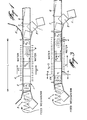
- Fig. 1 there is shown a first example of the present invention wherein there is illustrated a system of continuously extracting a liquid from a humid mass.
- Fig. 2 illustrates the liquid extraction mechanism which constitutes the principle on which the operation of the system of Fig. 1 is based.
- the system comprises a conduit A of rectangular cross-section which extends between the inlet I and the outlet 0 of the system.
- the conduit A has an active side wall 1 and a passive side wall 2.
- the active side wall is constituted by a plurality of panel sections each of which has a transverse panel 1' and opposed lateral panel 3', only one being shown in this Figure.
- the panel sections form a conduit of rectangular cross-section together with the opposed panel 2'.
- the conduit is formed in the straight section, between the inlet I and the outlet 0, by a plurality of these rigid panels 1', 2', and 3' which are constructed of thin rigid material having perforations 4 therein.
- the perforations are sufficient in number and size whereby to permit a liquid within the conduit to flow out of the conduit through the perforations.
- Each of the lateral panels 3' secured side by side at the opposed edges of the transverse panel 1' displaces itself along the conduit A on guide elements (not shown) but obvious in construction to a person skilled in the art.
- the panels 2' of the passive side wall 2 are also displaced in the same direction as the panels of the active side wall 1 but at a speed which is equal or less than that of the active side wall.
- the extraction conduit is fed a humid mass, by means of a feed mechanism 5 such as a spiral feed screw.
- a feed mechanism 5 such as a spiral feed screw.
- the feed is effected axially and produces by its pushing force an inlet pressure P and outlet pressure P on the humid mass which is conveyed along the conduit A.
- the pressure increases towards the exit 0 of the conduit A.
- the axial pressure P produces a differential pressure between the axial pressure applied in the central zone of the conduit and the weaker pressures created in the contact zone between the moving panels and the humid mass.
- This differential pressure causes liquid contained in the liquid mass to flow in a substantially transverse direction to the direction of displacement of the liquid mass. That is to say, the liquid in the humid mass is directed towards the periphery of the conduit A where a filtration or extraction of the liquid is effected through the perforations 4 provided in the various panels.
- the weak peripheral pressure is created by the friction force created between the liquid mass and the panels.
- the quantity of humid mass at the exit O, as well as the axial pressure could be controlled by a rigid gate 6 which is pivotally secured at the end of a collector channel 7 having the same cross-sectional dimension as that of the conduit A.
- the humid mass is displaced slowly from the inlet I to the outlet O at a speed which is different than the speed of displacement of the active and passive side walls whereby there is established between the inner surface of the panels and the humid mass dynamic friction forces which establish lateral pressures which are inferior to the pressure in the central zone of the conduit whereby to establish the differential pressure which causes the liquid to flow from the center of the humid mass towards the perforated side walls of the panels and also towards the back of the conduit whereby the liquid contained in the liquid mass is convected towards the exterior of the mass.
- the dynamic friction forces as well as the axial pressure increase from the inlet I to the outlet 0 of the conduit. This increase in the friction forces cause the humid mass to become more and more less humid as it is displaced towards the outlet of the conduit.
- the humid mass contains a large quantity of liquid and this liquid progressively diminishes as the humid mass is displaced along the conduit towards the outlet due to the continuous extraction of liquid toward the exterior at the conduit.
- the humid mass becomes more and more solid and the friction force and the pressure at its point of contact with the side walls of the conduit increases to achieve a maximum value at the outlet 0.
- the convection of the liquid towards the exterior of the conduit is enhanced by the design of the system wherein all along the conduit the humid mass compresses and causes deformation of the particles of fibers therein which again enhances the extraction of liquid.
- the system can be improved by conveying the panels 3' and 1' of the active side walls and the passive side walls at different speeds whereby to compress and mold the humid mass thereby enhancing the dewatering of the mass.
- the passive side wall 2 is displaced at a speed V2 which is lower than the speed V1 of the active side wall 1.
- the lateral pressure P' exerted on the contour of the conduit and the dynamic friction forces between the humid mass and the side walls generate friction forces F1 and F2.
- the friction coefficient f2 and f1 as well as the contact perimeters a2 and a1 (see the formula), being different, we obtain dynamic friction forces F1 superior to F2.
- the liquid extraction system is comprised substantially of the same elements as Fig. 1 but the filtrating panels constituting the side wall 2 have been replaced by a single stationary panel 2A.
- This panel 2A has perforations 4, as illustrated in Fig. 3A, which shows a cross-section of the conduit A along cross section lines A-A in Fig. 3. It is also seen in Fig. 3 that the cross-section of the conduit is constant from the inlet to the outlet which enhances the simplicity of the concept of the liquid extraction system of this invention.
- the mechanism for the extraction of liquid from the humid matter is similar to that as previously described with reference to Fig. 1 and produces substantially the same effects.
- the speed of the side wall 2A is nil, the differences in the speed between the active and passive side walls result in retarding the humid mass which is conveyed by the side walls and develops reciprocal friction forces but opposite and proportional to the lateral pressures exerted by the humid matter on the various side walls.
- the friction force F2 of the side wall 2A is smaller than the friction force F1 of the panel assembly of the active side wall due to the fact that the contact surface is larger between the moving panel assembly and the humid matter as well as the superior coefficient of friction between the panel assembly and the humid mass.
- the coefficient of friction of the side wall 2A can be lowered by coating the surface with a smooth material such as Teflon (registered trademark).
- the present system of continuously extracting liquid by pressurization of a humid mass offers important characteristics in comparison with other mechanical systems known in the art and namely, provides for an improved retention time of the humid mass in the interior of the conduit which results in an improved liquid extraction system.
- the retention time of the humid mass is related to various factors such as the output of the mass which is controlled by the control means 6 secured at the outlet of the conduit, the confined volume between the inlet and outlet of the conduit as well as the average density of the humid mass conveyed through the system.
- the present system of extraction by the use of differential pressure established between the friction force between the surfaces of contact and the humid matter provides for a retention time of the humid mass which is at least three times superior to that of the systems of the prior art resulting in a substantial increase of the utility of the present invention.
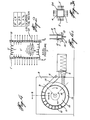
- Fig. 4 illustrates another example of the continuous liquid extraction system of the present invention from a humid mass and it constitutes a variant of the system of Fi g . 3.
- the system of Fig. 4 does not occupy as much space as that of Fi g . 3 due to the fact that the conduit 15 is disposed on a section of a circular arc instead of extending linearly but both systems have many common characteristics.
- the passive or external side wall is also maintained fixed and it is also constituted of a single member of which the interior surface is smooth to decrease the friction force in the contact area with the humid mass.
- the side wall 9 is maintained fixed by a rigid frame 8 which completely surrounds the system.
- Another common characteristic of this system resides in the fact that the cross-section of the channel or conduit 15 is also constant and rectangular.
- the driven (active) side wall 1 of the system of Fig. 3 is replaced by a wheel 10 which is also motor-driven and which is maintained at a substantially constant speed and it also acts in the same manner as the system of Fig. 3.
- This motorized wheel 10 is provided with an active side wall constituted by a peripheral flat wall 16 on which is secured lateral perforated side walls 12 maintained in position by reinforcing ribs see Fig. 4A).
- the peripheral wall 16 is also provided with perforations 13 through which liquid can flow.
- the amount of liquid in the humid mass is controlled by the control plane 6 which is hinged to the outlet collector channel 14 disposed at the outlet of the convection conduit.
- the supply of the humid mass is effected by any one of many conventional feed devices 5 wherein the output thereof can be controlled as a function of various parameters of the system, as previously discussed with reference to Fig. 3, and taking into consideration the desired retention time of the humid mass in the interior of the conduit 15.
- the friction force on the active side wall of the wheel remains much higher than the friction force on the internal surface of the outer panel 9 as the friction surface on the peripheral walls 16 and 12 is superior to that on the outer side wall 9.
- the coefficients of friction can be increased on the active side wall and decreased on the side wall 9 by appropriate means such as forming slots on the said active side wall or coating the internal surface of the wall 9 with a smooth material offering very little resistance, such as Teflon (registered trademark).
- Teflon registered trademark
- the liquid contained in the humid mass is drawn out by pressure towards the periphery of the wheel and through the perforations provided in the wall 16 of the wheel, the perforated side walls or panels 12 and the outer panel 9, such that the liquid in the humid mass is continuously diminished from the entrance I to the outlet O of the system.
- the pressures become more and more elevated towards the outlet of the conduit and the liquid in the mass continuously decreases.
- the angleo( shown in Fig. 4 is selected as being the proper angle determining the effective length or working section of the conduit 12 and variation of this angle will of course affect the maximum pressure that one can obtain at the outlet O of the system. The larger this angle, the higher the pressure at the outlet.
- the system above described possesses many advantages and particularities not found in prior art systems.
- the examples of the preferred embodiment described and illustrated provide in one of its aspects a constant rectangular cross-section from its inlet to its outlet which permits the passage of large foreign matter which may be agglomerated with the humid mass.
- the quantity of humid mass which is stored in the conduit and the retention time of the mass in the conduit is superior to the prior art, and at least three to five times superior. In other words, for a given retention time, the length of the conduit or the working section of the conduit will be at least three to five times shorter than an extraction conduit utilized in prior art.
- the control of the amount of liquid in the mass and of the maximum axial pressure exerted on the humid mass is achieved simply by increasing the resistance on the mass being convected at the outlet of the conduit and by simple mechanical means.
- the number of parts utilized in this system is substantially diminished as compared to the prior art which translates in a substantial reduction in weight of the apparatus forming this system.
- the cost of construction of the system and the cost of operation and maintenance is substantially reduced.
- the in- :ernal pressure increases gradually from the inlet to the outlet by moving the humid mass by means of a friction wheel and this being independent of the feed means.
- the pressure extraction system of the present invention envisages utilizing a conduit having cross-sections which are variable for either linear or arcuately disposed conduits.
- the active side wall may be of U or V shape cross-section or other suitable cross-section. It is also conceived that two or more of these systems can be used in parallel or in tandem to provide an economical operation or to provide a second stage of liquid extraction. It is also foreseen that the active and passive side walls may be constructed of tissues having suitable qualities to convect the liquid.
Landscapes
- Mechanical Engineering (AREA)
- Engineering & Computer Science (AREA)
- Extraction Or Liquid Replacement (AREA)
- Paper (AREA)
- Slide Fasteners, Snap Fasteners, And Hook Fasteners (AREA)
- Medicines Containing Plant Substances (AREA)
- Agricultural Chemicals And Associated Chemicals (AREA)
- Preliminary Treatment Of Fibers (AREA)
- Feeding, Discharge, Calcimining, Fusing, And Gas-Generation Devices (AREA)
- Organic Low-Molecular-Weight Compounds And Preparation Thereof (AREA)
- Processing And Handling Of Plastics And Other Materials For Molding In General (AREA)
- Clamps And Clips (AREA)
- Treatment Of Water By Ion Exchange (AREA)
Priority Applications (1)
| Application Number | Priority Date | Filing Date | Title |
|---|---|---|---|
| AT83401101T ATE34337T1 (de) | 1982-06-01 | 1983-05-31 | Verdichtungseinrichtung und verdichtungsverfahren zur gewinnung von fluessigkeit aus einer feuchten masse. |
Applications Claiming Priority (2)
| Application Number | Priority Date | Filing Date | Title |
|---|---|---|---|
| CA000404223A CA1193903A (fr) | 1982-06-01 | 1982-06-01 | Systeme et methode d'extraction d'un liquide par pressurage |
| CA404223 | 1982-06-01 |
Publications (3)
| Publication Number | Publication Date |
|---|---|
| EP0095985A2 true EP0095985A2 (de) | 1983-12-07 |
| EP0095985A3 EP0095985A3 (en) | 1985-05-22 |
| EP0095985B1 EP0095985B1 (de) | 1988-05-18 |
Family
ID=4122904
Family Applications (1)
| Application Number | Title | Priority Date | Filing Date |
|---|---|---|---|
| EP83401101A Expired EP0095985B1 (de) | 1982-06-01 | 1983-05-31 | Verdichtungseinrichtung und Verdichtungsverfahren zur Gewinnung von Flüssigkeit aus einer feuchten Masse |
Country Status (12)
| Country | Link |
|---|---|
| US (1) | US4534868A (de) |
| EP (1) | EP0095985B1 (de) |
| JP (1) | JPS5933099A (de) |
| AT (1) | ATE34337T1 (de) |
| AU (1) | AU558056B2 (de) |
| CA (1) | CA1193903A (de) |
| DE (1) | DE3376635D1 (de) |
| DK (1) | DK158035C (de) |
| FI (1) | FI78416C (de) |
| NO (1) | NO157372C (de) |
| PL (1) | PL139767B1 (de) |
| TR (1) | TR21896A (de) |
Cited By (3)
| Publication number | Priority date | Publication date | Assignee | Title |
|---|---|---|---|---|
| EP0406221A3 (en) * | 1989-06-28 | 1991-04-10 | Kamyr, Inc. | Liquid treatment of and liquid extraction on a paper pulp |
| FR2701664A1 (fr) * | 1993-02-19 | 1994-08-26 | Enitiaa | Procédé et installation de séparation des phases solides et liquides de matières organiques animales ou végétales. |
| CN103157316A (zh) * | 2013-03-29 | 2013-06-19 | 江苏涞森环保设备有限公司 | 一种旋转挤压式过滤机 |
Families Citing this family (9)
| Publication number | Priority date | Publication date | Assignee | Title |
|---|---|---|---|---|
| US5205941A (en) * | 1991-08-02 | 1993-04-27 | Kamyr, Inc. | Feeding equalization for sludge presses |
| US5213686A (en) * | 1991-08-26 | 1993-05-25 | Kamyr, Inc. | Compression feeder |
| US6004468A (en) * | 1998-07-17 | 1999-12-21 | Barbulescu; Adrian | Serial drum apparatus and method for processing wet material |
| CA2352414A1 (fr) | 2001-07-05 | 2003-01-05 | Industries Fournier Inc. | Dispositif de controle et de retenue des gateaux dans un pressoir rotatif |
| CN100493666C (zh) * | 2004-04-28 | 2009-06-03 | 巴工业株式会社 | 高脱水型旋转加压脱水机 |
| MX2007001426A (es) * | 2004-08-09 | 2008-03-11 | Prime Solution Inc | Prensa de ventilador giratorio. |
| US7975854B2 (en) * | 2005-10-28 | 2011-07-12 | Prime Solution, Inc. | Rotary fan press |
| US8662315B2 (en) * | 2008-07-14 | 2014-03-04 | Prime Solution, Inc. | Rotary fan press |
| MX378028B (es) | 2014-04-08 | 2025-03-10 | Prime Solution Inc | Prensa de ventilación rotatoria con barrena. |
Family Cites Families (12)
| Publication number | Priority date | Publication date | Assignee | Title |
|---|---|---|---|---|
| DE27601C (de) * | G. REMY in Beuchlitz bei Halle a. d. Saale | Schnitzelpresse mit endloser Rinne und Kette | ||
| BE369652A (de) * | ||||
| US483847A (en) * | 1892-10-04 | Ooqoqoxoooooooooooooooooo | ||
| DE185654C (de) * | ||||
| DE374811C (de) * | 1921-05-14 | 1923-04-30 | Georg Kaibel | Obstpresse |
| FR566456A (fr) * | 1922-08-24 | 1924-02-15 | Marmonier Fils | Pressoir continu à compression directe |
| US2409713A (en) * | 1942-08-19 | 1946-10-22 | Sharples Corp | Separation of liquids from solids |
| US2663427A (en) * | 1949-08-05 | 1953-12-22 | Brueckenbau Flender Gmbh | Installation for dewatering slimes |
| DE1298506B (de) * | 1967-01-18 | 1969-07-03 | Siemens Ag | Abscheider fuer Feststoffe aus Fluessigkeiten |
| US3550775A (en) * | 1968-03-29 | 1970-12-29 | William L Cooley | Method and means for separating entrained liquids from solids |
| DE2437510A1 (de) * | 1974-08-03 | 1976-02-12 | Draiswerke Gmbh | Verfahren zum flushen von in form von wasserhaltigen presskuchen vorliegenden pigmenten |
| GB1576819A (en) * | 1976-12-08 | 1980-10-15 | V H Pannevis & Zn Bv Maschf | Method and device for removing a liquid for a mixture of liquid and solid substances |
-
1982
- 1982-06-01 CA CA000404223A patent/CA1193903A/fr not_active Expired
-
1983
- 1983-05-12 US US06/493,811 patent/US4534868A/en not_active Expired - Lifetime
- 1983-05-25 FI FI831872A patent/FI78416C/fi not_active IP Right Cessation
- 1983-05-31 NO NO831953A patent/NO157372C/no unknown
- 1983-05-31 DE DE8383401101T patent/DE3376635D1/de not_active Expired
- 1983-05-31 EP EP83401101A patent/EP0095985B1/de not_active Expired
- 1983-05-31 AT AT83401101T patent/ATE34337T1/de not_active IP Right Cessation
- 1983-05-31 DK DK244583A patent/DK158035C/da not_active IP Right Cessation
- 1983-06-01 PL PL1983242307A patent/PL139767B1/pl unknown
- 1983-06-01 TR TR21896A patent/TR21896A/xx unknown
- 1983-06-01 JP JP58097761A patent/JPS5933099A/ja active Granted
-
1984
- 1984-03-20 AU AU25908/84A patent/AU558056B2/en not_active Ceased
Cited By (3)
| Publication number | Priority date | Publication date | Assignee | Title |
|---|---|---|---|---|
| EP0406221A3 (en) * | 1989-06-28 | 1991-04-10 | Kamyr, Inc. | Liquid treatment of and liquid extraction on a paper pulp |
| FR2701664A1 (fr) * | 1993-02-19 | 1994-08-26 | Enitiaa | Procédé et installation de séparation des phases solides et liquides de matières organiques animales ou végétales. |
| CN103157316A (zh) * | 2013-03-29 | 2013-06-19 | 江苏涞森环保设备有限公司 | 一种旋转挤压式过滤机 |
Also Published As
| Publication number | Publication date |
|---|---|
| US4534868A (en) | 1985-08-13 |
| DE3376635D1 (en) | 1988-06-23 |
| EP0095985B1 (de) | 1988-05-18 |
| FI78416B (fi) | 1989-04-28 |
| NO157372B (no) | 1987-11-30 |
| FI831872A0 (fi) | 1983-05-25 |
| DK158035C (da) | 1990-08-20 |
| TR21896A (tr) | 1985-10-10 |
| CA1193903A (fr) | 1985-09-24 |
| AU2590884A (en) | 1985-09-26 |
| AU558056B2 (en) | 1987-01-15 |
| FI831872L (fi) | 1983-12-02 |
| NO831953L (no) | 1983-12-02 |
| ATE34337T1 (de) | 1988-06-15 |
| DK158035B (da) | 1990-03-19 |
| PL139767B1 (en) | 1987-02-28 |
| DK244583D0 (da) | 1983-05-31 |
| DK244583A (da) | 1983-12-02 |
| JPS6325880B2 (de) | 1988-05-27 |
| NO157372C (no) | 1988-03-09 |
| EP0095985A3 (en) | 1985-05-22 |
| PL242307A1 (en) | 1984-03-12 |
| JPS5933099A (ja) | 1984-02-22 |
| FI78416C (fi) | 1989-08-10 |
Similar Documents
| Publication | Publication Date | Title |
|---|---|---|
| EP0095985B1 (de) | Verdichtungseinrichtung und Verdichtungsverfahren zur Gewinnung von Flüssigkeit aus einer feuchten Masse | |
| US4997578A (en) | Method and apparatus for dewatering and squeezing material | |
| EP0037041B1 (de) | Einrichtung zum kontinuierlichen Auspressen von Flüssigkeit aus einer Masse | |
| US4266473A (en) | Screw press with continuous slope feed screw | |
| US5743178A (en) | Screw press for dehydrating fibrous materials | |
| US5012731A (en) | Device for pressing heterogeneous mixtures with regulated pressing force for separating liquid and solid fractions thereof, in particular fruit juices | |
| JP2014151321A (ja) | 脱水機 | |
| US4397230A (en) | Screw press improvements | |
| US5337658A (en) | Conveying and compacting apparatus having a shaftless spiral in a casing with drainage openings | |
| US10118358B2 (en) | Screw press for separation of liquid from bulk materials | |
| US3624729A (en) | Continuous juice extractor | |
| EP0179842B1 (de) | Fördervorrichtung | |
| RU2351475C2 (ru) | Винтовой пресс для прессования волокнистого материала, в частности волокнистой массы сахарной свеклы | |
| JPS60255300A (ja) | スクリユ−プレス型汚泥脱水機 | |
| US3520411A (en) | Screenings press | |
| NZ207591A (en) | Extracting liquid from humid mass by forcing through perforated conduit whose sides move at relatively differing speeds | |
| WO1982003820A1 (en) | Screw press with continuous slope feed screw | |
| WO1983000306A1 (en) | Screw press for extracting liquids | |
| US3595162A (en) | Method for pressing liquid out of fibrous or woodlike material | |
| WO2003031166A1 (en) | A screw press and a method of pressing a liquid-containing substance as well as use thereof | |
| US2268753A (en) | Juice extractor | |
| US2293297A (en) | Squeezing device for plastic and semplastic masses | |
| EP0820859A2 (de) | Vorrichtung und Verfahren zum Verdichten von Werkstoffen | |
| JPS5946718B2 (ja) | スクリユ−プレス | |
| SU1761016A1 (ru) | Устройство дл обезвоживани навоза |
Legal Events
| Date | Code | Title | Description |
|---|---|---|---|
| PUAI | Public reference made under article 153(3) epc to a published international application that has entered the european phase |
Free format text: ORIGINAL CODE: 0009012 |
|
| AK | Designated contracting states |
Designated state(s): AT BE CH DE FR GB IT LI LU NL SE |
|
| PUAL | Search report despatched |
Free format text: ORIGINAL CODE: 0009013 |
|
| AK | Designated contracting states |
Designated state(s): AT BE CH DE FR GB IT LI LU NL SE |
|
| 17P | Request for examination filed |
Effective date: 19850711 |
|
| 17Q | First examination report despatched |
Effective date: 19860319 |
|
| D17Q | First examination report despatched (deleted) | ||
| GRAA | (expected) grant |
Free format text: ORIGINAL CODE: 0009210 |
|
| AK | Designated contracting states |
Kind code of ref document: B1 Designated state(s): AT BE CH DE FR GB IT LI LU NL SE |
|
| REF | Corresponds to: |
Ref document number: 34337 Country of ref document: AT Date of ref document: 19880615 Kind code of ref document: T |
|
| REF | Corresponds to: |
Ref document number: 3376635 Country of ref document: DE Date of ref document: 19880623 |
|
| ET | Fr: translation filed | ||
| ITF | It: translation for a ep patent filed | ||
| PLBE | No opposition filed within time limit |
Free format text: ORIGINAL CODE: 0009261 |
|
| STAA | Information on the status of an ep patent application or granted ep patent |
Free format text: STATUS: NO OPPOSITION FILED WITHIN TIME LIMIT |
|
| 26N | No opposition filed | ||
| ITTA | It: last paid annual fee | ||
| EPTA | Lu: last paid annual fee | ||
| EAL | Se: european patent in force in sweden |
Ref document number: 83401101.7 |
|
| PGFP | Annual fee paid to national office [announced via postgrant information from national office to epo] |
Ref country code: SE Payment date: 19980423 Year of fee payment: 16 |
|
| PGFP | Annual fee paid to national office [announced via postgrant information from national office to epo] |
Ref country code: LU Payment date: 19980508 Year of fee payment: 16 |
|
| PGFP | Annual fee paid to national office [announced via postgrant information from national office to epo] |
Ref country code: CH Payment date: 19980512 Year of fee payment: 16 |
|
| PGFP | Annual fee paid to national office [announced via postgrant information from national office to epo] |
Ref country code: AT Payment date: 19980518 Year of fee payment: 16 |
|
| PGFP | Annual fee paid to national office [announced via postgrant information from national office to epo] |
Ref country code: GB Payment date: 19990526 Year of fee payment: 17 |
|
| PGFP | Annual fee paid to national office [announced via postgrant information from national office to epo] |
Ref country code: FR Payment date: 19990528 Year of fee payment: 17 |
|
| PG25 | Lapsed in a contracting state [announced via postgrant information from national office to epo] |
Ref country code: SE Free format text: THE PATENT HAS BEEN ANNULLED BY A DECISION OF A NATIONAL AUTHORITY Effective date: 19990530 |
|
| PG25 | Lapsed in a contracting state [announced via postgrant information from national office to epo] |
Ref country code: LU Free format text: LAPSE BECAUSE OF NON-PAYMENT OF DUE FEES Effective date: 19990531 Ref country code: LI Free format text: LAPSE BECAUSE OF NON-PAYMENT OF DUE FEES Effective date: 19990531 Ref country code: CH Free format text: LAPSE BECAUSE OF NON-PAYMENT OF DUE FEES Effective date: 19990531 Ref country code: AT Free format text: LAPSE BECAUSE OF NON-PAYMENT OF DUE FEES Effective date: 19990531 |
|
| PGFP | Annual fee paid to national office [announced via postgrant information from national office to epo] |
Ref country code: NL Payment date: 19990531 Year of fee payment: 17 |
|
| PGFP | Annual fee paid to national office [announced via postgrant information from national office to epo] |
Ref country code: BE Payment date: 19990628 Year of fee payment: 17 |
|
| PGFP | Annual fee paid to national office [announced via postgrant information from national office to epo] |
Ref country code: DE Payment date: 19990728 Year of fee payment: 17 |
|
| REG | Reference to a national code |
Ref country code: CH Ref legal event code: PL |
|
| EUG | Se: european patent has lapsed |
Ref document number: 83401101.7 |
|
| PG25 | Lapsed in a contracting state [announced via postgrant information from national office to epo] |
Ref country code: GB Free format text: LAPSE BECAUSE OF NON-PAYMENT OF DUE FEES Effective date: 20000531 Ref country code: BE Free format text: LAPSE BECAUSE OF NON-PAYMENT OF DUE FEES Effective date: 20000531 |
|
| BERE | Be: lapsed |
Owner name: CENTRE DE RECHERCHE INDUSTRIELLE DU QUEBEC Effective date: 20000531 |
|
| PG25 | Lapsed in a contracting state [announced via postgrant information from national office to epo] |
Ref country code: NL Free format text: LAPSE BECAUSE OF NON-PAYMENT OF DUE FEES Effective date: 20001201 |
|
| GBPC | Gb: european patent ceased through non-payment of renewal fee |
Effective date: 20000531 |
|
| PG25 | Lapsed in a contracting state [announced via postgrant information from national office to epo] |
Ref country code: FR Free format text: LAPSE BECAUSE OF NON-PAYMENT OF DUE FEES Effective date: 20010131 |
|
| NLV4 | Nl: lapsed or anulled due to non-payment of the annual fee |
Effective date: 20001201 |
|
| PG25 | Lapsed in a contracting state [announced via postgrant information from national office to epo] |
Ref country code: DE Free format text: LAPSE BECAUSE OF NON-PAYMENT OF DUE FEES Effective date: 20010301 |
|
| REG | Reference to a national code |
Ref country code: FR Ref legal event code: ST |