EP0096048B1 - Suppresseur d'echo - Google Patents
Suppresseur d'echo Download PDFInfo
- Publication number
- EP0096048B1 EP0096048B1 EP82903466A EP82903466A EP0096048B1 EP 0096048 B1 EP0096048 B1 EP 0096048B1 EP 82903466 A EP82903466 A EP 82903466A EP 82903466 A EP82903466 A EP 82903466A EP 0096048 B1 EP0096048 B1 EP 0096048B1
- Authority
- EP
- European Patent Office
- Prior art keywords
- signal
- output
- path
- information
- sampling
- Prior art date
- Legal status (The legal status is an assumption and is not a legal conclusion. Google has not performed a legal analysis and makes no representation as to the accuracy of the status listed.)
- Expired
Links
- 238000005070 sampling Methods 0.000 claims description 63
- 230000005540 biological transmission Effects 0.000 claims description 31
- 230000003044 adaptive effect Effects 0.000 claims description 16
- 238000000605 extraction Methods 0.000 claims description 13
- 230000006870 function Effects 0.000 claims description 10
- 238000012544 monitoring process Methods 0.000 claims description 2
- 230000000979 retarding effect Effects 0.000 claims 1
- 230000004044 response Effects 0.000 abstract description 32
- 238000000034 method Methods 0.000 description 20
- 230000008859 change Effects 0.000 description 10
- 238000010586 diagram Methods 0.000 description 10
- 238000001514 detection method Methods 0.000 description 4
- 230000010354 integration Effects 0.000 description 4
- 238000012545 processing Methods 0.000 description 3
- 230000001360 synchronised effect Effects 0.000 description 3
- 230000001052 transient effect Effects 0.000 description 3
- 230000007704 transition Effects 0.000 description 3
- 238000012935 Averaging Methods 0.000 description 2
- 238000007792 addition Methods 0.000 description 2
- 238000004364 calculation method Methods 0.000 description 2
- 238000006243 chemical reaction Methods 0.000 description 2
- 230000001419 dependent effect Effects 0.000 description 2
- 238000001914 filtration Methods 0.000 description 2
- 230000008569 process Effects 0.000 description 2
- 238000004088 simulation Methods 0.000 description 2
- 230000009471 action Effects 0.000 description 1
- 230000006978 adaptation Effects 0.000 description 1
- 230000004075 alteration Effects 0.000 description 1
- 238000013459 approach Methods 0.000 description 1
- 229910002056 binary alloy Inorganic materials 0.000 description 1
- 238000004422 calculation algorithm Methods 0.000 description 1
- 238000004891 communication Methods 0.000 description 1
- 239000000470 constituent Substances 0.000 description 1
- 238000011437 continuous method Methods 0.000 description 1
- 239000013078 crystal Substances 0.000 description 1
- 238000013461 design Methods 0.000 description 1
- 230000000694 effects Effects 0.000 description 1
- 230000008030 elimination Effects 0.000 description 1
- 238000003379 elimination reaction Methods 0.000 description 1
- 230000006872 improvement Effects 0.000 description 1
- 230000007246 mechanism Effects 0.000 description 1
- 230000004048 modification Effects 0.000 description 1
- 238000012986 modification Methods 0.000 description 1
- 230000009467 reduction Effects 0.000 description 1
- 230000035945 sensitivity Effects 0.000 description 1
- 238000007493 shaping process Methods 0.000 description 1
- 238000001228 spectrum Methods 0.000 description 1
- 230000002459 sustained effect Effects 0.000 description 1
- 230000002123 temporal effect Effects 0.000 description 1
- 238000012546 transfer Methods 0.000 description 1
Images



Classifications
-
- H—ELECTRICITY
- H04—ELECTRIC COMMUNICATION TECHNIQUE
- H04L—TRANSMISSION OF DIGITAL INFORMATION, e.g. TELEGRAPHIC COMMUNICATION
- H04L25/00—Baseband systems
- H04L25/02—Details ; arrangements for supplying electrical power along data transmission lines
- H04L25/03—Shaping networks in transmitter or receiver, e.g. adaptive shaping networks
- H04L25/03006—Arrangements for removing intersymbol interference
- H04L25/03012—Arrangements for removing intersymbol interference operating in the time domain
- H04L25/03019—Arrangements for removing intersymbol interference operating in the time domain adaptive, i.e. capable of adjustment during data reception
- H04L25/03057—Arrangements for removing intersymbol interference operating in the time domain adaptive, i.e. capable of adjustment during data reception with a recursive structure
-
- H—ELECTRICITY
- H04—ELECTRIC COMMUNICATION TECHNIQUE
- H04B—TRANSMISSION
- H04B3/00—Line transmission systems
- H04B3/02—Details
- H04B3/20—Reducing echo effects or singing; Opening or closing transmitting path; Conditioning for transmission in one direction or the other
- H04B3/23—Reducing echo effects or singing; Opening or closing transmitting path; Conditioning for transmission in one direction or the other using a replica of transmitted signal in the time domain, e.g. echo cancellers
- H04B3/235—Reducing echo effects or singing; Opening or closing transmitting path; Conditioning for transmission in one direction or the other using a replica of transmitted signal in the time domain, e.g. echo cancellers combined with adaptive equaliser
Definitions
- This invention relates to a digital transmission system in which digital data information such as PCM is conveyed in either one of two directions over a single transmission path.
- the stations at the end of the transmission path each have a GO and RETURN path, these paths being coupled to the transmission path via a hybrid or its electronic equivalent.
- the transmission .path may be a two-wire twisted-pair which would normally be one of a number of such pairs in a cable.
- imperfections in the hybrid or its equivalent cause an unwanted signal to find its way from the GO to the RETURN path, and it is an object of this invention to provide for a substantially reduction in or elimination of this unwanted signal.
- the signals to be sent go via a line coder, which puts them, for instance, into a ternary code, after which a line driver converts the data into pulse forms, the pulsed data being applied to the line via a hybrid.
- the signal incoming from the hybrid is filtered to remove out-of-band noise, and then sampled at the baud rate in. an analogue-digital converter.
- the output of this converter includes the received signal, plus interference from the GO path.
- a controlled amplitude version of the GO path signal is subtracted from the RETURN path signal. This version is obtained via an adaptive filter whose input is from the line coder output and whose output goes to a subtractor whose other input is from the analogue-digital converter.
- the signal from the subtractor is distorted due to filterings and reflections which cause inter-symbol interference.
- the subtractor is followed by an adaptive decision feedback equaliser (ADFE), which is similar to the adaptive filter mentioned above.
- ADFE adaptive decision feedback equaliser
- the output from the ADFE is a applied to a line decoder, which does the inverse of the job done by the line coder.
- the output from the decoder is the desired signal, now expressed in binary form.
- the ADFE also provides the source for the clock extraction, which controls, inter alia, the sampling at the analogue-digital converter.
- the overall impulse response is such that a well-defined zero crossing occurs one baud interval after the ideal sampling instant.
- this estimate is used directly to control the phase adjustments in a loop configuration.
- the adaptive filter fed from the line coder uses a shift register via which the GO path signal passes, the stages having adjustable taps to a summator whose output is the version to be subtracted.
- the tap weights are adjusted automatically from the output of the subtractor.
- the error signal from the subtractor is multiplied by the contents of the appropriate register stage and the result added to an accumulator.
- a tap weight is incremented or decremented and the accumulator is reset.
- the dynamics of this loop are such as to give a reasonable compromise between accuracy and speed of adaptation by suitable choice of the threshold.
- the first tap is the adaptive threshold detector, detection being done by so selecting the ternary symbol for the first tap as to minimise the resulting error signal.
- An object of the present invention is to provide a system of the same general type as those envisaged by the authors of the above-quoted papers, but which is better in action than the system described in those papers.
- a digital transmission station for use in a system in which digital information is conveyed in either one of two directions over a single transmission path, wherein the station has GO and RETURN paths coupled to the transmission path via a hybrid or its equivalent, wherein the GO path includes an encoder which encodes the information to be conveyed into a format suitable for conveyance over said single path prior to its application to the hybrid or its equivalent, wherein in the RETURN path the received information is applied to an analogue-to-digital converter which produces from the information as received via the hybrid or its equivalent one output per received information symbol, which output has a digital format and represents the signal value at a specific sampling instant, wherein the output from the converter is applied to one input of a subtraction circuit, the information thus applied including an unwanted signal due to the imperfections of the hybrid or its equivalent, wherein the output of the encoder in the GO Path is applied via an echo simulator to another input of the subtraction circuit in the RETURN path such that said other input receives a version of the signal
- this arrangement involves the use of digital signal processing techniques to achieve full duplex transmission of digital information, in the present case PCM, on a single pair of a multiple twisted-pair cable, in particular 144 kbt/s on exchange to subscriber loops.
- PCM digital signal processing techniques
- the processing operations are performed at the line symbol rate and to minimise both near-end and far-end cross-talk, and also noise sensitivity, the non-linear process of decision feedback equalisation (DFE) is used.
- DFE decision feedback equalisation
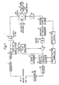
- FIG. 1 is a digital transmission station embodying the invention.
- a system using the present invention there are two ends, the master end being the one with a master oscillator which controls the PCM transmission rate, the other or slave end being synchronised to the master end by a clock synchronisation circuit.
- the two ends differ because of the clock extraction and sampling time adjustment needs, but the system operates at each end substantially as will be described with reference to Fig. 1, which shows schematically the component parts of one end of the echo cancelling transmission system.
- the binary data to be transmitted in the GO path is initially scrambled by a scrambler 1 to eliminate auto-correlation in the transmitted data and correlation between in the two directions of transmission.
- the encoder 2 to which the output of the scrambler 1 is applied is a differential encoder. This gives a binary output at the same rate as the input, such that the output changes when the input is 1 and does not change when the input is 0.
- the encoded information is applied to a transmit filter 3 to reduce high frequency energy sent to the cable at frequencies greater than half the symbol rate. This filter can be a first order low pass filter with 3dB attenuation at the system's bit rate.
- the line hybrid 4 couples the output from the filter 3, which is the transmit signal, to the line, and presents a resistive impedance to the line of 140 ohms..
- a filter 7 which precedes an analogue-to-digital converter 8, which filter limits the spectrum of the received data to be half bit rate. It can be a third order Butterworth filter with attenuation of -6dB at the half digit rate.
- the converter converts the signal from the line into a form more suitable for processing in the rest of the RETURN path.
- the received signal comprises the wanted far end signal, plus unwanted local signal due to the imperfect loss of the hybrid 4.
- the impulse response from the GO path to the echo canceller subtractor 9 is referred to as the trans-hybrid impulse response.
- the output of the converter 8 is applied to a digital filter 10 whose parameters depend on the way timing extraction is implemented, but in a simple case the filter 10 has the response 1-Z-'.
- the GO and RETURN paths are coupled by a sample and hold circuit 11 and a digital adaptive echo simulator 12.
- This simulator is an adaptive transversal filter which adjusts automatically to match the transhybrid impulse response until the difference signal from the subtractor 9 has substantially no local signal content. It generates one output for each sampled input value from the sample and hold circuit 13.
- the simulator 12 operates on the data to be sent, which is gated into it according to the method of timing extraction. Note the output from the subtractor 9 to the simulator 12.
- the output from the subtractor 9 is also applied to an adaptive decision feedback equaliser (ADFE) 14, whose purpose is to detect the received symbol values and to remove inter-symbol interference (ISI) between received symbols due to the transmission through the cable.
- the equaliser also controls the timing due to its constant estimation of the channel impulse response, see below.
- This ADFE can be similar in principle to that of our British Patent Application No. 2086193A, published May 6th, 1982.
- the output of this ADFE is applied to a timing extraction controller 15, which via a sampling time control circuit 16 controls the sample and hold circuit 13.
- the output of the ADFE 14 is also'applied to a decoder 17, in effect the inverse of the encoder 2, whose output passes to a descrambler 18 whose output is the RETURN signal output. Also associated with the decoder 17 is an error estimation circuit 19.
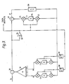
- Fig. 2 shows the echo canceller, which includes the echo simulator (12, Fig. 1), which is fed by the sample and hold circuit 11 and which feeds the subtractor 9 at which echo cancellation takes place.
- the hybrid output consists of a convolution of the transmitted symbols with the TIR, plus the far-end transmission F i and an external noise component N i
- the echo simulator (12, Fig. 1) is an adaptive transversal filter having (m+1) coefficients, and consists of m symbol delay elements such as 21, 22, and (m+1) accumulators formed by the elements 23, 24, 25 which store the coefficient values, with two multipliers such as ma(1) and mu(1) per coefficient.
- the current transmitted symbol value T i and the previous m transmitted symbol values are multiplied by the accumulator values K, using the multipliers mu(1 ) to mu(m) to form an estimate of the transhybrid signal component of the signal Z,.
- the difference signal between the sampled input signal R i and the echo simulator estimate Z i is S I :
- the difference signal derived from the output of the subtractor 9, is scaled by a factor 1/C, in an error scaler 27, and used to increment each accumulator after correlations with the corresponding symbol value using multipliers ma(1) to ma(m).
- the new coefficient value K n is then
- the system is based on an ADFE, Fig. 3 operating on the echo cancelled output which is samples spaced by one symbol period.
- the function of the ADFE is to remove ISI at the decision point by subtraction just before the decision point.
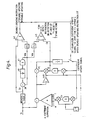
- Fig. 3 represents the operation of the ADFE.
- the impulse responses (TIR) must have a rise time to maximum or near maximum value at most equal to the time between successive transmitted symbols.
- the first clearly-defined maximum of the impulse response for a given set of symbol spaced samples is called the cursor value of the response.
- the channel is assumed to be linear in that the superposition principle applies throughout from transmitter to receiver. Note that the sequence-dependent equalisation may be used to overcome certain types of nonlinearity. It is also assumed that after a finite time, the summation of all unsigned values of the impulse response is finite and less than the cursor value, such that a finite length equaliser may be used.
- the sampled input signal S has subtracted from it by a subtractor 30 an estimate of the ISI at that sample time formed by summating the ISI due to.previous symbols.
- the nth constituent of the sum, produced by the summator 31 is formed by the product of the nth previous decision value, and the nth post cursor unit symbol time response estimate.
- the decision value from the current sample is D, that for the nth previous sample is D i-n , and the estimated value of the unit symbol time response at time t due to a symbol received at t i-n is C n .
- This estimate is the coefficient value, so the estimate of ISI due to each previously received symbol at t i-n is D i-n C n .
- the sampled value free of estimated post cursor ISI is passed to the threshold detector 32, which determines the symbol value. The value on which the decision due to the sample S, is made is thus
- the decision value (D ; ) is then multiplied using element 35 by a cursor coefficient estimate C o , which is the value of the accumulator element 34.
- This product is then subtracted by a subtractor 37 from the value at the input of the detector 32, and is termed the error value.
- the error value is formed by the following calculation:
- the error estimate is used to update the coefficient values C o to C n .
- Each coefficient is then incremented by the product of the error value scaled by element 36 and the symbol value used to form the product with that coefficient in deriving the error value.
- the new value of the nth coefficient C) becomes.
- Fig. 4 shows additions to the ADFE for disabling the coefficient values when a large transient is detected at the input, and for detecting the state which can occur when the equaliser is in a stable but invalid operating state.
- a weighted running mean W m is produced by the subtractor 30, scaling circuit 40 and accumulator 41.
- the coefficient updating is disabled for F3 symbols, via a threshold detector 42 if the ratio of the magnitude of the input sample value to the mean value S i /W m exceeds F1.
- the weighted running mean W m is also used to detect lock-up by comparison in a threshold device 43 with the value of the ADFE cursor value C o , which is always positive. If the ratio of Co/Wm>F2, the coefficients are set to zero as can be seen in Fig. 4.
- the slave end extraction is controlled by defining specific ratios between symbol spaced values of the overall transmission impulse response between the transmitter and receiver.
- the sampling time is adjusted until these conditions are met.
- the required correlation ratios may be varied according to other criteria to maintain an optimum sampling instant under differing conditions.
- the absolute value of the weighted running mean W m is used for this purpose.
- the system diagram of Fig. 6 defines the operations needed to derive a signal to control a phase locked loop directly from the coefficients.
- Fig. 6 relates to the ADFE with means to produce an estimate of a control signal generated for timing extraction control.
- the time constants for control of the sampling control loop may be chosen separately from the integration constants of the equaliser proper.
- the function of the system of Fig. 6 is to produce the value ⁇ h(0)+ ⁇ h(1) and the signal is then used to control a phase-locked loop or a switched phase adjustment, as described below.
- the basic structure and operation of the ADFE is as described above, see Fig. 3.
- the two values needed in this case are referred to as independent estimates of the cursor value and the first post- cursor value.
- Each is formed as follows.
- the error signal e i which comes from the subtractor 37 is the remainder of the sampled input signal after the cursor and all post-cursor estimates of the sequence of transmitted symbols convolved with the transmission channel have been removed.
- An estimate of the value of the cursor coefficient C o is formed by the loop consisting of the symbol value and coefficient accumulator multiplier 35, the subtraction of the cursor content of the signal by the subtractor 37, the scaling function 36, and the correlation formed by the multiplier and accumulator 33, 34.
- the loop integration time is controlled by the value of ⁇ which is the loop gain.
- the value D i times C o is added back into the error signal e, and the product of this modified remainder with the appropriate decision value is used for timing control.
- Independent estimates of any postcursor value may similarly be obtained. These may then be scaled and added or subtracted to give the control signal.
- the coefficients themselves may be directly used if the inherent integration time constant defined by A are suitable.
- a particular feature of this operation is that it introduces no discontinuity in correct operation of the system.
- a weighted sum of the channel estimates M(0) to M(n) is formed which is to be zero-forced.
- the use of a signal (X) to control the coefficients of the weighted sum either continuously or in steps enables the system to be adapted to suit different channel characteristics.
- W m and C o are indicators of the magnitude of the signal which for a cable may be used to adjust to a predictable sampling time optimum.
- the loop gain of the phase-locked loop may also be adjusted to compensate for a reduced input signal amplitude.
- the lossy integrator 72, 73, 74, with integration scaling constant y, provides a steady control voltage for the VCO 75 after the digital to analogue conversion.
- the coefficient estimates available from the accumulator outputs are used directly.
- the function is performed digitally and the sign of the result used directly to control the VCO such that if the sign is +ve then the VCO is set to its maximum frequency, while if the sign is -ve the VCO is set to its minimum frequency.
- the VCO range must be limited. The system operates satisfactorily with an oscillator range of up to ⁇ 1000 parts per million.
- the modified channel estimates M(n) as defined above are used.
- the predetermined function is performed digitally and the sign of the result is used to interface to analogue circuitry.
- An analogue integrator then precedes the VCO, the time constants of the integrator and VCO being chosen to match the system requirements.
- a fourth implementation of the slave end timing control uses a digital phase locked loop, and the circuit is similarto that to be described for the master end timing extraction. The difference is that the canceller sample and hold, the receiver sample and hold and the transmitter symbol clock are all operated in synchronism and the phase of all three are simultaneously advanced or retarded in small steps with respect to a fixed crystal oscillator reference clock nominally of frequency equal to the master clock at the master end.
- the following description may thus be applied to the slave end by considering these three synchronous clocks to be controlled from the receiver sampling clock. Further by virtue of the echo canceller being in synchronism with the receiver sampling clock, transferable echo canceller coefficients are not required, and the waiting period between phase steps can be shortened.
- the master end of the system is the end with the reference clock, which for an exchange to subscriber loop is the exchange end.
- the control signals used may be derived as described above. Only the sign of the resultant signal is important, as the adjustment is a single step forwards or backwards in time with respect to the nominal symbol interval. Referring to Fig. 8 at the master end the transmitter clock is locked to the local clock reference and the sample instruction is adjusted in small steps, there being S steps in a symbol period.
- a "fold-around” technique is used in the controlling circuitry. At the master end this involves an alteration to the echo canceller so that at the "fold-around" boundary there is no discontinuity of operation. Operation of the timing may be explained with reference to Figs. 8 and 9.
- the sampling time is adjusted with respect to a reference point, which is the local reference clock figure 8(a).
- the sampling time can only change by one step at a time, and two methods which limit the frequency with which steps can occur and which allow the canceller coefficients to adapt to the new sampling time and consequent change in the sampled trans-hybrid symbol impulse response are described.
- the step size is a fraction of a symbol period so that the change in the trans-hybrid impulse response is limited and does not cause an error.
- the symbol transmit clock is split into S steps such that the receiver sample and hold clock is adjustable to any position between 0 and S-1 by the control circuitry.
- the receiver sampling time is controlled from a register which defines the current position of the sampling time in terms of the number of steps from the transmit symbol clock; this phase register value corresponds to the receiver sampling phase.
- Sampling phase 0 corresponds to no time difference between the local clock reference and the receiver sampling clock.
- the local clock reference is defined in Fig. 8(a), and all other clocks are referred to this reference.
- the phase register values are defined in Fig. 8(d).
- the 0 to 1 transition of the clock is taken to be the edge upon which data is moved into and out of the clocked device.
- the sampling phase controlling register content is reduced by one. If the sampling phase is at position 0, the register value and corresponding sampling phase is changed to value S-1.
- the timing diagram for the change is given in Fig. 8(f) and it is important to note that two receiver samples occur during the transmission cycle 2.
- the first method of limiting the step frequency is to latch the phase register every pth symbol, depending on the sign of the control signal.
- the control signal is fed to an up/down counter which is incremented or decremented during each symbol period.
- the up/down counter reaches its limit L and is further incremented, it is reset to zero and increments the phase register.
- the up/down counter is at value zero and is further decremented, the phase register is then decremented, and the up/down counter is set to value L.
- the echo canceller sample and hold clock is also controlled by the sampling phase circuitry.
- the echo simulating filter is an adaptive transversal filter operating on the transmitted data, its output, is synchronous with the receiver sample and hold clock.
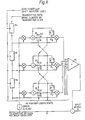
- Figs. 8(f) and 8(g) it may be seen that there is a slip between the transmitted data and the receiver sample time such that if the receiver sample and hold clock is used to clock data into the echo canceller, a discontinuity of operation would occur when the sampling phase changes from 0 to S-1 and vice-versa. This is overcome by altering the echo simulator as shown in Fig. 9.
- the simulation filter is altered in two ways. Firstly the accumulators are linked so that the coefficient values may be shifted forward or backward. Secondly, the clocking of the transmitted data into the symbol shift register prior to multiplication by the accumulator values may be altered to allow for the receiver timing phase changes across the 0 to S-1 boundary and vice-versa.
- the sequence of operation for an advance in sampling time corresponding to a change in the sampling phase register value from 0 to S-1 is as follows.
- the symbol shift register is not clocked.
- the multiplexers 90, 91, 92 steering the coefficient values are set to the advance state "A" so that the coefficient value operated on by the input data is shifted back one position through the adaptive filter.
- the sum of products is formed in the usual way as explained above, using the summator 93 and the algorithm presented.
- the multiplexers are returned to the normal state ("N") and operation continues as above. The net result of this cycle has been to transfer the coefficients back through the adaptive filter by one position.
- the sequence of operation for a retard transition in sampling time from a sampling phase S-1 to a sampling phase 0 is as follows.
- the symbol shift register 94-95-96 is clocked twice.
- the first symbol register clock pulse is timed to coincide with sampling pulse 0 immediately following the transmit clock which is specifically not used to clock the receiver sample and hold as previously mentioned. This is shown dotted in Fig. 8(g).
- the second shift register pulse is generated at the same time as the receiver sampling time.
- a preferred implementation of the digital phase locked loop in particular where the number of steps (S) and the capacity (L) of the prescaling up/down counter are integral powers of 2, is to use .
- an up/down counter of length log 2 (L+S) Ls+1 as a combined phase register and prescaler.
- Log 2 (x) is defined as the logarithm to the base 2 of x.
- the S most significant bits of the up/down counter thus represent the phase register value and the remaining least significant bits form the prescaling accumulator.
- the up/down counter is incremented or decremented depending on the sign of the timing control signal derived directly from the coefficient values using the preferred ratios described above.
- a suitable value for the number of steps S at both slave and master ends is 128.
- LRC local reference clock
- the down counter On reaching zero the down counter outputs a pulse which is used as the receiver sample clock. This pulse is also used to automatically reset the down counter to the value stored in the phase register.
- the system is designed so that it will ignore any commence count instruction from the LRC which occurs less than two S clock intervals after the down counter reaches zero.
- the preferred code encodes 3 binary digits as two ternary digits (3B2T).
- the code word table is define below.
- the ternary code word 11 is not used, which enables code word synchronisation by recognition of the word violation 11.
- the ternary frame size is 12 symbols.
- a method of frame synchronisation is used for which at every 8th ternary frame, the ternary word 1111 is added, which enables frame synchronisation.
- a second implementation is the addition of the 111 ternary code word every sixth ternary frame. The increase in ternary symbol rate in both cases is 100/96.
- a preferred method of transmission is to use transmission potentials of -V,0 and +V volts, corresponding to the ternary symbol values 0,1 and 2 respectively. Operation of the echo canceller is exactly as previously described the symbol registers however containing three level symbol values -1,0 and +1. The decision feedback equaliser operation is similarly altered. In addition a three level detection process is employed in which the comparator function defined in Fig. 3 is expanded to cater for the ternary transmission code as follows:
- the first method is only applicable to the ternary system or a similarly coded system, the important property of which is the use of a restricted set of code words in which the occurrence of certain code words may be seen to be a code violation.
- the code word 11 is used for word synchronisation.
- the occurrence of the code word 11 except as part of the frame synchronisation word 1111 may be interpreted as an error indicator, and the frequency of this violation used as a measure of error rate.
- the confidence limit to which an error rate may be measured using this approach depends on the ratio of word violations to the permitted symbol sequence 11 which may straddle two code words and is used for word synchronisation. As this limit is approached the word synchronisation may at a particular threshold be considered lost, and thus operate an alarm if not regained.
- the inability to define word synchronisation as described above may also be used to reset the coefficients of the echo canceller and the equaliser adaptive filters to zero, interpreting the word synchronisation loss as the result of system lock - up.
- the second method of error detection uses the estimation of the eye height given by the coefficient C o and the error estimate e defined in the equaliser description in the preceding text, both of which are available and updated for each symbol received.
- the difference signal between the magnitude of C o and the magnitude of a scaled value of the error signal may be used as an indicator of the error rate of the system.
- An alternative measure of system performance may be obtained by calculating the running mean of the difference in magnitudes between the cursor coefficient value and the error signal e, which gives an absolute measure of the mean margin against noise.
Landscapes
- Engineering & Computer Science (AREA)
- Computer Networks & Wireless Communication (AREA)
- Signal Processing (AREA)
- Power Engineering (AREA)
- Cable Transmission Systems, Equalization Of Radio And Reduction Of Echo (AREA)
- Filters That Use Time-Delay Elements (AREA)
- Interface Circuits In Exchanges (AREA)
- Networks Using Active Elements (AREA)
Claims (5)
Priority Applications (1)
| Application Number | Priority Date | Filing Date | Title |
|---|---|---|---|
| AT82903466T ATE21308T1 (de) | 1981-11-19 | 1982-11-18 | Echokompensator. |
Applications Claiming Priority (2)
| Application Number | Priority Date | Filing Date | Title |
|---|---|---|---|
| GB8134898 | 1981-11-19 | ||
| GB08134898A GB2111354B (en) | 1981-11-19 | 1981-11-19 | Echo canceller |
Publications (2)
| Publication Number | Publication Date |
|---|---|
| EP0096048A1 EP0096048A1 (fr) | 1983-12-21 |
| EP0096048B1 true EP0096048B1 (fr) | 1986-08-06 |
Family
ID=10526000
Family Applications (1)
| Application Number | Title | Priority Date | Filing Date |
|---|---|---|---|
| EP82903466A Expired EP0096048B1 (fr) | 1981-11-19 | 1982-11-18 | Suppresseur d'echo |
Country Status (12)
| Country | Link |
|---|---|
| US (1) | US4539675A (fr) |
| EP (1) | EP0096048B1 (fr) |
| BE (1) | BE895066R (fr) |
| CA (1) | CA1210471A (fr) |
| DE (2) | DE3272474D1 (fr) |
| ES (1) | ES517479A0 (fr) |
| FI (1) | FI74560C (fr) |
| GB (1) | GB2111354B (fr) |
| NL (1) | NL8204483A (fr) |
| NO (1) | NO161098C (fr) |
| SE (1) | SE8206608D0 (fr) |
| WO (1) | WO1983001876A1 (fr) |
Families Citing this family (42)
| Publication number | Priority date | Publication date | Assignee | Title |
|---|---|---|---|---|
| DE3327467A1 (de) * | 1983-07-29 | 1985-02-14 | Siemens AG, 1000 Berlin und 8000 München | Verfahren und schaltungsanordnung zur kompensation von echosignalen |
| EP0139814A3 (fr) * | 1983-09-30 | 1986-07-30 | Siemens-Albis Aktiengesellschaft | Circuit égalisateur actif |
| IT1178913B (it) * | 1984-03-26 | 1987-09-16 | Cselt Centro Studi Lab Telecom | Sistema per la trassmissione bidire zionale con cancellazione d eco |
| DE3583052D1 (de) * | 1984-03-30 | 1991-07-11 | Siemens Ag | Schaltungsanordnung zum pruefen der funktionsfaehigkeit einer datenuebertragunseinrichtung. |
| EP0167677B1 (fr) * | 1984-07-13 | 1989-03-08 | BELL TELEPHONE MANUFACTURING COMPANY Naamloze Vennootschap | Dispositif de traitement de signaux |
| US4650930A (en) * | 1985-02-13 | 1987-03-17 | Northern Telecom Limited | Adaptive equalizer |
| SE447777B (sv) * | 1985-04-22 | 1986-12-08 | Ellemtel Utvecklings Ab | Forfarande for instellning av ett digitalt utjemnarfilter vid samtidig adaptiv ekoeliminering och adaptiv eliminering av storningar som uppstar genom intersymbolinterferens, samt anordning for genomforande av forfarande |
| GB2182826B (en) | 1985-11-20 | 1990-08-01 | Stc Plc | Data transmission system |
| GB2183971B (en) * | 1985-12-05 | 1989-10-04 | Stc Plc | Data transmission system |
| EP0239293A3 (fr) * | 1986-03-24 | 1988-12-14 | Gpt Limited | Systèmes de transmission de données |
| US4809203A (en) * | 1986-08-25 | 1989-02-28 | Ford Aerospace & Communications Corporation | Hybrid analog-digital filter |
| NL8603247A (nl) * | 1986-12-22 | 1988-07-18 | At & T & Philips Telecomm | Adaptief tijd-discreet filter voor het vormen van een compensatiesignaal uit synchrone datasymbolen. |
| FR2614484B1 (fr) * | 1986-12-30 | 1994-04-08 | Telecommunications Sa | Terminal de transmission de donnees sur une voie analogique bidirectionnelle avec annulation d'echo couplee au rythme reception |
| US4989221A (en) * | 1987-03-30 | 1991-01-29 | Codex Corporation | Sample rate converter |
| US4982428A (en) * | 1988-12-29 | 1991-01-01 | At&T Bell Laboratories | Arrangement for canceling interference in transmission systems |
| US5125024A (en) * | 1990-03-28 | 1992-06-23 | At&T Bell Laboratories | Voice response unit |
| US5263019A (en) * | 1991-01-04 | 1993-11-16 | Picturetel Corporation | Method and apparatus for estimating the level of acoustic feedback between a loudspeaker and microphone |
| FR2710211A1 (fr) * | 1993-09-13 | 1995-03-24 | Trt Telecom Radio Electr | Dispositif de détection de rupture de ligne et modem comportant un tel dispositif. |
| US5471527A (en) | 1993-12-02 | 1995-11-28 | Dsc Communications Corporation | Voice enhancement system and method |
| US5627885A (en) * | 1994-02-14 | 1997-05-06 | Brooktree Corporation | System for, and method of, transmitting and receiving through telephone lines signals representing data |
| US5887059A (en) * | 1996-01-30 | 1999-03-23 | Advanced Micro Devices, Inc. | System and method for performing echo cancellation in a communications network employing a mixed mode LMS adaptive balance filter |
| US5889827A (en) * | 1996-12-12 | 1999-03-30 | Ericsson Inc. | Method and apparatus for digital symbol detection using medium response estimates |
| US6597732B1 (en) * | 1999-01-14 | 2003-07-22 | Eric Morgan Dowling | High-speed modem with uplink remote-echo canceller |
| US6341360B1 (en) * | 1999-03-08 | 2002-01-22 | International Business Machines Corporation | Decision feedback equalizers, methods, and computer program products for detecting severe error events and preserving equalizer filter characteristics in response thereto |
| US6553518B1 (en) | 1999-03-08 | 2003-04-22 | International Business Machines Corporation | Severe error detectors, methods and computer program products that use constellation specific error event thresholds to detect severe error events during demodulation of a signal comprising symbols from a plurality of symbol constellations |
| US7003030B2 (en) | 1999-03-08 | 2006-02-21 | Lenovo (Singapore) Pte. Ltd. | Receivers, methods, and computer program products for an analog modem that receives data signals from a digital modem |
| US6381267B1 (en) | 1999-03-08 | 2002-04-30 | International Business Machines Corporation | Modems, methods, and computer program products for falling back to a lower data rate protocol upon detecting abnormal line conditions during startup |
| US6389064B1 (en) * | 1999-03-08 | 2002-05-14 | International Business Machines Corporation | Modems, methods, and computer program products for identifying a signaling alphabet in variance with an ideal alphabet due to digital impairments |
| US6661837B1 (en) | 1999-03-08 | 2003-12-09 | International Business Machines Corporation | Modems, methods, and computer program products for selecting an optimum data rate using error signals representing the difference between the output of an equalizer and the output of a slicer or detector |
| US6487243B1 (en) | 1999-03-08 | 2002-11-26 | International Business Machines Corporation | Modems, methods, and computer program products for recovering from errors in a tone reversal sequence between two modems |
| US6816100B1 (en) | 1999-03-12 | 2004-11-09 | The Regents Of The University Of California | Analog-to-digital converters with common-mode rejection dynamic element matching, including as used in delta-sigma modulators |
| US6661847B1 (en) | 1999-05-20 | 2003-12-09 | International Business Machines Corporation | Systems methods and computer program products for generating and optimizing signal constellations |
| GB2362063A (en) * | 2000-04-25 | 2001-11-07 | Mitel Corp | Connecting broadband voice and data signals to telephone systems |
| US7239680B2 (en) * | 2002-07-17 | 2007-07-03 | Broadcom Corporation | Methods for performing channel diagnostics |
| US7480326B2 (en) * | 2002-07-17 | 2009-01-20 | Broadcom Corporation | Channel diagnostic systems and methods |
| US7251213B2 (en) * | 2002-09-17 | 2007-07-31 | At&T Corp. | Method for remote measurement of echo path delay |
| US7440499B2 (en) * | 2004-01-29 | 2008-10-21 | Infineon Technologies Ag | Fractional spaced equalizer |
| DE102004025576B4 (de) * | 2004-05-25 | 2006-03-30 | Infineon Technologies Ag | Sende-und Empfangsanordnung mit einer Regelung zur Störsignalunterdrückung |
| EP1796281B1 (fr) * | 2005-12-09 | 2015-08-12 | Mitel Networks Corporation | Annuleur d'écho |
| JP4771532B2 (ja) * | 2006-02-01 | 2011-09-14 | オンセミコンダクター・トレーディング・リミテッド | エコー防止回路及びデジタル信号処理回路 |
| US8331430B2 (en) * | 2006-08-02 | 2012-12-11 | Broadcom Corporation | Channel diagnostic systems and methods |
| CN103557753B (zh) * | 2013-10-24 | 2015-05-27 | 北京理工大学 | 一种激光回波模拟装置及方法 |
Family Cites Families (2)
| Publication number | Priority date | Publication date | Assignee | Title |
|---|---|---|---|---|
| NL170688C (nl) * | 1976-06-28 | 1982-12-01 | Philips Nv | Inrichting voor simultane tweerichtingsdatatransmissie over tweedraadsverbindingen. |
| JPS5617532A (en) * | 1979-07-20 | 1981-02-19 | Nec Corp | Automatic equalizer |
-
1981
- 1981-11-19 GB GB08134898A patent/GB2111354B/en not_active Expired
-
1982
- 1982-11-18 US US06/522,378 patent/US4539675A/en not_active Expired - Lifetime
- 1982-11-18 DE DE8282903466T patent/DE3272474D1/de not_active Expired
- 1982-11-18 FI FI823967A patent/FI74560C/fi not_active IP Right Cessation
- 1982-11-18 DE DE19823242577 patent/DE3242577A1/de not_active Withdrawn
- 1982-11-18 EP EP82903466A patent/EP0096048B1/fr not_active Expired
- 1982-11-18 WO PCT/GB1982/000329 patent/WO1983001876A1/fr not_active Ceased
- 1982-11-18 ES ES517479A patent/ES517479A0/es active Granted
- 1982-11-18 NO NO823856A patent/NO161098C/no unknown
- 1982-11-19 CA CA000415944A patent/CA1210471A/fr not_active Expired
- 1982-11-19 BE BE2/59916A patent/BE895066R/fr active
- 1982-11-19 SE SE8206608A patent/SE8206608D0/xx unknown
- 1982-11-19 NL NL8204483A patent/NL8204483A/nl not_active Application Discontinuation
Also Published As
| Publication number | Publication date |
|---|---|
| GB2111354B (en) | 1985-06-19 |
| FI74560C (fi) | 1988-02-08 |
| FI823967A0 (fi) | 1982-11-18 |
| DE3242577A1 (de) | 1983-05-26 |
| NL8204483A (nl) | 1983-06-16 |
| CA1210471A (fr) | 1986-08-26 |
| SE8206608D0 (sv) | 1982-11-19 |
| EP0096048A1 (fr) | 1983-12-21 |
| DE3272474D1 (en) | 1986-09-11 |
| NO161098B (no) | 1989-03-20 |
| GB2111354A (en) | 1983-06-29 |
| WO1983001876A1 (fr) | 1983-05-26 |
| BE895066R (fr) | 1983-05-19 |
| ES8402128A1 (es) | 1984-01-16 |
| FI74560B (fi) | 1987-10-30 |
| NO161098C (no) | 1989-06-28 |
| ES517479A0 (es) | 1984-01-16 |
| FI823967L (fi) | 1983-05-20 |
| US4539675A (en) | 1985-09-03 |
| NO823856L (no) | 1983-05-20 |
Similar Documents
| Publication | Publication Date | Title |
|---|---|---|
| EP0096048B1 (fr) | Suppresseur d'echo | |
| US4878232A (en) | Data transmission system | |
| US4766589A (en) | Data transmission system | |
| US5157690A (en) | Adaptive convergent decision feedback equalizer | |
| US4349889A (en) | Non-recursive filter having adjustable step-size for each iteration | |
| US6240128B1 (en) | Enhanced echo canceler | |
| US4328585A (en) | Fast adapting fading channel equalizer | |
| US5020078A (en) | Baudrate timing recovery technique | |
| Weinstein | A passband data-driven echo canceller for full-duplex transmission on two-wire circuits | |
| EP0530423B1 (fr) | Procédé d'annulation adaptative d'écho et dispositif pour la mise en oeuvre de ce procédé | |
| JPS5923497B2 (ja) | エコ−キヤンセラ | |
| US4146840A (en) | Technique for obtaining symbol timing for equalizer weights | |
| KR19990077047A (ko) | 노이즈 임펄스 영향 감소 방법, 수신기, 및 전송기 | |
| US5384806A (en) | Modem with time-invariant echo path | |
| CA2076710C (fr) | Estimateur de reponse d'impulsion dans un canal pour un systeme ayant une caracteristique de fluctuation rapide de canal. | |
| US4982428A (en) | Arrangement for canceling interference in transmission systems | |
| US4964118A (en) | Apparatus and method for echo cancellation | |
| GB2164827A (en) | Method of cancelling echoes in full-duplex data transmission system | |
| EP0074089A1 (fr) | Synchroniseur numérique de vitesse de bit pour annuleurs d'écho numériques et autres dispositifs semblables de traitement du signal | |
| EP1001553A2 (fr) | Annuleur de diaphonie et d'écho en mode mixte pour signaux d'impulsion modulés en amplitude | |
| Falconer et al. | Adaptive echo cancellation/AGC structures for two-wire, full-duplex data transmission | |
| US6826279B1 (en) | Base band echo cancellation using laguerre echo estimation | |
| EP3190757A1 (fr) | Élimination du bruit rf multi tonalités à bande étroite par algorithme adaptatif | |
| KR880001981B1 (ko) | 반향제거기 | |
| CA1338383C (fr) | Egaliseur pour interface utilisateur de rnis |
Legal Events
| Date | Code | Title | Description |
|---|---|---|---|
| PUAI | Public reference made under article 153(3) epc to a published international application that has entered the european phase |
Free format text: ORIGINAL CODE: 0009012 |
|
| AK | Designated contracting states |
Designated state(s): AT BE CH DE FR GB LI LU NL SE |
|
| 17P | Request for examination filed |
Effective date: 19840124 |
|
| GRAA | (expected) grant |
Free format text: ORIGINAL CODE: 0009210 |
|
| AK | Designated contracting states |
Kind code of ref document: B1 Designated state(s): AT BE CH DE FR GB LI LU NL SE |
|
| PG25 | Lapsed in a contracting state [announced via postgrant information from national office to epo] |
Ref country code: FR Free format text: THE PATENT HAS BEEN ANNULLED BY A DECISION OF A NATIONAL AUTHORITY Effective date: 19860806 Ref country code: BE Effective date: 19860806 |
|
| REF | Corresponds to: |
Ref document number: 21308 Country of ref document: AT Date of ref document: 19860815 Kind code of ref document: T |
|
| RBV | Designated contracting states (corrected) |
Designated state(s): AT BE CH DE FR LI LU NL SE |
|
| REF | Corresponds to: |
Ref document number: 3272474 Country of ref document: DE Date of ref document: 19860911 |
|
| PG25 | Lapsed in a contracting state [announced via postgrant information from national office to epo] |
Ref country code: LU Free format text: LAPSE BECAUSE OF NON-PAYMENT OF DUE FEES Effective date: 19861130 |
|
| EN | Fr: translation not filed | ||
| REG | Reference to a national code |
Ref country code: CH Ref legal event code: PUE Owner name: STC PLC |
|
| PLBE | No opposition filed within time limit |
Free format text: ORIGINAL CODE: 0009261 |
|
| STAA | Information on the status of an ep patent application or granted ep patent |
Free format text: STATUS: NO OPPOSITION FILED WITHIN TIME LIMIT |
|
| NLS | Nl: assignments of ep-patents |
Owner name: STC PLC TE HARLOW, GROOT-BRITTANNIE. |
|
| GBPC | Gb: european patent ceased through non-payment of renewal fee | ||
| 26N | No opposition filed | ||
| PGFP | Annual fee paid to national office [announced via postgrant information from national office to epo] |
Ref country code: CH Payment date: 19890918 Year of fee payment: 8 |
|
| PGFP | Annual fee paid to national office [announced via postgrant information from national office to epo] |
Ref country code: SE Payment date: 19890919 Year of fee payment: 8 |
|
| PGFP | Annual fee paid to national office [announced via postgrant information from national office to epo] |
Ref country code: AT Payment date: 19891019 Year of fee payment: 8 |
|
| PG25 | Lapsed in a contracting state [announced via postgrant information from national office to epo] |
Ref country code: AT Effective date: 19901118 |
|
| PG25 | Lapsed in a contracting state [announced via postgrant information from national office to epo] |
Ref country code: SE Effective date: 19901119 |
|
| PG25 | Lapsed in a contracting state [announced via postgrant information from national office to epo] |
Ref country code: LI Effective date: 19901130 Ref country code: CH Effective date: 19901130 |
|
| REG | Reference to a national code |
Ref country code: CH Ref legal event code: PL |
|
| PGFP | Annual fee paid to national office [announced via postgrant information from national office to epo] |
Ref country code: NL Payment date: 19931130 Year of fee payment: 12 |
|
| NLT1 | Nl: modifications of names registered in virtue of documents presented to the patent office pursuant to art. 16 a, paragraph 1 |
Owner name: STC LIMITED TE LONDEN, GROOT-BRITTANNIE. |
|
| NLT1 | Nl: modifications of names registered in virtue of documents presented to the patent office pursuant to art. 16 a, paragraph 1 |
Owner name: NORTHERN TELECOM EUROPE LIMITED TE LONDON, GROOT-B |
|
| NLT1 | Nl: modifications of names registered in virtue of documents presented to the patent office pursuant to art. 16 a, paragraph 1 |
Owner name: STC LIMITED TE MAIDENHEAD, GROOT-BRITTANNIE. |
|
| NLS | Nl: assignments of ep-patents |
Owner name: NORTHERN TELECOM LIMITED IN MONTREAL, CANADA |
|
| EUG | Se: european patent has lapsed |
Ref document number: 82903466.9 Effective date: 19910705 |
|
| PG25 | Lapsed in a contracting state [announced via postgrant information from national office to epo] |
Ref country code: NL Effective date: 19950601 |
|
| NLV4 | Nl: lapsed or anulled due to non-payment of the annual fee | ||
| PGFP | Annual fee paid to national office [announced via postgrant information from national office to epo] |
Ref country code: DE Payment date: 20011029 Year of fee payment: 20 |