EP0096177A2 - Système d'alimentation pour instrument à écrire avec encre liquide - Google Patents
Système d'alimentation pour instrument à écrire avec encre liquide Download PDFInfo
- Publication number
- EP0096177A2 EP0096177A2 EP83103215A EP83103215A EP0096177A2 EP 0096177 A2 EP0096177 A2 EP 0096177A2 EP 83103215 A EP83103215 A EP 83103215A EP 83103215 A EP83103215 A EP 83103215A EP 0096177 A2 EP0096177 A2 EP 0096177A2
- Authority
- EP
- European Patent Office
- Prior art keywords
- valve
- ink
- ink supply
- supply system
- writing
- Prior art date
- Legal status (The legal status is an assumption and is not a legal conclusion. Google has not performed a legal analysis and makes no representation as to the accuracy of the status listed.)
- Granted
Links
- 239000007788 liquid Substances 0.000 title claims abstract description 14
- 238000003860 storage Methods 0.000 claims abstract description 19
- 239000003990 capacitor Substances 0.000 claims description 8
- 238000007789 sealing Methods 0.000 claims description 8
- 238000005192 partition Methods 0.000 claims description 7
- 229910000831 Steel Inorganic materials 0.000 claims description 6
- 230000005294 ferromagnetic effect Effects 0.000 claims description 6
- 239000010959 steel Substances 0.000 claims description 6
- 230000006835 compression Effects 0.000 claims description 5
- 238000007906 compression Methods 0.000 claims description 5
- 230000005291 magnetic effect Effects 0.000 claims description 5
- 230000005284 excitation Effects 0.000 claims description 4
- 238000004804 winding Methods 0.000 claims description 4
- 239000004744 fabric Substances 0.000 claims description 2
- 230000002706 hydrostatic effect Effects 0.000 claims description 2
- 239000004753 textile Substances 0.000 claims description 2
- 238000009423 ventilation Methods 0.000 claims 2
- 230000007613 environmental effect Effects 0.000 abstract 1
- 239000000976 ink Substances 0.000 description 97
- 239000002184 metal Substances 0.000 description 9
- 239000003380 propellant Substances 0.000 description 6
- 239000000835 fiber Substances 0.000 description 4
- 239000012530 fluid Substances 0.000 description 3
- 239000004033 plastic Substances 0.000 description 3
- 230000002745 absorbent Effects 0.000 description 2
- 239000002250 absorbent Substances 0.000 description 2
- 238000010276 construction Methods 0.000 description 2
- 238000010586 diagram Methods 0.000 description 2
- 238000009826 distribution Methods 0.000 description 2
- NNPPMTNAJDCUHE-UHFFFAOYSA-N isobutane Chemical compound CC(C)C NNPPMTNAJDCUHE-UHFFFAOYSA-N 0.000 description 2
- 239000012528 membrane Substances 0.000 description 2
- 238000000034 method Methods 0.000 description 2
- 210000000056 organ Anatomy 0.000 description 2
- 241000272525 Anas platyrhynchos Species 0.000 description 1
- 230000004308 accommodation Effects 0.000 description 1
- 239000011324 bead Substances 0.000 description 1
- 238000005452 bending Methods 0.000 description 1
- 238000004891 communication Methods 0.000 description 1
- 239000004020 conductor Substances 0.000 description 1
- 238000005260 corrosion Methods 0.000 description 1
- 230000007797 corrosion Effects 0.000 description 1
- 230000007423 decrease Effects 0.000 description 1
- 230000003247 decreasing effect Effects 0.000 description 1
- 239000003792 electrolyte Substances 0.000 description 1
- 238000005538 encapsulation Methods 0.000 description 1
- NBVXSUQYWXRMNV-UHFFFAOYSA-N fluoromethane Chemical compound FC NBVXSUQYWXRMNV-UHFFFAOYSA-N 0.000 description 1
- 230000001788 irregular Effects 0.000 description 1
- 239000001282 iso-butane Substances 0.000 description 1
- 238000004519 manufacturing process Methods 0.000 description 1
- 239000000463 material Substances 0.000 description 1
- 230000013011 mating Effects 0.000 description 1
- 238000005259 measurement Methods 0.000 description 1
- 230000003287 optical effect Effects 0.000 description 1
- 230000000149 penetrating effect Effects 0.000 description 1
- 239000010453 quartz Substances 0.000 description 1
- 230000002441 reversible effect Effects 0.000 description 1
- VYPSYNLAJGMNEJ-UHFFFAOYSA-N silicon dioxide Inorganic materials O=[Si]=O VYPSYNLAJGMNEJ-UHFFFAOYSA-N 0.000 description 1
- 229910001220 stainless steel Inorganic materials 0.000 description 1
- 239000010935 stainless steel Substances 0.000 description 1
- XLYOFNOQVPJJNP-UHFFFAOYSA-N water Substances O XLYOFNOQVPJJNP-UHFFFAOYSA-N 0.000 description 1
Images





Classifications
-
- B—PERFORMING OPERATIONS; TRANSPORTING
- B43—WRITING OR DRAWING IMPLEMENTS; BUREAU ACCESSORIES
- B43K—IMPLEMENTS FOR WRITING OR DRAWING
- B43K5/00—Pens with ink reservoirs in holders, e.g. fountain-pens
- B43K5/18—Arrangements for feeding the ink to the nibs
-
- B—PERFORMING OPERATIONS; TRANSPORTING
- B05—SPRAYING OR ATOMISING IN GENERAL; APPLYING FLUENT MATERIALS TO SURFACES, IN GENERAL
- B05B—SPRAYING APPARATUS; ATOMISING APPARATUS; NOZZLES
- B05B11/00—Single-unit hand-held apparatus in which flow of contents is produced by the muscular force of the operator at the moment of use
- B05B11/0005—Components or details
- B05B11/0035—Pen-like sprayers
-
- B—PERFORMING OPERATIONS; TRANSPORTING
- B43—WRITING OR DRAWING IMPLEMENTS; BUREAU ACCESSORIES
- B43K—IMPLEMENTS FOR WRITING OR DRAWING
- B43K5/00—Pens with ink reservoirs in holders, e.g. fountain-pens
-
- B—PERFORMING OPERATIONS; TRANSPORTING
- B43—WRITING OR DRAWING IMPLEMENTS; BUREAU ACCESSORIES
- B43K—IMPLEMENTS FOR WRITING OR DRAWING
- B43K5/00—Pens with ink reservoirs in holders, e.g. fountain-pens
- B43K5/02—Ink reservoirs
- B43K5/10—Ink reservoirs with reserve ink chambers
-
- B—PERFORMING OPERATIONS; TRANSPORTING
- B43—WRITING OR DRAWING IMPLEMENTS; BUREAU ACCESSORIES
- B43K—IMPLEMENTS FOR WRITING OR DRAWING
- B43K5/00—Pens with ink reservoirs in holders, e.g. fountain-pens
- B43K5/18—Arrangements for feeding the ink to the nibs
- B43K5/1818—Mechanical feeding means, e.g. valves; Pumps
- B43K5/1827—Valves
- B43K5/1836—Valves automatically closing
-
- B—PERFORMING OPERATIONS; TRANSPORTING
- B43—WRITING OR DRAWING IMPLEMENTS; BUREAU ACCESSORIES
- B43K—IMPLEMENTS FOR WRITING OR DRAWING
- B43K7/00—Ball-point pens
- B43K7/02—Ink reservoirs; Ink cartridges
- B43K7/03—Ink reservoirs; Ink cartridges pressurised, e.g. by gas
-
- B—PERFORMING OPERATIONS; TRANSPORTING
- B43—WRITING OR DRAWING IMPLEMENTS; BUREAU ACCESSORIES
- B43K—IMPLEMENTS FOR WRITING OR DRAWING
- B43K8/00—Pens with writing-points other than nibs or balls
- B43K8/22—Pens with writing-points other than nibs or balls with electrically or magnetically activated writing-points
Definitions
- the invention relates to an ink supply system for writing instruments working with liquid ink.
- the object of the invention is to provide an ink storage for hand-held writing instruments which allows a uniform supply of liquid ink largely unaffected by climatic changes and the longest possible writing length with one filling.
- the latter can be achieved not only through a large capacity, but also through a high color intensity of the ink.
- the higher dye concentration than e.g. in fountain pen inks usually results in a higher viscosity.
- Such higher-viscosity inks cannot be used with writing implements that work according to the above principle of the hanging level.
- a primary, permanently compressible, non-capillary large-volume storage space and a secondary small-volume storage space communicating with the outside air and in communication with the writing element are provided for the writing liquid, and that primary and secondary The storage room is connected via a reload valve that can be controlled as required.
- Sensors that respond to the filling of the secondary storage space are preferably used to control the reload valve. Manual actuation is also conceivable.
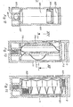
- the container 1 to 3 show a writing instrument with a refill.
- the container 1 consists of the front part 11, the middle part 12 and the head 13.
- the clip 14 is fastened to the middle part 12.
- the refill 2 is used interchangeably, consisting of the rigid housing 21, hereinafter also referred to as the primary storage space, and the tip 22.
- the tip 22 can be, for example, a capillary plastic tip, a fiber tip or a ballpoint pen tip.
- the lead 2 is pressed by a helical compression spring 121 against the stop 118 in the front part 11 of the housing.
- the tip 22 extends into the capillary space 201 of the mine, which is hereinafter referred to as the secondary storage space and is divided by concentric plastic cylinders which form cylindrical capillaries with a thickness of preferably 0.1-0.2 mm between their walls and communicate with one another.
- These cylinders are not shown in the drawing, since such capillary bodies as well as capillary bodies wound at a distance and capillary bodies consisting of disks perpendicular to the axis and at a capillary distance are known.
- This cylinder 202 is liquid-tight with an electrical connection through the lead housing 21 and forms with the housing wall 21 a capillary gap, the ink level is measured.
- the entire capillary space is connected to the outside air through the opening 203.
- a gas- and liquid-tight partition 204 divides the mine into the small-volume secondary capillary space 201 and the large-volume primary, pressurized ink supply space 210.
- a reload valve 230 is inserted tightly in this wall 204.
- the valve 230 includes a valve seat 231 on which a sealing ring or a sealing washer 232 lies.
- the spring 233 which is supported on a cap 234, presses the tappet 235 with the valve plate 236 in a sealing manner against the valve set 231 and the seal 232.
- the end of the plunger 235 projecting into the capillary space 201 carries a stop plate 237 for levers 238, which are actuated by the ferromagnetic ring plate 239 and an electromagnet 111 in the container tip 11.
- the ink is supplied from the ink chamber 210 to the valve seat 231 by a capillary Archimedean spiral, which is worked into the underside of a plastic base plate 211 in the form of a groove.
- the groove opens on the wall of the mine housing in the opening 212, into which an upwardly open capillary 213 with side openings 214 is sealingly inserted.
- the primary ink space 210 is filled with ink and an ink-immiscible propellant, such as isobutane or a fluorocarbon.
- the stocking 215 sucks full of ink the first time the refill is filled and, as a semi-permeable membrane, prevents gaseous propellant from penetrating the capillary. 2 shows the opening of the capillary on the valve side at the opening 216.
- An annular horseshoe electromagnet 111 rests in the container tip 11. This construction ensures that the gap between the ferromagnetic plate 239 and the electromagnet 111 is as small as possible.
- Stainless steel half-shells 112 which are resiliently mounted between the lead wall 21 and the container tip 11 in this area, with a sponge rubber ring 113, form the pair of capacitor plates with the cylinder 202 in the lead.
- the spring contact 114 for the inner x-capacitor document, ie the cylinder 202, is fastened to the bottom of the container tip 11.
- the spring contact 114, the capacitor cover 202 and the electromagnet 111 are electrically conductively connected to contact springs or pins 115.
- the contacts 115 establish the torsion between the writing element with the sensor in the front part of the writing instrument and the electrical components (power source, control circuit) arranged in the rear part of the writing instrument.
- the container tip 11 is mechanically connected to the central part 12 of the writing instrument by means of a cam lock, for example by the cams 116 protruding into the container recesses 122.
- a cam lock for example by the cams 116 protruding into the container recesses 122.
- An asummetric arrangement of these cams 116 ensures that no incorrect connections of the contacts 115 can occur with the counter contacts 123 arranged in the rear part of the writing instrument.
- the container recesses 122 also serve to ventilate the container space. The latter is important for the function in embodiments according to FIG. 10 and in all lead and cartridge designs which work with a mechanically compressible ink space.
- the mating contacts 123 are electrically conductively connected to a circuit board 124, which is located in the upper space of the middle part 12 of the writing instrument and is separated by the partition 124 and carries all electrical circuits outside the IC housing 126.
- IC housing 126 and circuit board 124 are held by the clamping ring 127.
- the optical or acoustic signal element 128 signals when the refill 2 no longer contains ink or the current source 129 in the rear part of the writing instrument no longer supplies sufficient current.
- the battery or accumulator 129 is held in contact by the circuit board 124 and the spring 131 which is supported in the rear end of the writing instrument.
- FIG. 16 The principle of the manual writing device according to the invention described above with reference to FIGS. 1 to 3 and also of the writing devices to be described below is schematically illustrated in FIG. 16.
- the pressurized writing fluid 901 in the primary storage container 21 is fed into the front capillary as required by a valve 902, ie the reload valve 230 in FIG. 1, which is closed by a spring and / or the pressure on the ink room 903, ie metered into the secondary storage room 201.
- the metering takes place via a sensor 904, ie the capacitor 112/202, the capacitance of which depends on the filling of the secondary storage space 201.
- the sensor 904 detects the ink filling of the secondary storage space 201 and gives the commands for opening and closing the electromagnetic valve 902 via a switching mechanism 905 (in FIGS. 1, 124 and 126).
- a battery or an accumulator 906 (in FIG. 1, 129) supplies the electrical energy.
- 907 symbolizes the signal transmitter designated by 128 in FIG. 1, for example LED.
- 908 indicates the opening of the capillary space 903 to the atmosphere. This is in contrast to the closed pressure chamber 909 of mine 2. It is conceivable to only get by with an opening command and to initiate the closure via a timer. This method has the disadvantage that the opening interval must be kept short in order to avoid an overflow of the capillary space. Maximum pressure must be expected. However, if the pressure is relatively low, e.g. if the ink supply in the cartridge or refill is almost exhausted, the pump strokes accumulate and the valve may flutter.
- a capacitive sensor is used as an example in the embodiments, which allows a quantitative measurement of the filling volume of the capillary space.
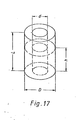
- the capacitance is given by the equation: In the above equation, the following are
- the initial capacitance C o is 4 - 20 pF.
- 1 mm ink height means a change in capacity from 8 x Co ⁇ 8 - 80 pF.
- L is chosen with 1 cm to 2 cm and ln (D / d) between 0.05 - 0.2.
- a circuit of FIG. 18 is used and the change in capacitance is measured digitally by detuning an oscillating circuit.
- the measuring capacitance C can be applied as an additional burden capacitance in series to a three-pole bending oscillator in the quartz oscillator Q01.
- 1 Hz with a basic frequency of 16384 Hz corresponds e.g. about 5 pF.
- a clock oscillator Q02 with exact frequency 16384 Hz and a counter ZT as a timer, the difference between the frequency of Q01 and Q02 can be formed in the counter ZR, a reversible counter with zero-crossing circuit, and as a measure of the capacity and thus the filling of the capillary space serve with ink.
- This difference in the counter ZR is determined in predetermined clock characters TR and is given via the gates 1 ... n in the buffer P, in which it is present in the integrating measuring intervals and, via a digital-analog converter DA, the switching mechanism S for controlling the solenoid valve 902 is available.
- FIGS. 1 to 3 show, with partial use of the previously used reference numerals, modified versions of FIGS. 1 to 3 likewise with interchangeable refills.
- gas space 223 and ink space 220 in the primary reservoir are separated by piston 221.
- the displaceable piston 221 is pressed against the ink by the gas in the space 223.
- the piston 221 is sealed against the container wall of the mine container 21 by the O-rings 222.
- the reload valve inserted into the partition 204 is also designed differently.
- the valve body 240 with the valve seat 241 and the seal 242 is at the same time, with its part pointing towards the writing tip, the inner capacitor surface.
- the radial bores 259 and central bore 258 force the ink into the inner capillary space 201, i.e. to the secondary reservoir.
- the part of the valve tappet 245 in the capillary space with the valve plate 246 is designed as a double piston, as shown in FIGS. 6 and 7 on an enlarged scale.
- the illustrations according to FIGS. 6 and 7 differ from FIG. 4 insofar as the angular bore 258/259 is replaced by four axial bores 255 which act in the same way but are easier to manufacture.
- the remaining design of the valve is identical to the first described embodiment.
- the double piston 251/253 axially connected to valve tappet 245 runs sealed with O-rings 252/254 in the inner bore of the valve body 240.
- the three pressure levers 248 engage on the end face 247 of the cylinder part 251 and are rotatable in the axis 250 and in the Recess 256 are performed.
- the spring 243 and the fluid pressure keep the valve closed as long as the levers 248 do not lift the valve plate 246. If the ferromagnetic disk 240 is pressed against the levers 248 when the electromagnet 111 is switched on, the valve opens as long as the electromagnet is energized.
- the spring 243 finds its second stop ring 244.
- the ink is supplied to the valve by capillary grooves in the stop ring 244 and through the space between the tappet 245, and the valve body 240 and the spiral spring 243.
- FIG 8 and 9 show an embodiment with a writing element permanently installed in the housing tip 411, for example a writing nib 417, a permanently installed sensor 422/423, a permanently installed valve with actuation 424-432 and an ink cartridge 600.
- the valve guide according to FIG 8 is the biasing spring 429 in the Capillary space relocated. It finds its stop on the one hand on the disc 430, which is firmly connected to the push rod 427, and on the other hand on the bush 431, which has a tight fit in the valve housing 423.
- the part of the valve housing 423 which produces the pressure-tight connection to the cartridge 600 protrudes from this end.
- the end of the tube 423 is suitably designed: For example, if a ball serves as a closure for the cartridge, through an insert 434 with deep axial grooves, so that the ink is not blocked when the ball rests on it. So that the internal pressure does not push the ink cartridge 600 out of its seat, the latter is screwed into the front part 411 with a threaded bush 418 in the front part 411 and a thread core 603 on the cartridge neck. The sealing ball 601 is raised and the ink can enter the valve body 423 through the neck 602 with the grooves 607.
- the capillary space is vented through the opening 415, the pre-chamber 416 and the channel 438 into the space 439.
- the ink is fed to the spring through the capillary 436 via the feeder 435, which fixes the spring 417 in the front part 411.
- the feeder is sealed onto the stop groove 413 in the front part 411 by means of the O-ring 414.
- FIG. 10 With this functional system, you only want to use the hydrostatic pressure of the ink liquid without additional pressure work, an embodiment according to FIG. 10 can be used. It is necessary to ensure air pressure compensation between the interior of the cartridge and the outside atmosphere during the reloading process of the capillary space, that is to say during the opening time of valve 526. The latter occurs through the valve 527, the valve plate 528 of which is raised at the same time as the valve 526, since both are controlled together by the ferromagnetic plate 532 and the magnet 533. Plate 532 is rigidly connected to valve 527 by three rods 534. The vent valve 527 is releasably connected to the three rods 534 to allow the cartridge to be changed.
- the air valve 527 has a sensor 536 for ink, for example a small absorbent felt ring, behind the valve plate in front of the air openings 535. If this is wetted with ink, ie the device is written in this writing position, in which its axis intersects the horizontal and the nib is above the horizontal, ink can escape at valve 528, reach the sensor and valves 526 and 527 close .
- This sensor can, for example, be switched as an electrical resistance, which decreases when the ink as electrolyte bridges the distance in the felt ring between two insulated contacts 537 and 538. Such a system without additional pressure can only write in this position above the horizontal as long as ink is available in the capillary space.
- FIG. 12 shows a cartridge 600 with a movable pressure piston 604 which separates the propellant gas space 605 from the ink space 606.
- the cartridge is sealed with a ball 601 in the neck 602.
- To insert the cartridge it is screwed into the thread 603, for example Container part 411 screwed with threaded part 418.
- the ball 601 is raised by means of the tube 423 with the insert 434 and the ink flow is ensured by the grooves 607 in the neck 602.
- the pressure is mechanically applied to the ink.
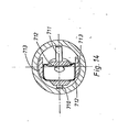
- the two springs 710/711 compress the ink-filled sack 712, which is suspended in the cartridge housing 713.
- the 15 shows a bellows cartridge.
- the bellows 822 is compressed by the spring 821.
- the springs 821 or 710/711 can be located on the cartridge housing, but they can also be attached to the container 12 or to the housing tip 11.
- a metal sleeve 611 encloses the actual ink space 612, the propellant gas space 613 and the movable pressure piston 614, the ink space 612 and the propellant gas space 613 separates from each other and can follow the decreasing ink level in ink consumption.
- the metal sleeve 611 is connected to the outside air at the rear end face via an opening 615.
- a piston element 616 is used, which rests with an annular seal 617 on the inner wall of the metal sleeve 611 and is held by an abutment plate 618, which holds the end flanging of the sleeve 611.
- the ink space is closed at the bottom by a valve piston which operates in the manner of a tappet and which a spring presses into its valve seat.
- a valve body 621 provided with a plunger 620 is accommodated in a separate housing 619 at the lower end of the ink cartridge 610 and is pressed against the valve seat 623 by a compression spring 622.
- the valve arrangement 621/623 is located in a valve housing 619, which is inserted into the metal sleeve 611 with an annular seal 625.
- a hat-shaped abutment 626 for the compression spring 622 is located within the valve housing 619.
- the compression spring 622 acts on the valve tappet 620 via a spring abutment 627.
- the ink On its way to the capillary ink space, the ink can reach valve 621/623 from ink space 612 via bore 628, past spring 622, spring abutment 627 and valve tappet 620.
- a rotary valve is used in the embodiment according to FIGS. 19 to 21.
- the aforementioned tappet 620 now forms an axis about which the valve body 621 can rotate.
- the rotary movement of the plunger 620 and the valve body 621 takes place by means of an electrical excitation winding 629 arranged on the outside of the valve housing 619, which can be actuated by the sensor with the battery installed in the writing instrument in such a way that the valve body 621 rotates once through 360 °.
- the excitation winding 629 acts on a permanent magnetic rotor 630, which is connected in a rotationally fixed manner to the valve tappet serving as axis 620 is.
- the front end face of the valve body 621 has the shape of a flat cone which, however, as shown in FIG. 20, is interrupted by a sector of, for example, 120 °.
- the valve seat 623 is also formed with the same cone angle as a circular conical depression, which, however, extends over the entire circumference and is only interrupted by a bore 631, which communicates with the capillary ink space in the manner already described.
- the valve seat 623 is located at the front end of a plug 632 which is inserted into the valve housing 619 and which penetrates the essentially cylindrical valve housing 619 at two opposite ends, as shown in FIG. 21.
- the ink cartridge with the built-in valve 621/623 works in such a way that the valve body 621 closes the bore 621 in the rest position (differently than shown in FIGS. 19 and 20).
- the excitation winding is excited so that the permanent magnetic rotor 630 makes a full revolution.
- the rotor 630 also passes through the position shown in FIG. 20, so that the ink from the ink space 612 can reach the bore 631.
- the recess 633 in the front end face of the valve body 621 which can be seen in FIGS. 19 and 20, is selected in relation to the rotational speed of the rotor 630 within the ink liquid so that the required amount of refill ink can pass through.
- the rotor 630 is stopped after each movement in such a way that an end face of the valve body 621 closes the bore 631.
- the writing instrument according to the invention shown in FIGS. 22a and 22b to be placed one below the other also works for actuating the recharging valve with a rotating electric motor, but not with a lifting magnet, which experience has shown that it consumes and consumes considerably more electrical energy.
- a rear tubular casing part 301 consists of a rear tubular casing part 301 and a front tubular casing part 302, which can be closed at the front end in a conventional manner with a cap 300 covering the spring 303.
- the ink cartridge 304 which is formed by a metal sleeve provided with a closed bottom, is located within the casing sleeve 301.
- the movable pressure piston 305 which separates the pressure gas space 306 from the ink space 307, is located in this metal sleeve.
- the front end of the ink cartridge 301 is closed with a valve insert 308.
- a corresponding crimp 312 of the cartridge 304 holds the insert 308.
- the rear jacket part 301 is detached from the front jacket part 302 on the screw thread 309.
- the ink cartridge 304 can then be screwed in with the thread 313 provided on the valve insert 308.
- a filled, ie pressurized, ink cartridge is closed by means of the valve ball 311, which lies in the valve seat 314 of the valve insert and is held in place there. If such a cartridge is screwed into a writing instrument, as shown in FIG. 22a, the pusher tube 310 firmly anchored in the writing instrument pushes the sealing ball 311 out of the valve seat 314.
- the pusher tube 310 is not completely covered, so that the ink from the ink space 307 past the sealing ball 311 can reach the interior of the pusher tube.
- the arrangement is such that the sealing ball 311 is pressed back into its valve seat 314 by the pressure prevailing in the ink cartridge and keeps the cartridge closed. The prerequisite for this is that the ball 311 cannot move too far from the valve seat 314.
- a recess 315 is provided in the valve insert 308, which receives the valve ball 311 when the valve is open.
- a plug 316 is provided opposite the valve seat 314, which closes the recess 315 to such an extent that the ball 311 cannot escape and remains in the vicinity of its valve seat 314.
- an inner metal housing 317 which receives the bearing plug 318 provided with a nut thread 313 in a form-fitting manner.
- This plug 318 is held with flanges or beads.
- the push tube 310 Inside the preferably two-part plug 318 is the push tube 310, which can penetrate the central bore of the valve insert of the cartridge in order to displace the closure ball 311 from its seat 314.
- the ink can flow through the interior of tube 310 reach a line fork 319, to which spirally wound steel tubes 321 are connected for the further transport of the ink to the capillary store 320, which, in the manner to be described below, also have the task of holding the reload valve in the valve seat.
- the chamber 322 is closed Recording of the dry cell 323, with which the sensor electronics are fed and the valve actuation mechanism is energized.
- the electrical connection of the battery 323 can be carried out in the usual way via metallic housing parts or corresponding lines.
- Below the battery space 322 is separated by a partition 324 and sealed with an annular seal 325, the integrated circuit, ie the IC board 326, which operates in the manner described above to actuate the reload valve according to the control of the sensor.
- the battery 322 also serves to drive an electric motor 327, which is located under the IC board 326.
- the motor shaft 328 protruding from the front of the electric motor 327 is connected to a sleeve 329, which can rotate in a coaxial manner in the bore 330 of a further housing plug 331.
- the plug 331 is also fixed in the aforementioned metal pipe 317.
- a circumferential roller track 332 is formed in this stopper 331 for a roller 333 which is mounted in the sleeve 329 with a transverse axis 334.
- the roller conveyor 332 is guided in the axial direction in such a way that the roller 333 is moved back and forth in the axial direction during a full revolution.
- the sleeve 329 is rotatably mounted with the motor axis 328, but is also axially displaceably mounted, so that the sleeve also performs an axial forward and return stroke when the roller 333 rotates fully
- FIG. 23 shows that the steel tubes 321 acting as a spring extend further downward outside the roller conveyor 332 into the guide disk 334 shown in section in FIG. 24, within which the two steel tubes 321 are connected again via a transverse bore 335, and then an axial bore 336 to dine.
- the guide washer is suspended with a pin 337 and a washer 338 in the perforated bottom of the sleeve 329.
- the axial extension on the opposite side contains the axial bore 336 and at the front end the valve body 339, which together with the valve seat 340 forms the reload valve for the capillary space 320.
- the spiral steel tubes 32 press the guide disk 334 down and thus the conical valve body 339 into the conical valve seat -340, which is located in a further housing plug 341, which is also inserted into the metal sleeve 317.
- an amount of ink measured in accordance with the restricted cross-sections from the ink space 307 can reach the outlet bore 342 of the valve seat 340 and feed the capillary system 320, which is connected in a conventional manner to the nib 303.
- a tube writing tip 344 is provided, which is screwed onto the front end of the front casing sleeve 302, which is provided with a thread 346, with a corresponding casing 345.
- the writing tube insert has a connection to the capillary storage 320.
- FIGS. 27 and 28 show two different embodiments of a writing instrument according to the invention with regard to the accommodation of the ink cartridge and the dry cell.
- the casing sleeves of the writing instrument must be able to be taken apart at appropriate points.
- the clip 350 is located at the rear end of the writing instrument. At the front end there is only a small cap 351 surrounding the nib, which, however, cannot be plugged onto the rear end of the nib as is usually the case with fountain pens.
- the battery 352 In the cavity at the rear end of the writing instrument, in the area of the clip 350, there is the battery 352, which is separated from the exchangeable ink cartridge 354 by a partition 353. The electrical connections to the battery 352 are to be routed past the ink cartridge 354 here, but this results in a shorter line system between the ink reservoir and pen.
- a possibility must be created for the jacket sleeve in the area of the cartridge screw-in nut thread in order to separate the jacket sleeves of the writing instrument from one another.
- FIG. 27 is practically the writing instrument according to FIG. 22 with the exception that the position of the ink cartridge and dry battery are interchanged.
- the writing instrument clip 360 is located in the usual way on the spring-covering cap 361. In this embodiment, it is not difficult to insert a new ink cartridge 364 after the writing instrument shell parts have been taken apart, but a person skilled in the art will generally be consulted need to replace the battery 362 between the electric motor 363 and ink cartridge seat 365. Here too, the writing instrument largely corresponds to the construction according to FIG. 22.
Landscapes
- Engineering & Computer Science (AREA)
- Mechanical Engineering (AREA)
- Pens And Brushes (AREA)
Priority Applications (1)
| Application Number | Priority Date | Filing Date | Title |
|---|---|---|---|
| AT83103215T ATE44262T1 (de) | 1982-06-02 | 1983-03-31 | Tintenversorgungssystem fuer mit fluessiger tinte arbeitende schreibgeraete. |
Applications Claiming Priority (2)
| Application Number | Priority Date | Filing Date | Title |
|---|---|---|---|
| DE19823220750 DE3220750A1 (de) | 1982-06-02 | 1982-06-02 | Tintenversorgungssystem fuer mit fluessiger tinte arbeitende schreibgeraete |
| DE3220750 | 1982-06-02 |
Publications (3)
| Publication Number | Publication Date |
|---|---|
| EP0096177A2 true EP0096177A2 (fr) | 1983-12-21 |
| EP0096177A3 EP0096177A3 (en) | 1984-07-04 |
| EP0096177B1 EP0096177B1 (fr) | 1989-06-28 |
Family
ID=6165092
Family Applications (1)
| Application Number | Title | Priority Date | Filing Date |
|---|---|---|---|
| EP83103215A Expired EP0096177B1 (fr) | 1982-06-02 | 1983-03-31 | Système d'alimentation pour instrument à écrire avec encre liquide |
Country Status (5)
| Country | Link |
|---|---|
| US (1) | US4573819A (fr) |
| EP (1) | EP0096177B1 (fr) |
| JP (1) | JPS5941300A (fr) |
| AT (1) | ATE44262T1 (fr) |
| DE (2) | DE3220750A1 (fr) |
Cited By (6)
| Publication number | Priority date | Publication date | Assignee | Title |
|---|---|---|---|---|
| FR2580234A1 (fr) * | 1985-04-17 | 1986-10-17 | Mitsubishi Pencil Co | Instrument pour ecrire, peindre ou analogue |
| FR2585628A1 (fr) * | 1985-02-20 | 1987-02-06 | Mitsubishi Pencil Co | Instrument d'ecriture du type feutre |
| FR2661135A1 (fr) * | 1990-04-24 | 1991-10-25 | Rotring Werke Riepe Kg | Petit tube d'ecriture, notamment pour l'utilisation dans un appareil a dessiner. |
| FR2704183A1 (fr) * | 1993-04-19 | 1994-10-28 | Rotring Int Gmbh | Instrument d'écriture ou de dessin. |
| DE10054599C1 (de) * | 2000-11-03 | 2002-04-18 | Hahn Schickard Ges | Dosiervorrichtung und Schreibgerät mit einer Dosiervorrichtung |
| DE10054597B4 (de) * | 2000-11-03 | 2006-02-09 | Gebr.Schmidt Gmbh & Co.Kg | Vorratstank für ein Dosiersystem und Dosiersystem |
Families Citing this family (15)
| Publication number | Priority date | Publication date | Assignee | Title |
|---|---|---|---|---|
| CA1299553C (fr) * | 1987-03-11 | 1992-04-28 | Ruben Nevarez | Methode et dispositif d'amorcage pour plume a jet d'encre |
| GB2215672B (en) * | 1988-03-23 | 1992-02-05 | Mitsubishi Pencil Co | Writing instrument with ink quantity or level detecting function. |
| DE4135605A1 (de) * | 1991-10-29 | 1993-05-06 | Rotring-Werke Riepe Kg, 2000 Hamburg, De | Schreib- oder zeichengeraet |
| DE4431751C1 (de) * | 1994-09-06 | 1996-05-09 | Siemens Ag | Flammwidriges einkomponentiges Reaktionsharz |
| DE29819071U1 (de) * | 1998-10-20 | 2000-03-02 | Anderka, Gerold, 25474 Ellerbek | Handschreib- oder -auftraggerät |
| US20070045337A1 (en) * | 2005-06-24 | 2007-03-01 | Hornsby James R | Dispensing device |
| WO2007050638A1 (fr) * | 2005-10-24 | 2007-05-03 | Jakks Pacific, Inc. | Appareil de distribution de liquide musical |
| DE102006013920A1 (de) * | 2006-03-25 | 2007-09-27 | Diplomat Cunewalde Gmbh | Tintenschreibgerät und Verfahren zur Steuerung des Tintenflusses an der Schreibfederspitze |
| CA2701437C (fr) * | 2009-04-29 | 2014-12-09 | Laricina Energy Ltd. | Methode de production d'hydrocarbures visqueux comprenant l'injection cyclique de vapeur et de solvant |
| TWI467228B (zh) * | 2012-11-30 | 2015-01-01 | Nat Univ Chung Hsing | An electric wetting element and its making method |
| CN105835564A (zh) * | 2016-06-17 | 2016-08-10 | 王芊霖 | 一种自动补液的记号笔 |
| CN109890624A (zh) * | 2016-10-28 | 2019-06-14 | G·R·詹吉尔 | 可再填充的书写工具 |
| DE202018000858U1 (de) * | 2018-02-19 | 2019-05-22 | Stabilo International Gmbh | Gerät zum manuellen Auftragen einer Flüssigkeit |
| CN110816125B (zh) * | 2018-08-07 | 2021-03-12 | 深圳普赢创新科技股份有限公司 | 墨水型位置指示装置 |
| CN119872121A (zh) * | 2025-03-26 | 2025-04-25 | 温州凯文文体用品制造有限公司 | 一种出墨可控的环保型直液笔 |
Family Cites Families (19)
| Publication number | Priority date | Publication date | Assignee | Title |
|---|---|---|---|---|
| GB190905475A (en) * | 1909-03-06 | 1909-12-02 | Peter Albig | Improved Fountain Pen. |
| US1428079A (en) * | 1921-09-20 | 1922-09-05 | Clark Thad | Pen |
| US2222824A (en) * | 1940-08-20 | 1940-11-26 | John D Rossier | Magazine type pencil |
| US2509465A (en) * | 1946-03-18 | 1950-05-30 | Russell T Wing | Dual-well fountain pen |
| US2567618A (en) * | 1949-11-08 | 1951-09-11 | Hadly W Quaintance | Fountain pen |
| DE926054C (de) * | 1950-07-13 | 1955-04-04 | Ehrenreich Haeuselmann | Fuellschreibgeraet mit in der Spitzenbohrung des Halters des Geraetes axial verschiebbar gelagertem Schreibroehrchen und gesteuertem Schreibgutfluss |
| US2762337A (en) * | 1952-12-04 | 1956-09-11 | Parker Pen Co | Writing instruments |
| CH355053A (de) * | 1957-08-16 | 1961-06-15 | Albertini Sauro | Schreibgerät mit hülsenförmigem Tintenbehälter |
| FR1306685A (fr) * | 1961-09-05 | 1962-10-19 | Christian Sa Ets | Perfectionnement apporté aux stylographes |
| FR1481451A (fr) * | 1966-05-18 | 1967-05-19 | Stylographe pour tracer en relief | |
| CH572815A5 (en) * | 1972-06-26 | 1976-02-27 | Ananda Anlageanst | Ball point pen cartridge - has ink column enclosed by free piston to form pressurised gas chamber |
| DE2255495C2 (de) * | 1972-11-13 | 1975-01-02 | Guenther Wagner Pelikan-Werke Gmbh, 3000 Hannover | Füllschreibgerät für flüssige Schreibmedien |
| JPS5114424A (en) * | 1974-07-26 | 1976-02-04 | Seiko Instr & Electronics | Jidoseizukitono penshirusochi |
| US4318626A (en) * | 1977-11-15 | 1982-03-09 | Edward Bok | Pen with an improved ink injection system |
| JPS55121097A (en) * | 1979-03-13 | 1980-09-17 | Pilot Pen Co Ltd | Fountain pen |
| JPS5627398A (en) * | 1979-08-14 | 1981-03-17 | Pilot Pen Co Ltd | Fountain pen |
| EP0015784B1 (fr) * | 1979-03-13 | 1984-01-18 | Pilot Man-Nen-Hitsu Kabushiki Kaisha | Stylographe |
| JPS5845101Y2 (ja) * | 1979-05-15 | 1983-10-13 | ぺんてる株式会社 | ノック式シャ−プペンシル |
| DE2944512A1 (de) * | 1979-11-03 | 1981-05-14 | Pelikan Ag, 3000 Hannover | Tintenbehaelter mit kapazitiver fuellstandsanzeige |
-
1982
- 1982-06-02 DE DE19823220750 patent/DE3220750A1/de not_active Ceased
-
1983
- 1983-03-31 AT AT83103215T patent/ATE44262T1/de not_active IP Right Cessation
- 1983-03-31 DE DE8383103215T patent/DE3380119D1/de not_active Expired
- 1983-03-31 EP EP83103215A patent/EP0096177B1/fr not_active Expired
- 1983-06-02 JP JP58097045A patent/JPS5941300A/ja active Pending
- 1983-06-02 US US06/500,257 patent/US4573819A/en not_active Expired - Lifetime
Cited By (9)
| Publication number | Priority date | Publication date | Assignee | Title |
|---|---|---|---|---|
| FR2585628A1 (fr) * | 1985-02-20 | 1987-02-06 | Mitsubishi Pencil Co | Instrument d'ecriture du type feutre |
| FR2580234A1 (fr) * | 1985-04-17 | 1986-10-17 | Mitsubishi Pencil Co | Instrument pour ecrire, peindre ou analogue |
| FR2661135A1 (fr) * | 1990-04-24 | 1991-10-25 | Rotring Werke Riepe Kg | Petit tube d'ecriture, notamment pour l'utilisation dans un appareil a dessiner. |
| US5336007A (en) * | 1990-04-24 | 1994-08-09 | Koh-I-Noor Inc. | Plotter pen with indicator circuit |
| FR2704183A1 (fr) * | 1993-04-19 | 1994-10-28 | Rotring Int Gmbh | Instrument d'écriture ou de dessin. |
| DE10054599C1 (de) * | 2000-11-03 | 2002-04-18 | Hahn Schickard Ges | Dosiervorrichtung und Schreibgerät mit einer Dosiervorrichtung |
| WO2002036361A1 (fr) | 2000-11-03 | 2002-05-10 | Schmidt Feintechnik Gmbh | Dispositif de dosage et instrument d'ecriture pourvu d'un tel dispositif |
| DE10054597B4 (de) * | 2000-11-03 | 2006-02-09 | Gebr.Schmidt Gmbh & Co.Kg | Vorratstank für ein Dosiersystem und Dosiersystem |
| US7093994B2 (en) | 2000-11-03 | 2006-08-22 | Gebr. Schmidt Fabrik fur Feinmechanik, GmbH & Co. Kg | Dosing device and writing implement with a dosing device |
Also Published As
| Publication number | Publication date |
|---|---|
| DE3220750A1 (de) | 1983-12-08 |
| JPS5941300A (ja) | 1984-03-07 |
| EP0096177B1 (fr) | 1989-06-28 |
| ATE44262T1 (de) | 1989-07-15 |
| US4573819A (en) | 1986-03-04 |
| EP0096177A3 (en) | 1984-07-04 |
| DE3380119D1 (en) | 1989-08-03 |
Similar Documents
| Publication | Publication Date | Title |
|---|---|---|
| EP0096177B1 (fr) | Système d'alimentation pour instrument à écrire avec encre liquide | |
| EP0016408B1 (fr) | Détecteur de dureté pour une installation d'adoucissement de l'eau et installation pour adoucir l'eau | |
| DE2705069A1 (de) | Markiervorrichtung mit dreiphasen- tintenkreislauf | |
| DE4443187B4 (de) | Kugelschreiber | |
| DE4015586C2 (de) | Gerät zum Auftragen von Schreib-, Zeichen-, Druck- oder Malflüssigkeit auf einem Untergrund | |
| DE2208111A1 (de) | Schreibgeraet mit einer schreibspitze aus poroesem oder kapillarem werkstoff | |
| DE4323458A1 (de) | Vorrichtung zum Füllen von Schreib-, Zeichen-, Druck- oder Malgeräten | |
| CH652974A5 (de) | Fuellminenstift mit auswechselbarem minenvorratsbehaelter. | |
| DE2352677C2 (de) | Vorrichtung zum Dosieren von Chemikalienlösungen | |
| DE1548605C3 (de) | Mit Tinte arbeitendes Registriergerät | |
| EP1896267B1 (fr) | Instrument d'écriture destiné à la peinture, au dessin et au marquage | |
| DE2824155C2 (de) | Vorrichtung zur automatischen Entnahme von Flüssigkeitsproben, beispielsweise aus der Kanalisation | |
| DE10054597B4 (de) | Vorratstank für ein Dosiersystem und Dosiersystem | |
| WO2021249953A1 (fr) | Dispositif de pipetage à distribution déclenchée par le gaz-son de quantités de fluide de préférence comprises entre 10 et 500 nl | |
| DE3102346A1 (de) | "abfuellvorrichtung fuer fluessigkeiten" | |
| WO2007110042A2 (fr) | Instrument d'écriture à encre et procédé pour réguler le flux d'encre au niveau de la pointe de la plume d'écriture | |
| DE4410919C2 (de) | Nachfüllbehältnis für Schreib-, Mal-, Zeichen- bzw. Markiergeräte | |
| EP0149216A2 (fr) | Dispositif pour écrire | |
| EP1598212B1 (fr) | Instrument d'écriture, en particulier marqueur pour vernis | |
| DE850869C (de) | Schreibgeraet mit Kugelspitze und Tintenvorratsbehaelter | |
| DE3440813C2 (de) | Schreibgerät mit einem Vorratsbehälter für Schreibflüssigkeit | |
| EP1525460B1 (fr) | Dispositif et procede de production de pression dans l'electrolyte d'une electrode de reference | |
| DE2359629A1 (de) | Fuellhalter | |
| EP0691216B1 (fr) | Dispositif pour remplir un instrument à écrire, dessiner ou peindre | |
| DE1461625C (de) | Füllfederhalter |
Legal Events
| Date | Code | Title | Description |
|---|---|---|---|
| PUAI | Public reference made under article 153(3) epc to a published international application that has entered the european phase |
Free format text: ORIGINAL CODE: 0009012 |
|
| AK | Designated contracting states |
Designated state(s): AT BE CH DE FR GB IT LI LU NL SE |
|
| 17P | Request for examination filed |
Effective date: 19840125 |
|
| PUAL | Search report despatched |
Free format text: ORIGINAL CODE: 0009013 |
|
| AK | Designated contracting states |
Designated state(s): AT BE CH DE FR GB IT LI LU NL SE |
|
| RAP1 | Party data changed (applicant data changed or rights of an application transferred) |
Owner name: HERRNRING, GUENTHER, DR. |
|
| RIN1 | Information on inventor provided before grant (corrected) |
Inventor name: HERRNRING, GUENTHER, DR. |
|
| GRAA | (expected) grant |
Free format text: ORIGINAL CODE: 0009210 |
|
| AK | Designated contracting states |
Kind code of ref document: B1 Designated state(s): AT BE CH DE FR GB IT LI LU NL SE |
|
| PG25 | Lapsed in a contracting state [announced via postgrant information from national office to epo] |
Ref country code: SE Effective date: 19890628 Ref country code: NL Effective date: 19890628 Ref country code: IT Free format text: LAPSE BECAUSE OF FAILURE TO SUBMIT A TRANSLATION OF THE DESCRIPTION OR TO PAY THE FEE WITHIN THE PRESCRIBED TIME-LIMIT;WARNING: LAPSES OF ITALIAN PATENTS WITH EFFECTIVE DATE BEFORE 2007 MAY HAVE OCCURRED AT ANY TIME BEFORE 2007. THE CORRECT EFFECTIVE DATE MAY BE DIFFERENT FROM THE ONE RECORDED. Effective date: 19890628 Ref country code: GB Effective date: 19890628 Ref country code: FR Free format text: THE PATENT HAS BEEN ANNULLED BY A DECISION OF A NATIONAL AUTHORITY Effective date: 19890628 Ref country code: BE Effective date: 19890628 |
|
| REF | Corresponds to: |
Ref document number: 44262 Country of ref document: AT Date of ref document: 19890715 Kind code of ref document: T |
|
| REF | Corresponds to: |
Ref document number: 3380119 Country of ref document: DE Date of ref document: 19890803 |
|
| EN | Fr: translation not filed | ||
| GBV | Gb: ep patent (uk) treated as always having been void in accordance with gb section 77(7)/1977 [no translation filed] | ||
| PG25 | Lapsed in a contracting state [announced via postgrant information from national office to epo] |
Ref country code: LU Free format text: LAPSE BECAUSE OF NON-PAYMENT OF DUE FEES Effective date: 19900331 Ref country code: LI Effective date: 19900331 Ref country code: CH Effective date: 19900331 Ref country code: AT Effective date: 19900331 |
|
| PLBE | No opposition filed within time limit |
Free format text: ORIGINAL CODE: 0009261 |
|
| STAA | Information on the status of an ep patent application or granted ep patent |
Free format text: STATUS: NO OPPOSITION FILED WITHIN TIME LIMIT |
|
| 26N | No opposition filed | ||
| REG | Reference to a national code |
Ref country code: CH Ref legal event code: PL |
|
| PG25 | Lapsed in a contracting state [announced via postgrant information from national office to epo] |
Ref country code: DE Effective date: 19901201 |