EP0096294A2 - Positionierungsvorrichtung - Google Patents
Positionierungsvorrichtung Download PDFInfo
- Publication number
- EP0096294A2 EP0096294A2 EP83105150A EP83105150A EP0096294A2 EP 0096294 A2 EP0096294 A2 EP 0096294A2 EP 83105150 A EP83105150 A EP 83105150A EP 83105150 A EP83105150 A EP 83105150A EP 0096294 A2 EP0096294 A2 EP 0096294A2
- Authority
- EP
- European Patent Office
- Prior art keywords
- positioning device
- exposure
- pressure piece
- piston rod
- positioning
- Prior art date
- Legal status (The legal status is an assumption and is not a legal conclusion. Google has not performed a legal analysis and makes no representation as to the accuracy of the status listed.)
- Granted
Links
- 230000006835 compression Effects 0.000 claims description 13
- 238000007906 compression Methods 0.000 claims description 13
- 230000003584 silencer Effects 0.000 claims description 4
- 230000001105 regulatory effect Effects 0.000 claims description 3
- 238000000034 method Methods 0.000 description 2
- 230000005281 excited state Effects 0.000 description 1
- 238000004519 manufacturing process Methods 0.000 description 1
- 230000001960 triggered effect Effects 0.000 description 1
Images

Classifications
-
- G—PHYSICS
- G03—PHOTOGRAPHY; CINEMATOGRAPHY; ANALOGOUS TECHNIQUES USING WAVES OTHER THAN OPTICAL WAVES; ELECTROGRAPHY; HOLOGRAPHY
- G03F—PHOTOMECHANICAL PRODUCTION OF TEXTURED OR PATTERNED SURFACES, e.g. FOR PRINTING, FOR PROCESSING OF SEMICONDUCTOR DEVICES; MATERIALS THEREFOR; ORIGINALS THEREFOR; APPARATUS SPECIALLY ADAPTED THEREFOR
- G03F9/00—Registration or positioning of originals, masks, frames, photographic sheets or textured or patterned surfaces, e.g. automatically
Definitions
- the invention relates to a positioning device in an exposure / developing device for printing forms which are transported to an exposure table by means of a roller transport device, with devices for positioning the individual printing form.
- labeled and illustrated printing forms for example printing plates, which are suitable for printing immediately after exposure and development, takes place in such a way that the printing plates are first electrostatically charged and then an original is projected onto the individual printing plate. After this exposure process is completed, the printing plate is developed, fixed and stripped with a developer, after which it is ready for the printing process.
- a device for pulling in and transporting printing plates onto an exposure table using transport rollers is known.
- the uppermost of the printing plates stacked in a magazine is gripped by a swiveling lifting cylinder in this device and placed in a circular arc on a suction plate of the exposure table.
- the transport rollers are arranged on both sides of the suction plate, each of which has a drive roller in each row are driven by round cord transport rings.
- the transport rollers of each row which lie first in the transport direction of the printing plate, are arranged on swivel blocks which are pivoted outward from the rows before the printing plate is placed on, in order to enable the front part of the printing plate to be placed on the suction plate without jamming.
- the front transport rollers are pivoted onto the side edge of the pressure plate and this is transported forward, the side edges being guided in grooves in the transport rollers.
- the pressure plate is transported forward on the suction plate until it lies against a stop pin.
- the suction plate is subjected to negative pressure, as a result of which the pressure plate is held in its exposure position.
- the printing plate is charged by a corona and then the exposure.
- the stop pin is sunk so that the printing plate can be transported further by the transport rollers onto a development table.
- the printing plate is positioned only in the transport direction, i.e. in their longitudinal direction, but not laterally.
- German patent application P 31 22 321.4 a device for the feeding and transport of Printing plates on an exposure table with the help of rollers arranged in pairs, which are fastened on two roller strips by means of blocks, are proposed.
- the roller strips are arranged on both sides of the exposure table in the transport direction and the transport rollers lying first in the transport direction are mounted on swivel blocks which are swiveled outwards before the printing plate is attached and swiveled back in again after the printing plate has been placed on, so that together with the other rolls To take over plate transport.
- the pressure plate is transported forward on the suction plate until it rests against a stop that can be lowered into the suction plate.
- the printing plate After the printing plate is positioned by the stop, it is subjected to negative pressure so that it is held in its exposure position.
- positioning is carried out by means of a stop only in the transport direction of the pressure plate, ie in its longitudinal direction, but not laterally thereto.
- the roller strips in their entirety are pivoted away from the exposure table, parallel to themselves, so that the printing plate can be exposed unhindered up to its outer edges.
- the printing form is positioned only in the longitudinal direction by placing the front edge of the printing form against a stop, without the trailing edge of the printing form being aligned or on the Trailing edge a certain contact pressure is exerted towards the stop. Lateral positioning or alignment does not take place, but only guidance of the printing form by transport rollers, in the grooves of which the two longitudinal edges of the printing form move. A precise and reproducible alignment of the printing form on the exposure table is therefore only possible to a limited extent in the known devices.
- the object of the invention is to be able to align each printing form on an exposure table in the longitudinal and lateral directions in a reproducible manner and with great accuracy.
- a positioning device according to the preamble of claim 1 in that the device for side positioning consists of a pneumatically operated pressure piece and stop pins which are adjustably mounted on the exposure table and opposite the pressure piece that the device for longitudinal positioning one pneumatically operated slide and a stop for the leading edge of the printing form, and that both devices start positioning at the same time.
- the pressure piece consists of a cylindrical hollow bolt and a ring and is on a piston rod of a lifting cylinder stored, which is adjustable in a holder which is attached to a mounting plate.
- the pressure piece is expediently fastened to it by a pin which is guided in a slot in the bolt and passes through the piston rod.
- a compression spring is arranged inside the bolt, which presses the pressure piece against the pin in the rest position of the piston rod.
- the lifting cylinder is connected in an advantageous manner by a solenoid valve with a pressure line that the lifting cylinders with compressed air acts on at energized solenoid valve, which extends the piston rod in the direction D ruck form.
- the solenoid valve is connected to a throttle silencer through which the compressed air exits when the solenoid valve is de-energized.
- an adjustable adjustment rail is mounted on the mounting plate, on which a microswitch is arranged, the switching flag of which protrudes into the path of movement of the ring of the pressure piece.
- the device for longitudinal positioning of the printing plate te is designed such that the slide is guided in an elongated hole guide of the exposure suction table and is pivotally mounted about a bolt on a pressure piece.
- a bearing is expediently arranged on the underside of the exposure suction table, in which a lifting cylinder is adjustable, on the piston rod of which the pressure piece is seated, on the inside of which there is a compression spring.
- the piston rod is advantageously equipped with a bolt which is guided in an elongated hole of the pressure piece, and the end face of the piston rod bears against the compression spring.
- the advantage is achieved that the D also aligned smoothly form in both longitudinal and lateral directions with even pressure against stops, with great accuracy, is applied, said pressure being metered such that no damage to the edges of the printing plate occur.
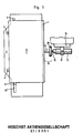
- the positioning device shown schematically in FIG. 1 consists of a device for lateral positioning and a device for longitudinal positioning of a printing form 1, for example a printing plate, which is transported to an exposure table 2 with the aid of a roller transport device (not shown).
- the device for the lateral positioning of the printing form 1 comprises a pressure piece 10 with a bolt 6 and stop pins 4, 4 ', which are opposite the pressure piece 10, separated by the width of the printing form 1.
- the exposure table 2 is an exposure suction table which is subjected to negative pressure as soon as the printing form 1 is positioned both in the longitudinal and in the lateral direction.
- the pressure piece 10 pushes the printing form 1 by means of the bolt 6 against the two stop pins 4, 4 'which are adjustably mounted on the exposure suction table 2.
- the device for the longitudinal positioning of the printing form 1, that is the orientation in the transport direction of the printing plate, consists of a slide 5 which is displaceable in an elongated hole guide 33 and a stop 3 for the front edge of the printing plate. t
- the slider 5 is initially pivoted downward so that the pressure plate can run over it without hindrance. As soon as the pressure plate has completely passed the slide 5, it pivots upwards, lies against the rear edge of the pressure plate and pushes it against the stop 3.
- the stop 3 for the front edge of the pressure plate is designed to be retractable. As soon as the pressure plate is sucked onto the surface of the exposure suction table 2, the stop 3, the slide 5 and the pressure piece 10 return to their respective starting position with the bolt 6 and the pressure plate is thus positioned for exposure.
- the pressure piece 10 consists of the cylindrical hollow bolt 6 and a ring 20 and is mounted on a piston rod 19 of a lifting cylinder 15.
- the pressure piece 10 is fastened on the piston rod 19 by a pin 7 which is guided in a slot 8.
- a compression spring 9 inside the bolt 6 holds the pressure piece 10 pressed against the pin 7 in the rest position.
- the lifting cylinder 15 is adjustable in a holder 17 which is fastened on a mounting plate 16. Depending on the width of the printing plates to be processed, the lifting cylinder 15 is displaced in the holder 17.
- the lifting cylinder 15 is connected via a solenoid valve 13 to a pressure line, which acts on the lifting cylinder 15 with compressed air 18 when the solenoid valve is energized.
- the compressed air flowing into the lifting cylinder 15 extends the piston rod 19 to the full stroke length.
- the pressure piece 10 is taken along and the front edge of the bolt strikes the longitudinal edge of the pressure plate 1.
- the pressure plate is now moved laterally up to the opposite fixed stop pins 4,4 '.
- the piston rod 19 continues to the full stroke length and compresses the compression spring 9 men, the pin 7 is moved in the slot 8 towards the pressure plate.
- the pressure plate is only pressed by the spring 9 via the bolt 6 of the pressure piece 10 against the two fixed stop pins 4, 4 ', the spring 9 cushioning the piston rod 19 extended to the full stroke length so that the contact of the bolt 6 with the longitudinal edge the pressure plate 1 is elastic and not rigid. This ensures that the piston rod 19 is not damaged by the piston rod 19 extended to the full stroke length.
- the solenoid valve 13 is equipped with a throttle silencer 14, through which the compressed air 18 can escape without great noise when the solenoid valve 13 is de-energized and by means of which the piston movement can be regulated. As soon as the solenoid valve 3u is de-energized, the negative pressure on the exposure suction table 2 is released so that the pressure plate 1 can be removed from the exposure suction table 2.
- the longitudinal positioning which will be described below with reference to FIGS. 2 and 3, begins simultaneously with the side positioning.
- an adjustable setting rail 12 is mounted, on which a microswitch 11 is attached, the switching tab 35 of which protrudes into the path of movement of the ring 20.
- the ring 20 actuates the switching flag 35 of the microswitch 11.
- the microswitch 11 excites a further solenoid valve 36, which is shown in FIG 3 is shown.
- a vacuum suction head 37 which is connected to the exposure suction table 2 is pressurized with compressed air 22. In this case, vacuum or suction air is created in the vacuum suction head 37, as a result of which the pressure plate 1 is sucked onto the surface of the exposure suction table 2.
- a vacuum switch (not shown) switches off the solenoid valve 13 if the vacuum continues, so that the compressed air 18 can escape through the throttle silencer 14 of the solenoid valve 13.
- the lifting cylinder 15 is no longer acted upon by compressed air, so that a return spring, not shown, in the lifting cylinder can pull the piston rod 19 and with it the pressure piece 10 back into the starting position.
- the pressure plate 1 is then sucked in and positioned for exposure on the exposure suction table 2.
- the device for longitudinal positioning of the printing plate 1 is described in more detail below with reference to FIG. 3.
- the slider 5 is guided in the slot guide 33 of the exposure suction table 2 and ge about a bolt 34 on a pressure piece 28 pivotable stores.
- the printing plate 1 runs during transport on the exposure suction table 2 via the slanted slider 5 of the device for longitudinal positioning.
- a bearing 24 is arranged on the underside of the exposure suction table 2, in which a lifting cylinder 23, which is similar to the lifting cylinder 15 for the side positioning, is adjustable.
- the pressure piece 28 sits on the piston rod 25 of the lifting cylinder 23, inside which there is a compression spring 29.
- a solenoid valve 21 is excited and the piston rod 25 is pressed to the right by means of compressed air 22.
- a stop plate 26 is arranged on the underside of the exposure suction table 2 and protrudes into the slot guide 33 of the exposure suction table 2.
- the stop plate 26 is angled and when retracting the piston rod 25 of the lifting cylinder 23, i.e. 3 to the left, the slide 5 is pressed against the stop plate 26 and pivoted obliquely downward about the bolt 34.
- the end face of the slide 5 is chamfered and lies 1 to 2 mm below the surface of the exposure suction table 2 in the pivoted state of the slide.
- the piston rod 25 is equipped with a bolt 30 which is guided in an elongated hole 31 of the pressure piece 28.
- the end face of the piston rod 25 bears against the compression spring 29, which thus cushions the piston rod 25, which extends with full force to its final length.
- the pressure plate 1 positioned between the stop 3 and the slide 5 is protected by the compression spring 29 against damage by the piston rod 25.
- the suction of the pressure plate 1 in this position is triggered by the side positioning, as was described above with reference to FIG. 2.
- An air throttle 32 is arranged in the air supply line or discharge line of the solenoid valve 21, via which the speed of the piston rod movement can be regulated.
- a throttle muffler 14 is connected to the solenoid valve 21, through which compressed air 22 emerges in a controllable manner when the solenoid valve 21 is de-energized.
- the solenoid valve 21 is de-energized as soon as the corresponding vacuum is reached in the exposure suction table.
- a compression spring, not shown, located in the lifting cylinder 23 presses the piston rod 25 back into the lifting cylinder.
- the slide 5 slides in the slot guide 33 to the left until it is pressed into the inclined position by the stop plate 26. After exposure of the printing plate, a new printing plate can be transported and repositioned via the slide 5.
- the latter is connected via the vacuum suction head 37 to the solenoid valve 36, which is acted upon by compressed air 22 in the excited state.
- a muffler 38 is connected to the vacuum suction head 37, via which compressed air 22 flows, which generates negative pressure during operation of the vacuum suction head, which works on the principle of a Venturi tube.
- FIG. 4 shows a perspective view of the pressure piece 28 and the slide 5.
- the three-part leg spring 27 engages with the one leg 27 ′ in a groove 39 on the upper side of the pressure piece 28.
- the two other legs 27 "and 27"'of the leg spring 27 comprise legs 40 of a fork piece 41, the ends of these two legs engaging in grooves near the leg ends.
- the leg 27 'on the one hand and the two legs 27 "and 27"' on the other hand strive away from each other under the influence of their spring tension in the unloaded state.
- the fork piece 41 encloses with play against the Surface of the pressure piece 28 whose narrower portion and is penetrated by the bolt 34.
Landscapes
- Physics & Mathematics (AREA)
- General Physics & Mathematics (AREA)
- Exposure And Positioning Against Photoresist Photosensitive Materials (AREA)
- Exposure Of Semiconductors, Excluding Electron Or Ion Beam Exposure (AREA)
Abstract
Description
- Die Erfindung betrifft eine Positionierungsvorrichtung in einem Belichtungs-/Entwicklungsgerät für Druckformen, die mittels einer Rollentransportvorrichtung auf einen Belichtungstisch transportiert werden, mit Einrichtungen für die Positionierung der einzelnen Druckform.
- Die Herstellung von beschrifteten und bebilderten Druckformen, beispielsweise Druckplatten, die unmittelbar nach erfolgter Belichtung und Entwicklung zum Drucken geeignet sind, geschieht in der Weise, daß die Druckplatten zuerst elektrostatisch aufgeladen und anschließend eine Vorlage bildmäßig auf die einzelne Druckplatte projiziert wird. Nach Beendigung dieses Belichtungsvorgangs wird die Druckplatte mit einem Entwickler entwickelt, fixiert und entschichtet, wonach sie fertig für den Druckvorgang ist.
- Aus der DE-OS 30 12 761 ist eine Vorrichtung für den Einzug und den Transport von Druckplatten auf einen Belichtungstisch mit Hilfe von Transportrollen bekannt. Die oberste der in einem Magazin gestapelten Druckplatten wird bei dieser Vorrichtung von einem schwenkbaren Hubzylinder erfaßt und kreisbogenförmig auf eine Saugplatte des Belichtungstisches aufgesetzt. Zu beiden Seiten der Saugplatte sind die Transportrollen angeordnet, die von je einer Antriebsrolle in jeder Reihe über Rundschnurtransportringe angetrieben werden. Die in Transportrichtung der Druckplatte zuerst liegenden Transportrollen jeder Reihe sind auf Schwenkblöcken angeordnet, die vor dem Aufsetzen der Druckplatte nach außen aus den Reihen geschwenkt werden, um ein klemmfreies Ablegen des Vorderteils der Druckplatte auf die Saugplatte zu ermöglichen. Sobald die Druckplatte auf der Saugplatte aufliegt, werden die vorderen Transportrollen an die Seitenkante der Druckplatte angeschwenkt und diese vorwärts transportiert, wobei die Seitenkanten in Rillen der Transportrollen geführt sind. Die Druckplatte wird solange auf der Saugplatte vorwärtstransportiert, bis sie gegen einen Anschlagstift anliegt. Sobald die Druckplatte durch den Anschlagstift positioniert ist, wird die Saugplatte mit Unterdruck beaufschlagt, wodurch die Druckplatte in ihrer Belichtungslage festgehalten wird. Danach erfolgt die Aufladung der Druckplatte durch eine Korona und anschließend die Belichtung. Nach Beendigung der Belichtung wird der Anschlagstift versenkt, so daß die Druckplatte durch die Transportrollen auf einen Entwicklungstisch weitertransportiert werden kann.
- Bei dieser Vorrichtung erfolgt die Positionierung der Druckplatte nur in Transportrichtung, d.h. in ihrer Längsrichtung, nicht jedoch seitlich dazu.
- In der deutschen Patentanmeldung P 31 22 321.4 wird eine Vorrichtung für den Einzug und den Transport von Druckplatten auf einen Belichtungstisch mit Hilfe von paarweise angeordneten Rollen vorgeschlagen, die auf zwei Rollenleisten mittels Blöcken befestigt sind. Die Rollenleisten sind zu beiden Seiten des Belichtungstisches in Transportrichtung angeordnet und die in Transportrichtung zuerst liegenden Transportrollen sind auf Schwenkblöcken montiert, die vor dem Aufsetzen der Druckplatte nach außen geschwenkt werden und nach dem Aufsetzen der Druckplatte wieder angeschwenkt werden, um zusammen mit den übrigen Rollen den Plattentransport zu übernehmen. Die Druckplatte wird solange auf der Saugplatte vorwärtstransportiert, bis sie gegen einen Anschlag anliegt, der in die Saugplatte versenkbar ist. Nachdem die Druckplatte durch den Anschlag positioniert ist, wird sie mit Unterdruck beaufschlagt, so daß sie in ihrer Belichtungslage festgehalten wird. Auch bei dieser vorgeschlagenen Vorrichtung erfolgt die Positionierung mittels eines Anschlags nur in Transportrichtung der Druckplatte, d.h. in ihrer Längsrichtung, nicht jedoch seitlich dazu. In der Belichtungslage werden die Rollenleisten in ihrer Gesamtheit parallel zu sich selbst von dem Belichtungstisch weggeschwenkt, so daß die Druckplatte bis zu ihren Außenkanten ungehindert belichtet werden kann.
- Bei den bekannten Geräten wird die Druckform nur in Längsrichtung durch Anlegen der Vorderkante der Druckform an einem Anschlag positioniert, ohne daß die Hinterkante der Druckform ausgerichtet wird bzw. auf die Hinterkante ein bestimmter Anpreßdruck in Richtung Anschlag ausgeübt wird. Eine seitliche Positionierung bzw. Ausrichtung erfolgt nicht, sondern nur eine Führung der Druckform durch Transportrollen, in deren Rillen sich die beiden Längskanten der Druckform bewegen. Es ist daher eine präzise und reproduzierbare Ausrichtung der Druckform auf dem Belichtungstisch bei den bekannten Geräten nur im beschränkten Umfang möglich.
- Aufgabe der Erfindung ist es, jede Druckform auf einem Belichtungstisch in Längs- und Seitenrichtung in reproduzierbarer Weise und mit großer Genauigkeit ausrichten zu können.
- Diese Aufgabe wird erfindungsgemäß von einer Positionierungsvorrichtung nach dem Oberbegriff des Anspruchs 1 dadurch gelöst, daß die Einrichtung für die Seitenpositionierung aus einem pneumatisch betätigten Druckstück und Anschlagstiften besteht, die auf dem Belichtungstisch justierbar montiert sind und dem Druckstück gegenüberliegen, daß die Einrichtung für die Längspositionierung einen pneumatisch betätigten Schieber und einen Anschlag für die Vorderkante der Druckform umfaßt, und daß beide Einrichtungen gleichzeitig mit der Positionierung beginnen.
- In Ausgestaltung der Erfindung besteht das Druckstück aus einem zylindrischen hohlen Bolzen und einem Ring und ist auf einer Kolbenstange eines Hubzylinders gelagert, der in einer Halterung einstellbar ist, die auf einer Montageplatte befestigt ist. Dabei ist zweckmäßigerweise das Druckstück durch einen Stift, der in einem Schlitz des Bolzens geführt ist und die Kolbenstange durchsetzt, auf dieser befestigt.
- In Weiterbildung der Erfindung ist im Inneren des Bolzens eine Druckfeder angeordnet, die das Druckstück in der Ruhelage der Kolbenstange gegen den Stift drückt.
- Der Hubzylinder ist in vorteilhafter Weise über ein Magnetventil mit einer Druckleitung verbunden, die bei erregtem Magnetventil den Hubzylinder mit Druckluft beaufschlägt, welche die Kolbenstange in Richtung Druckform ausfährt. Zum Abbau der Druckluft ist das Magnetventil mit einem Drosselschalldämpfer verbunden, durch den bei entregtem Magnetventil die Druckluft austritt.
- In weiterer Ausgestaltung der Erfindung ist auf der Montageplatte eine justierbare Einstellschiene montiert, auf der ein Mikroschalter angeordnet ist, dessen Schaltfahne in die Bewegungsbahn des Ringes des Druckstückes hineinragt. Sobald der Mikroschalter betätigt wird, erregt er,ein Magnetventil, das einen mit dem Belichtungssaugtisch verbundenen Vakuumsaugkopf mit Druckluft beaufschlagt, um die Druckplatte anzusaugen.
- Die Einrichtung zur Längspositionierung der Druckplatte ist derart ausgebildet, daß der Schieber in einer Langlochführung des Belichtungssaugtisches geführt und um einen Bolzen auf einem Druckstück schwenkbar gelagert ist. Zweckmäßigerweise ist auf der Unterseite des Belichtungssaugtisches eine Lagerung angeordnet, in der ein Hubzylinder verstellbar ist, auf dessen Kolbenstange das Druckstück aufsitzt, in dessen Innerem sich eine Druckfeder befindet. Die Kolbenstange ist vorteilhafterweise mit einem Bolzen ausgerüstet, der in einem Langloch des Druckstückes geführt ist, und die Stirnfläche der Kolbenstange liegt gegen die Druckfeder an.
- Die weitere vorteilhafte Ausgestaltung der Erfindung ergibt sich aus den Patentansprüchen 13 bis 19.
- Mit der Erfindung wird der Vorteil erzielt, daß die Druckform sowohl in Längs- als auch in Seitenrichtung mit gleichmäßigem Druck gegen Anschläge, mit großer Genauigkeit ausgerichtet, anliegt, wobei der Druck derart dosiert wird, daß keine Beschädigungen der Kanten der Druckform auftreten.
- Die Erfindung wird im folgenden anhand eines zeichnerisch dargestellten Ausführungsbeispiels näher erläutert.
- Es zeigen:
- Fig. 1 eine Draufsicht auf die Positionierungsvorrichtung mit den Einrichtungen für die Seiten- und Längspositionierung einer Druckform,
- Fig. 2 die Einrichtung zur Seitenpositionierung der Druckform schematisch im Schnitt,
- Fig. 3 die Einrichtung zur Längspositionierung der Druckform, schematisch im Schnitt, und
- Fig. 4 in perspektivischer Ansicht den Schieber und die Schenkelfeder nach Fig. 3.
- Die in Fig. 1 schematisch dargestellte Positionierungsvorrichtung besteht aus einer Einrichtung zur Seitenpositionierung und einer Einrichtung zur Längspositionierung einer Druckform 1, beispielsweise einer Druckplatte, die mit Hilfe einer nicht dargestellten Rollentransportvorrichtung auf einen Belichtungstisch 2 transportiert wird. Die Einrichtung für die Seitenpositionierung der Druckform 1 umfaßt ein Druckstück 10 mit einem Bolzen 6 sowie Anschlagstifte 4,4', die dem Druckstück 10, getrennt durch die Breite der Druckform 1, gegenüberliegen. Bei dem Belichtungstisch 2 handelt es sich um einen Belichtungssaugtisch, der mit Unterdruck beaufschlagt wird, sobald die Druckform 1 sowohl in Längs- als auch in Seitenrichtung positioniert ist. Das Druckstück 10 schiebt mittels des Bolzens 6 die Druckform 1 gegen die beiden Anschlagstifte 4,4', die auf dem Belichtungssaugtisch 2 justierbar montiert sind.
- Die Einrichtung für die Längspositionierung der Druckform 1, das ist die Ausrichtung in Transportrichtung der Druckplatte, besteht aus einem Schieber 5, der in einer Langlochführung 33 verschiebbar ist und aus einen Anschlag 3 für die Vorderkante der Druckplatte. t Der Schieber 5 ist zunächst nach unten geschwenkt, so daß ihn die Druckplatte ohne Behinderung überfahren kann. Sobald die Druckplatte zur Gänze den Schieber 5 passiert hat, schwenkt dieser nach oben, liegt an der Hinterkante der Druckplatte an und schiebt diese gegen den Anschlag 3.
- Die Einrichtung zur Seitenpositionierung betätigt in Positionslage einen Schalter, der über ein Magnetven- . til mittels eines Vakuumssaugkopfes die Druckplatte an die Oberfläche des Belichtungssaugtisches 2 ansaugt, wie dies noch im einzelnen anhand von Fig. 3 beschrieben werden wird.
- Der Anschlag 3 für die Vorderkante der Druckplatte ist versenkbar ausgebildet. Sobald die Druckplatte an die Oberfläche des Belichtungssaugtisches 2 angesaugt ist, gehen der Anschlag 3, der Schieber 5 und das Druckstück 10 mit dem Bolzen 6 in ihre jeweilige Ausgangslage zurück und die Druckplatte ist somit zur Belichtung positioniert.
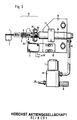
- Einzelheiten der Einrichtung zur Seitenpositionierung der Druckplatte werden im folgenden anhand von Fig. 2 näher beschrieben.
- Die auf den Belichtungssaugtisch 2 aufgelegte und mit Hilfe von nicht gezeigten Transportrollen in eine positionsnahe Lage beförderte Druckplatte 1 wird durch den Bolzen 6 des Druckstückes 10 an die zwei in Fig. 1 dargestellten Anschlagstifte 4 und 4' an der Gegenseite geschoben. Das Druckstück 10 besteht aus dem zylindrischen hohlen Bolzen 6 und einem Ring 20 und ist auf einer Kolbenstange 19 eines Hubzylinders 15 gelagert. Die Befestigung des Druckstückes 10 auf der Kolbenstange 19 erfolgt durch einen Stift 7, der in einem Schlitz 8 geführt ist. Eine Druckfeder 9 im Inneren des Bolzens 6 hält das Druckstück 10 in Ruhelage gegen den Stift 7 gedrückt.
- Der Hubzylinder 15 ist in einer Halterung 17 einstellbar, die auf einer Montageplatte 16 befestigt ist. Je nach der Breite der zu verarbeitenden Druckplatten wird der Hubzylinder 15 in der Halterung 17 verschoben. Der Hubzylinder 15 ist über ein Magnetventil 13 mit einer Druckleitung verbunden, die bei erregtem Magnetventil den Hubzylinder 15 mit Druckluft 18 beaufschlägt. Die in den Hubzylinder 15 einströmende Druckluft fährt die Kolbenstange 19 auf die volle Hublänge aus. Beim Ausfahren wird das Druckstück 10 mitgenommen und die Vorderkante des Bolzens trifft auf die Längskante der Druckplatte 1 auf. Die Druckplatte wird nun bis zu den gegenüberliegenden festen Anschlagstiften 4,4' seitlich verschoben. Innerhalb des Druckstückes 10 fährt die Kolbenstange 19 auf die volle Hublänge weiter und drückt die Druckfeder 9 zusammen, wobei der Stift 7 in dem Schlitz 8 in Richtung Druckplatte verfahren wird. Die Druckplatte wird lediglich von der Feder 9 über den Bolzen 6 des Druckstückes 10 gegen die beiden festen Anschlagstifte 4,4' gedrückt, wobei die Feder 9 die auf die volle Hublänge ausgefahrene Kolbenstange 19 soweit abfedert, daß die Anlage des Bolzens 6 an die Längskante der Druckplatte 1 elastisch und nicht starr erfolgt. Dadurch ist sichergestellt, daß durch die auf die volle Hublänge ausgefahrene Kolbenstange 19 die Druckplattenkante nicht beschädigt wird.
- Das Magnetventil 13 ist mit einem Drosselschalldämpfer 14 ausgerüstet, durch den bei entregtem Magnetventil 13 die Druckluft 18 ohne große Geräuschentwicklung austreten kann und über den die Kolbenbewegung regelbar ist. Sobald das Magnetventil 3u entregt wird, wird der Unterdruck auf den Belichtungssaugtisch 2 aufgehoben, so daß die Druckplatte 1 von dem Belichtungssaugtisch 2 abtransportiert werden kann.
- Die Längspositionierung, die noch nachstehend anhand der Fig. 2 und 3 beschrieben werden wird, beginnt gleichzeitig mit der Seitenpositionierung.
- Auf der Montageplatte 16 ist eine justierbare Einstellschiene 12 montiert, auf der ein Mikroschalter 11 angebracht ist, dessen Schaltfahne 35 in die Bewegungsbahn des Ringes 20 hineinragt.
- Sobald das Druckstück 10 die in Fig. 2 fest eingezeichnete Position verlassen hat und die gestrichelte Position in Fig. 2 einnimmt, in welcher der Bolzen 6 an der Längskante der Druckplatte 1 anliegt, betätigt der Ring 20 die Schaltfahne 35 des Mikroschalters 11. Der Mikroschalter 11 erregt ein weiteres Magnetventil 36, das in Fig. 3 gezeigt ist. Sobald das Magnetventil 36 erregt ist, wird ein Vakuumsaugkopf 37, der mit dem Belichtungssaugtisch 2 verbunden ist, mit Druckluft 22 beaufschlagt. Im Vakuumsaugkopf 37 entsteht dabei Unterdruck bzw. Saugluft, wodurch die Druckplatte 1 an die Oberfläche des Belichtungssaugtisches 2 angesaugt wird.
- Sobald die Druckplatte 1 angesaugt ist, schaltet ein nicht dargestellter Vakuumschalter bei fortbestehendem Vakuum das Magnetventil 13 aus, so daß die Druckluft 18 durch den Drosselschalldämpfer 14 des Magnetventils 13 austreten kann. Somit ist der Hubzylinder 15 nicht länger mit Druckluft beaufschlagt, so daß eine nicht gezeigte Rückholfeder im Hubzylinder die Kolbenstange 19 und mit ihr das Druckstück 10 in die Ausgangslage zurückziehen kann. Es liegt sodann die Druckplatte 1 angesaugt und zur Belichtung fertig positioniert auf dem Belichtungssaugtisch 2.
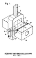
- Anhand von Fig. 3 wird im folgenden die Einrichtung zur Längspositionierung der Druckplatte 1 näher beschrieben. Der Schieber 5 ist in der Langlochführung 33 des Belichtungssaugtisches 2 geführt und um einen Bolzen 34 auf einem Druckstück 28 schwenkbar gelagert. Die Druckplatte 1 läuft beim Transport auf dem Belichtungssaugtisch 2 über den in Schräglage gekippten Schieber 5 der Einrichtung für die Längspositionierung.
- Auf der Unterseite des Belichtungssaugtisches 2 ist eine Lagerung 24 angeordnet, in der ein Hubzylinder 23, der dem Hubzylinder 15 für die Seitenpositionierung gleicht, verstellbar ist. Auf der Kolbenstange 25 des Hubzylinders 23 sitzt das Druckstück 28 auf, in dessen Innerem sich eine Druckfeder 29 befindet. Gleichzeitig mit der Seitenpositionierung wird ein Magnetventil 21 erregt und die Kolbenstange 25 mittels Druckluft 22 nach rechts gedrückt.
- Auf der Unterseite des Belichtungssaugtisches 2 ist ein Anschlagblech 26 angeordnet, das in die Langlochführung 33 des Belichtungssaugtisches 2 hineinragt. Das Anschlagblech 26 ist gewinkelt und beim Einfahren der Kolbenstange 25 des Hubzylinders 23, d.h. beim Verfahren in Fig. 3 nach links, wird der Schieber 5 gegen das Anschlagblech 26 gedrückt und um den Bolzen 34 schräg nach unten geschwenkt. Die Stirnfläche des Schiebers 5 ist abgeschrägt und liegt im geschwenkten Zustand des Schiebers 1 bis 2 mm unterhalb der Oberfläche des Belichtungssaugtisches 2.
- Bei einer Bewegung der Kolbenstange 25 nach rechts wird der Schieber 5 von dem Anschlagblech 26 gelöst und von einer Schenkelfeder 27 aufgerichtet, die auf dem Druckstück 28 angeordnet ist. Der Schieber 5 drückt dann die Druckplatte 1 mit ihrer Vorderkante gegen den in Fig. 1 dargestellten Anschlag 3. Sobald die Druckplatte 1 den Anschlag 3 trifft, übt sie einen leichten gleichmäßigen Druck auf den Schieber 5 aus, der in seiner Lage stehenbleibt. Die noch um einige Millimeter weiterfahrende Kolbenstange 25 drückt die im Druckstück 28 befindliche Druckfeder 29 zusammen.
- Die Kolbenstange 25 ist mit einem Bolzen 30 ausgerüstet, der in einem Langloch 31 des Druckstückes 28 geführt ist. Mit der Stirnfläche liegt die Kolbenstange 25 gegen die Druckfeder 29 an, die somit die mit voller Kraft auf ihre Endlänge ausfahrende Kolbenstange 25 abfedert. Dadurch wird die zwischen dem Anschlag 3 und dem Schieber 5 positionierte Druckplatte 1 durch die Druckfeder 29 gegen eine Beschädigung durch die Kolbenstange 25 geschützt. Das Ansaugen der Druckplatte 1 in dieser Lage wird durch die Seitenpositionierung ausgelöst, wie dies voranstehend anhand von Fig. 2 beschrieben wurde.
- In der Luftzuleitung oder -ableitung des Magnetventils 21 ist eine Luftdrossel 32 angeordnet, über welche die Geschwindigkeit der Kolbenstangenbewegung regelbar ist. An das Magnetventil 21 ist ein Drosselschalldämpfer 14 angeschlossen, durch den bei entregtem Magnetventil 21 Druckluft 22 regelbar austritt. Das Magnetventil 21 wird entregt, sobald das entsprechende Vakuum im Belichtungssaugtisch erreicht ist. Eine im -Hubzylinder 23 befindliche, nicht dargestellte Druckfeder drückt die Kolbenstange 25 in den Hubzylinder zurück. Wie schon zuvor erwähnt wurde, gleitet der Schieber 5 in der Langlochführung 33 nach links, bis er von dem Anschlagblech 26 in die Schräglage gedrückt wird. Nach der Belichtung der Druckplatte kann eine neue Druckplatte über den Schieber 5 transportiert und neu positioniert werden.
- Zur Erzeugung eines Unterdrucks im Belichtungssaugtisch 2 ist dieser über den Vakuumsaugkopf 37 mit dem Magnetventil 36 verbunden, das im erregten Zustand mit Druckluft 22 beaufschlagt wird. Mit dem Vakuumsaugkopf 37 steht ein Schalldämpfer 38 in Verbindung, über den Druckluft 22 auströmt, die im Betrieb des Vakuumsaugkopfes, der nach dem Prinzip eines Venturirohrs arbeitet, Unterdruck erzeugt.
- Fig. 4 zeigt eine perspektivische Ansicht des Druckstücks 28 und des Schiebers 5. Die dreiteilige Schenkelfeder 27 greift mit dem einen Schenkel 27' in eine Rille 39 auf der Oberseite des Druckstückes 28 ein. Die beiden anderen Schenkel 27" und 27"' der Schenkelfeder 27 umfassen Schenkel 40 eines Gabelstücks 41, wobei die Enden dieser beiden Schenkel in Nuten nahe den Schenkelenden eingreifen. Der Schenkel 27' einerseits und die beiden Schenkel 27" und 27"' andererseits streben unter dem Einfluß ihrer Federspannung im unbelasteten Zustand voneinander weg. Das Gabelstück 41 umschließt mit Spiel gegenüber der Oberfläche des Druckstückes 28 dessen schmaleren Abschnitt und wird von dem Bolzen 34 durchsetzt.
Claims (19)
Applications Claiming Priority (2)
| Application Number | Priority Date | Filing Date | Title |
|---|---|---|---|
| DE19823220861 DE3220861A1 (de) | 1982-06-03 | 1982-06-03 | Positionierungsvorrichtung |
| DE3220861 | 1982-06-03 |
Publications (3)
| Publication Number | Publication Date |
|---|---|
| EP0096294A2 true EP0096294A2 (de) | 1983-12-21 |
| EP0096294A3 EP0096294A3 (en) | 1986-01-22 |
| EP0096294B1 EP0096294B1 (de) | 1989-03-15 |
Family
ID=6165170
Family Applications (1)
| Application Number | Title | Priority Date | Filing Date |
|---|---|---|---|
| EP83105150A Expired EP0096294B1 (de) | 1982-06-03 | 1983-05-25 | Positionierungsvorrichtung |
Country Status (4)
| Country | Link |
|---|---|
| US (1) | US4533239A (de) |
| EP (1) | EP0096294B1 (de) |
| JP (1) | JPS58219555A (de) |
| DE (2) | DE3220861A1 (de) |
Cited By (2)
| Publication number | Priority date | Publication date | Assignee | Title |
|---|---|---|---|---|
| DE4205595A1 (de) * | 1991-02-22 | 1992-12-03 | Gerber Scientific Instr Co | Transportsystem fuer einen fotoplotter |
| EP0741317A1 (de) * | 1995-05-04 | 1996-11-06 | Xerox Corporation | Ausrichtstift |
Families Citing this family (9)
| Publication number | Priority date | Publication date | Assignee | Title |
|---|---|---|---|---|
| DE3335928A1 (de) * | 1983-10-04 | 1985-04-18 | L. Schuler GmbH, 7320 Göppingen | Einrichtung zum zufuehren von blechzuschnitten zur ziehstufe einer mehrstufenpresse |
| US5048816A (en) * | 1990-07-09 | 1991-09-17 | Murata Wiedemann, Inc. | Workpiece registration system and method for determining the position of a sheet |
| JP2669569B2 (ja) * | 1991-02-26 | 1997-10-29 | 富士写真フイルム株式会社 | 感光材料焼付装置及び位置合わせ装置 |
| JP3266304B2 (ja) * | 1991-07-16 | 2002-03-18 | 富士写真フイルム株式会社 | 感光材料焼付装置 |
| US5277507A (en) * | 1992-04-08 | 1994-01-11 | Stuart F. Cooper, Co. | Sheet feeder for engraving press |
| EP1085382B1 (de) * | 1999-09-17 | 2006-06-14 | Fuji Photo Film Co., Ltd. | Positionierungsverfahren und Positionierungsvorrichtung |
| EP1529746A3 (de) * | 2001-09-26 | 2005-06-29 | Fuji Photo Film Co., Ltd. | Vorrichtung zur Positionierung eines Bogens und Bildaufzeichnungsvorrichtung |
| US6772688B2 (en) * | 2002-04-05 | 2004-08-10 | Agfa Corporation | Imaging system with automated plate locating mechanism and method for loading printing plate |
| AT503790B1 (de) * | 2006-07-25 | 2008-01-15 | Trumpf Maschinen Austria Gmbh | Anschlagvorrichtung für eine biegepresse |
Family Cites Families (4)
| Publication number | Priority date | Publication date | Assignee | Title |
|---|---|---|---|---|
| US2565054A (en) * | 1946-10-19 | 1951-08-21 | Howard J Watrous | Automatic sheet registering device for lithographic and printing presses |
| DE3012761A1 (de) * | 1980-04-02 | 1981-10-08 | Hoechst Ag, 6000 Frankfurt | Vorrichtung fuer den einzug und den transport von druckformen |
| JPS5778541A (en) * | 1980-11-04 | 1982-05-17 | Fuji Photo Film Co Ltd | Positioning device conveyance of ps plate |
| DE3122321A1 (de) * | 1981-06-05 | 1982-12-23 | Hoechst Ag, 6000 Frankfurt | Einzugs- und transportvorrichtung fuer druckformen |
-
1982
- 1982-06-03 DE DE19823220861 patent/DE3220861A1/de not_active Withdrawn
-
1983
- 1983-05-25 EP EP83105150A patent/EP0096294B1/de not_active Expired
- 1983-05-25 DE DE8383105150T patent/DE3379427D1/de not_active Expired
- 1983-05-30 JP JP58094217A patent/JPS58219555A/ja active Granted
- 1983-05-31 US US06/499,466 patent/US4533239A/en not_active Expired - Fee Related
Cited By (3)
| Publication number | Priority date | Publication date | Assignee | Title |
|---|---|---|---|---|
| DE4205595A1 (de) * | 1991-02-22 | 1992-12-03 | Gerber Scientific Instr Co | Transportsystem fuer einen fotoplotter |
| DE4205595C2 (de) * | 1991-02-22 | 1998-02-19 | Gerber Systems Corp | Transportsystem und Verfahren zum Transport |
| EP0741317A1 (de) * | 1995-05-04 | 1996-11-06 | Xerox Corporation | Ausrichtstift |
Also Published As
| Publication number | Publication date |
|---|---|
| DE3379427D1 (en) | 1989-04-20 |
| DE3220861A1 (de) | 1984-02-02 |
| JPS58219555A (ja) | 1983-12-21 |
| EP0096294B1 (de) | 1989-03-15 |
| JPH0335656B2 (de) | 1991-05-29 |
| US4533239A (en) | 1985-08-06 |
| EP0096294A3 (en) | 1986-01-22 |
Similar Documents
| Publication | Publication Date | Title |
|---|---|---|
| DE2842116C2 (de) | ||
| DE69317051T2 (de) | Speicher für bögen mit zurückziehbarer rampe | |
| DE4214049C2 (de) | ||
| EP0096294B1 (de) | Positionierungsvorrichtung | |
| DE69106190T2 (de) | Vorrichtung zum Formen und Eintreiben von Heftklammern. | |
| DE3246849C2 (de) | ||
| DE1560349C3 (de) | Arbeitsverfahren und Einrichtung zum endengleichen Sortieren von Hülsen | |
| EP0066789B1 (de) | Einzugs- und Transportvorrichtung für Druckformen | |
| DE19511296C2 (de) | Vorrichtung zum Anheben und Abtransportieren flächiger Gegenstände | |
| EP0037065A2 (de) | Vorrichtung für den Einzug und den Transport von Druckformen | |
| EP0071171A1 (de) | Saugvorrichtung | |
| DE4332803C2 (de) | Vorrichtung zum automatischen Zuführen von Druckplatten zum Plattenzylinder einer Druckmaschine | |
| DE2537410C2 (de) | Vorrichtung zum Stapeln von Einzelblechen zu einem Blechpaket | |
| DE3317522C2 (de) | Einschubvorrichtung für eine Durchlauffugenverleimpresse | |
| AT391439B (de) | Verfahren und vorrichtung zum montieren eines elastischen ringes in einer ringnut eines zylindrischen koerpers | |
| CH667435A5 (de) | Verfahren und vorrichtung zum automatischen anbringen eines pfeiletiketts im mittelloch eines garnknaeuels. | |
| DE3009423C2 (de) | Verfahren und Vorrichtung zum vollautomatischen Stanzen von Druckplatten, insbesondere Offsetdruckplatten | |
| DE1761358A1 (de) | Vorrichtung an Druckmaschinen fuer das seitliche Ausrichten von Papierboegen | |
| DE1294475B (de) | Geraet zum streifenfoermigen Aufbringen einer Beschichtung fuer magnetische Aufzeichnung | |
| DE1255299B (de) | Vorrichtung zum Einsetzen von Gleitschutzstiften in vorbereitete Loecher des Laufbelages eines geheizten Fahrzeugreifens | |
| DE2543105C3 (de) | Vorrichtung zum Auftragen von Klebestreifen | |
| AT402206B (de) | Übergabevorrichtung zum einschieben von etiketten in den nähbereich einer nähmaschine | |
| DE2656116C3 (de) | Vorrichtung zum stapelweisen Ablegen von flexiblen Paneelen auf einem unterhalb eines Endlosförderers angeordneten Stapeltisch | |
| DE3105415A1 (de) | Vorrichtung fuer den transport von steifem plattenfoermigem druckgut | |
| DE345532C (de) |
Legal Events
| Date | Code | Title | Description |
|---|---|---|---|
| PUAI | Public reference made under article 153(3) epc to a published international application that has entered the european phase |
Free format text: ORIGINAL CODE: 0009012 |
|
| AK | Designated contracting states |
Designated state(s): BE DE FR GB IT NL |
|
| 17P | Request for examination filed |
Effective date: 19841206 |
|
| PUAL | Search report despatched |
Free format text: ORIGINAL CODE: 0009013 |
|
| AK | Designated contracting states |
Designated state(s): BE DE FR GB IT NL |
|
| 17Q | First examination report despatched |
Effective date: 19871027 |
|
| GRAA | (expected) grant |
Free format text: ORIGINAL CODE: 0009210 |
|
| AK | Designated contracting states |
Kind code of ref document: B1 Designated state(s): BE DE FR GB IT NL |
|
| REF | Corresponds to: |
Ref document number: 3379427 Country of ref document: DE Date of ref document: 19890420 |
|
| ET | Fr: translation filed | ||
| ITF | It: translation for a ep patent filed | ||
| GBT | Gb: translation of ep patent filed (gb section 77(6)(a)/1977) | ||
| PLBE | No opposition filed within time limit |
Free format text: ORIGINAL CODE: 0009261 |
|
| STAA | Information on the status of an ep patent application or granted ep patent |
Free format text: STATUS: NO OPPOSITION FILED WITHIN TIME LIMIT |
|
| 26N | No opposition filed | ||
| ITTA | It: last paid annual fee | ||
| PGFP | Annual fee paid to national office [announced via postgrant information from national office to epo] |
Ref country code: FR Payment date: 19920410 Year of fee payment: 10 |
|
| PGFP | Annual fee paid to national office [announced via postgrant information from national office to epo] |
Ref country code: BE Payment date: 19920504 Year of fee payment: 10 |
|
| PG25 | Lapsed in a contracting state [announced via postgrant information from national office to epo] |
Ref country code: BE Effective date: 19930531 |
|
| BERE | Be: lapsed |
Owner name: HOECHST A.G. Effective date: 19930531 |
|
| PG25 | Lapsed in a contracting state [announced via postgrant information from national office to epo] |
Ref country code: FR Effective date: 19940131 |
|
| REG | Reference to a national code |
Ref country code: FR Ref legal event code: ST |
|
| PGFP | Annual fee paid to national office [announced via postgrant information from national office to epo] |
Ref country code: GB Payment date: 19940428 Year of fee payment: 12 |
|
| PGFP | Annual fee paid to national office [announced via postgrant information from national office to epo] |
Ref country code: NL Payment date: 19940531 Year of fee payment: 12 |
|
| PGFP | Annual fee paid to national office [announced via postgrant information from national office to epo] |
Ref country code: DE Payment date: 19940714 Year of fee payment: 12 |
|
| PG25 | Lapsed in a contracting state [announced via postgrant information from national office to epo] |
Ref country code: GB Effective date: 19950525 |
|
| PG25 | Lapsed in a contracting state [announced via postgrant information from national office to epo] |
Ref country code: NL Effective date: 19951201 |
|
| GBPC | Gb: european patent ceased through non-payment of renewal fee |
Effective date: 19950525 |
|
| NLV4 | Nl: lapsed or anulled due to non-payment of the annual fee |
Effective date: 19951201 |
|
| PG25 | Lapsed in a contracting state [announced via postgrant information from national office to epo] |
Ref country code: DE Effective date: 19960201 |