EP0096400A2 - Installation de fermeture pour la consolidation des portes - Google Patents
Installation de fermeture pour la consolidation des portes Download PDFInfo
- Publication number
- EP0096400A2 EP0096400A2 EP83105531A EP83105531A EP0096400A2 EP 0096400 A2 EP0096400 A2 EP 0096400A2 EP 83105531 A EP83105531 A EP 83105531A EP 83105531 A EP83105531 A EP 83105531A EP 0096400 A2 EP0096400 A2 EP 0096400A2
- Authority
- EP
- European Patent Office
- Prior art keywords
- locking bolt
- locking
- bolt
- lock system
- drive
- Prior art date
- Legal status (The legal status is an assumption and is not a legal conclusion. Google has not performed a legal analysis and makes no representation as to the accuracy of the status listed.)
- Granted
Links
- 238000009434 installation Methods 0.000 title description 5
- 230000011664 signaling Effects 0.000 claims description 9
- 239000011159 matrix material Substances 0.000 claims description 5
- 230000000903 blocking effect Effects 0.000 claims description 3
- 230000004913 activation Effects 0.000 claims 1
- 238000012544 monitoring process Methods 0.000 description 4
- 238000013475 authorization Methods 0.000 description 2
- 230000000284 resting effect Effects 0.000 description 2
- 235000010678 Paulownia tomentosa Nutrition 0.000 description 1
- 240000002834 Paulownia tomentosa Species 0.000 description 1
- 241000904937 Sirenes Species 0.000 description 1
- 238000006243 chemical reaction Methods 0.000 description 1
- 230000007547 defect Effects 0.000 description 1
- 238000001514 detection method Methods 0.000 description 1
- 238000010586 diagram Methods 0.000 description 1
- 238000006073 displacement reaction Methods 0.000 description 1
- 230000000694 effects Effects 0.000 description 1
- 238000010616 electrical installation Methods 0.000 description 1
- 230000002349 favourable effect Effects 0.000 description 1
- 238000012806 monitoring device Methods 0.000 description 1
- 238000009420 retrofitting Methods 0.000 description 1
- 230000001960 triggered effect Effects 0.000 description 1
Images

Classifications
-
- E—FIXED CONSTRUCTIONS
- E05—LOCKS; KEYS; WINDOW OR DOOR FITTINGS; SAFES
- E05B—LOCKS; ACCESSORIES THEREFOR; HANDCUFFS
- E05B45/00—Alarm locks
- E05B45/06—Electric alarm locks
- E05B45/08—Electric alarm locks with contact making inside the lock or in the striking plate
- E05B45/083—Electric alarm locks with contact making inside the lock or in the striking plate with contact making either in the striking plate or by movement of the bolt relative to the striking plate
-
- E—FIXED CONSTRUCTIONS
- E05—LOCKS; KEYS; WINDOW OR DOOR FITTINGS; SAFES
- E05B—LOCKS; ACCESSORIES THEREFOR; HANDCUFFS
- E05B47/00—Operating or controlling locks or other fastening devices by electric or magnetic means
- E05B47/06—Controlling mechanically-operated bolts by electro-magnetically-operated detents
- E05B47/0696—Controlling mechanically-operated bolts by electro-magnetically-operated detents locking the bolt by an electromagnet in the striker
-
- Y—GENERAL TAGGING OF NEW TECHNOLOGICAL DEVELOPMENTS; GENERAL TAGGING OF CROSS-SECTIONAL TECHNOLOGIES SPANNING OVER SEVERAL SECTIONS OF THE IPC; TECHNICAL SUBJECTS COVERED BY FORMER USPC CROSS-REFERENCE ART COLLECTIONS [XRACs] AND DIGESTS
- Y10—TECHNICAL SUBJECTS COVERED BY FORMER USPC
- Y10S—TECHNICAL SUBJECTS COVERED BY FORMER USPC CROSS-REFERENCE ART COLLECTIONS [XRACs] AND DIGESTS
- Y10S70/00—Locks
- Y10S70/49—Locks with alarm
-
- Y—GENERAL TAGGING OF NEW TECHNOLOGICAL DEVELOPMENTS; GENERAL TAGGING OF CROSS-SECTIONAL TECHNOLOGIES SPANNING OVER SEVERAL SECTIONS OF THE IPC; TECHNICAL SUBJECTS COVERED BY FORMER USPC CROSS-REFERENCE ART COLLECTIONS [XRACs] AND DIGESTS
- Y10—TECHNICAL SUBJECTS COVERED BY FORMER USPC
- Y10T—TECHNICAL SUBJECTS COVERED BY FORMER US CLASSIFICATION
- Y10T70/00—Locks
- Y10T70/50—Special application
- Y10T70/5093—For closures
- Y10T70/5155—Door
- Y10T70/5199—Swinging door
- Y10T70/5246—Dead bolts
- Y10T70/5248—Multiple
- Y10T70/527—Sliding
-
- Y—GENERAL TAGGING OF NEW TECHNOLOGICAL DEVELOPMENTS; GENERAL TAGGING OF CROSS-SECTIONAL TECHNOLOGIES SPANNING OVER SEVERAL SECTIONS OF THE IPC; TECHNICAL SUBJECTS COVERED BY FORMER USPC CROSS-REFERENCE ART COLLECTIONS [XRACs] AND DIGESTS
- Y10—TECHNICAL SUBJECTS COVERED BY FORMER USPC
- Y10T—TECHNICAL SUBJECTS COVERED BY FORMER US CLASSIFICATION
- Y10T70/00—Locks
- Y10T70/70—Operating mechanism
- Y10T70/7051—Using a powered device [e.g., motor]
- Y10T70/7062—Electrical type [e.g., solenoid]
Definitions
- the invention relates to a lock system for securing doors or the like. With two bolts which are mounted so as to be movable relative to the door to be locked and two locking devices assigned to them, one of the two locking devices has a locking mechanism which can be locked with a key, and the other is assigned a unlockable unlocking drive .
- Lock systems are already known which, in order to secure doors, in particular in small safe systems, have two latches which are mounted so as to be movable relative to the door to be locked, and locking devices assigned to them.
- One of the two bolts can be unlocked manually using a locking mechanism that can be locked with a key.
- the other bolt can be released fully automatically via a remote-controlled unlocking drive.
- a relatively large amount of force is required to adjust this externally actuable bolt.
- Each lock is therefore equipped with control lines for the lock monitoring and also with constant current lines for actuating the drive device for the remotely operable locking bolt.
- the present invention has for its object to provide a lock system of the type described above, in which the actuatable opening of the locking bolt requires little power, so that the electrical installation of such lock systems is simplified.
- the use of Standard locks are made possible.
- This object of the invention is achieved in that a position sensor is assigned to the locking bolt which can be locked with the locking mechanism, which is activated when the locking bolt is open and releases the action on the remotely operable unlocking drive and that the locking bolt assigned to the unlocking drive is assigned a drive device which is effective in the opening direction and which interacts with the locking bolt and is adjustable with it into a starting position provided for adjusting the locking bolt.
- the advantage of this surprisingly simple solution is that the force applied when the manually operated locking bolt is actuated is stored in order to adjust the securing bolt. Characterized in that the manually applied adjusting force for the locking bolt is used for the adjustment of the locking bolt in the open or closed position, the power requirement that is to be applied by the electrical energy is low.
- the securing bolt is displaceably mounted in a guideway running in the opening direction, in particular arranged on the locking bolt, and that the locking device assigned to the securing bolt is moved by a Unlocking drive formed electromagnet and has a locking lever engaging in the locking bolt, which is adjustable by the electromagnet in a release position removed from the locking bolt.
- the drive device for the security bolt by a pulling device arranged between the locking and security bolt, e.g. a coil spring is formed. It is advantageous in this embodiment that the force required to open the locking bolt can also be applied after the locking bolt has been actuated or opened. By prestressing the pulling device or the helical spring forming it, the force for displacing the securing bolt is available even after actuation of the locking bolt when the locking lever is released.
- the guideway for the securing bolt is preferably arranged in the door frame and that the drive device is formed by a tension device arranged between the securing bolt and the door frame.
- An embodiment of the invention is advantageous in which the The locking bolt is rotatably mounted about an axis and the drive device has a pulling device, for example a helical spring, which, due to the unlocking drive, for example an electromagnet, moves from a rest position between the axis and one end face of the locking bolt to a position between the axis and the opposite end face of the locking bolt located opening position can be brought.
- a pulling device for example a helical spring
- the locking bar, the associated drive device and the unlocking drive and the position transmitter assigned to the locking bar are arranged in the door frame.
- an embodiment is also possible according to which the position transmitter is parallel to the unlocking drive, e.g. the electromagnet, is switched and an interrupter element e.g. has an opening contact that is activated when the locking bolt is open.
- This embodiment is characterized by an extremely low installation effort, since only two lines are required to monitor the position of the position transmitter and to act on the unlocking drive. It is also advantageous if the position transmitter and the unlocking drive are connected to both a high-frequency supply system and a low-frequency supply system, since different information can be conveyed in a simple manner via the same line system. So both the position of the position transmitter and the actuation of an electromagnet can be carried out without mutual interference.
- the control device for the lock system has a row-column matrix and the position transmitters are connected to the high-frequency supply system via a row control unit and a column control unit, and that a code element is activated when the opening contact of the position transmitter is activated is activated, which connects the unlocking drive to the low-frequency supply system via the row control unit and the column control unit, preferably a blocking element being assigned to the code element, which is interconnected on a coding unit and an alarm signaling system and, when the position transmitter is activated, the alarm signaling system is not present without a release signal from the coding unit is activated.
- control and surveil - monitoring device can be used in conjunction with the row-column matrix with a very low installation costs in a variety of inventive lock systems, for example in small vault systems, the Aus GmbH be found. It is advantageous that the existing components can also be used for monitoring against unauthorized opening of the doors secured by the lock systems according to the invention. In this way, a favorable combination of effort in the lock system and achievable level of security is achieved.
- the safety bolt or its drive device is assigned an emergency opening device which preferably comprises an actuating device which can be brought into engagement with the safety bolt or its drive device via a lock. This makes it possible to actuate the locking bolt by manual intervention in connection with another key even after the drive device or the unlocking drive has failed.
- a lock system 4 is arranged between the door 2 and the door frame 3.
- This lock system 4 comprises a locking bolt 5 and a locking bolt 6.
- the locking bolt 5 is assigned a locking device 7 and the locking bolt 6 is a locking device 8.
- the locking device 7 comprises a manually operated locking mechanism 9 which has a handle 11 which can be locked with a key 10.
- a drive device 12 is arranged between the locking bar 5 and the locking bar 6, which e.g. is formed by a coil spring 13.
- An unlocking drive 14, namely an electromagnet 15, is shown in the door frame 3 by the locking device 8 for the locking bolt 6.
- the locking bolt 5 is assigned a position transmitter in the door frame 3.
- the electromagnet 15 and the position transmitter 16 are connected to a control device 19 via two lines 17, 18.
- This control device 19 is equipped with a high-frequency supply system 20, a low-frequency supply system 21, a row control unit 22, a column control unit 23, a program switch 24, e.g. a computer, an energy supply device 25, an alarm signaling system 26 and a siren 27 assigned to this alarm signaling system.
- the lock system 1 is shown, the locking bolt 5 is open. This is done in that the handle 11 is released by turning the key 10 by 90 degrees and by turning the handle 11, the bolt 5 is moved from the rest position 28 shown in broken lines to the open position 29 shown in full lines.
- the locking bolt 6 is in the closed position because it is held in place by a locking lever 30, which is connected to the unlocking drive 14. Due to the movement of the locking bolt 5 into the open position 29, the drive device 12 - the helical spring 13 - is pretensioned so that after the locking bolt 6 has been released, it is arranged along one on the locking bolt 5 Guide track 31 in the opening direction - arrow 32 - in the open position drawn with dashed lines.
- the position transmitter 16 is also released and an interrupter member 33 is opened.
- FIG 3 the storage of the locking lever 30 is shown.
- the locking lever 30 is rotatably mounted on an axis 34 - approximately in its longitudinal center - which is held in the door frame 3, and coupled in its end region facing away from the locking bolt 6 to the electromagnet 15 of the locking drive 14.
- the locking lever 30 In its position fixing the locking bolt 6, the locking lever 30 is biased in the direction of the locking bolt 6 with a tension spring 35.
- the lever with the electromagnet 15 is pivoted up against the tension spring 35.
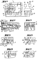
- FIGS. 4-7 then show the different positions of the securing and locking bolt 6, 7 of the drive device 12 between the two bolts and the position transmitter 16 and the locking lever 30.
- the lock system is shown in the locked state.
- the locking mechanism 9 is closed and locked with the key.
- the position transmitter 16 is actuated by the locking bolt 5.
- the interrupter member 33 is closed.
- the high frequency fed into the lines 17 and 18 by the control device 19 does not influence the coil of the electromagnet 15, but can be passed back to the control device unhindered via the closed contact of the interrupter member 33.
- the position transmitter 16 is released when the locking bolt 5 is opened and the interrupter member 33 is opened.
- the locking mechanism 9 can be unlocked with the key and the locking bolt 5 can be moved into its open position by turning the handle 11, as shown in FIG. 5. This displacement of the locking bolt 5 prestresses the drive device 12, namely the coil spring 13, since the locking bolt 6 is still blocked with the locking lever 30.
- the opening of the interrupter member 33 now shows the control device 19 that the locking bolt 5 in the door 2 is open, so that the bypass line of the electromagnet 15 is interrupted and a low-frequency voltage can now be supplied by the control device 19 via the same lines 17, 18 that excites the electromagnet 15 briefly.
- the force of the electromagnet 15 only has to be sufficient to overcome the effect of the tension spring 35 and to bring the locking lever 30 out of the cross-sectional area of the locking bolt 6.
- the force required to move the locking bolt 6 into its open position after the locking lever 30 has been raised is applied by the pre-tensioned coil spring 13.
- only an electromagnet with low power is required, and small line cross sections are sufficient to act on the electromagnet 15.
- FIG. 6 shows the position of the locking and securing bolt 5 or 6 in which the door 2 can be opened.
- FIG. 7 shows that when the lock system is closed by means of the handle 11, the locking and securing bolts 5 and 6 are simultaneously moved in the direction of the door frame 3.
- the interrupter member 33 is closed by the locking bolt 5.
- the shape of the end face of the locking bolt 6 ensures that when the locking lever 30 is closed it is pushed up against the action of the tension spring 35 and engages in the locking bolt 6. The state, as already shown in FIG. 4, is thus restored.
- FIGS. 8 and 9 show an embodiment variant of a lock system 1 shown.
- a locking bolt 36 is arranged in the door frame 3 of a small safe.
- a locking bolt 37 is arranged in the door 2.
- a position transmitter 16 is assigned to the locking bolt 37 in the door frame 3.
- An opening contact 38 of this position transmitter 16, which is designed as an interrupter member 33, is open since the locking bolt 37 has already been opened and drawn into the door 2.
- the door 2 is still blocked against opening by the locking bolt 36.
- an unlocking drive 39 is arranged, which comprises an electromagnet 15 and a pulling device 41, which is formed by a helical spring 40 and serves as a drive device for the locking bolt 36.
- This coil spring 40 is mounted with its end 42 in the door frame 3 and with its end 43 on the locking bolt 36. In the closed position of the locking bolt 36, there is a helical spring 40 between an axis 44, about which the locking bolt 36 can be pivoted, and an end face 45 thereof. A push rod 46 of the electromagnet 15 is guided in a link path 47 which is central to the axis 44. If the safety latch 36 is opened, the electromagnet 15 is acted upon via the lines 17, 18 and pulls the push rod 46. The locking bolt 36 is pivoted into its open position 48, drawn with dashed lines, in the direction of the arrow 49.
- the force of the electromagnet 15 can be kept low, since even after a small pivoting angle, the end 43 of the pulling device 41 is located between the axis 44 and an end face 50, which is close to the slide track 47, and supports the opening movement of the securing bolt 36.
- the securing bolt 36 has a driving pin 51 which, when the securing bolt 36 is opened, is pivoted into the path of movement of the locking bolt 37, as indicated by broken lines. Due to the manual force applied when the locking bolt 37 is closed, the locking bolt 36 is moved via the driving pin 51 into the rest position 52 drawn with solid lines and the coil spring 40 is biased again for a further opening movement.
- FIGS. 10-14 show the different positions of the locking and securing bolts 36, 37 and of the position transmitter 16 for a better understanding of the mode of operation of the lock system according to the invention.
- FIG. 14 it is shown how the locking bar 37 is moved back into its closed position shown in FIG. 10 by the manual movement of the locking bolt 37 when the lock system 1 is locked against the opening direction - arrow 54 - via the driving pin 51.
- FIG. 15 shows the control device 19 associated with the lock systems.
- a so-called row-column matrix is activated for controlling the position transmitter 16 in the individual doors.
- a high-frequency current pulse or a pulse packet is output which does not attract the electromagnet 15.
- the query impulse can be issued per lock system or together for an entire column.
- the control device 19 is provided with a row drive unit 22 and a column drive unit 23.
- the individual rows and columns of the control system can be interconnected with a high-frequency supply system 20 or a low-frequency supply system 21 via the row and column control unit 22, 23.
- the row or column control units 22, 23 are controlled by a program switching device 24 or are connected to a power supply unit 25.
- the program switching mechanism is assigned an alarm system 26 with a siren 27.
- this alarm signaling system 26 can be connected to any alarm signaling device, for example a light signal system or a fully automatic intrusion detection system with a report to the police.
- the function of the control device 19 is such that a common query pulse is triggered by the program switching mechanism 24 per lock or for the locks arranged in a column, for example along the line 17. This is done in such a way that individual current pulses or high-frequency current pulse packets are supplied from the high-frequency supply system 20 to the individual lock systems 1 via the column control unit 23. This high-frequency current pulse goes through the electrical system magnet 15 does not go through. It also doesn't attract the magnet. If the interrupter member 33 of the position transmitter 16 is closed, these impulses are fed back unhindered to the control device 19 via the interrupter member. A continuous passage of this pulse or this pulse packet can be seen in the program switching mechanism 24. The condition is recognized as properly closed.
- the opening of the door 2 is stored via the program switching mechanism 24.
- the opening contact 38 of the position transmitter 16 is opened.
- the interruption of the forwarding of the high-frequency current pulses or pulse packets signals the program switching mechanism 24 that the locking bolt 6 assigned to the lock system is to be opened.
- the program switching device 24 switches the low-frequency supply system 21 to the lines 17 and 18 due to the change in the position of the position transmitter 16. Since the opening contact 38 of the position transmitter 16 is open, the electromagnet 15 picks up and opens the locking lever 30. The locking latch 6 is pulled into its open position .
- the closed state of the lock system 1 is recognized again by the program switching mechanism 24 and the lock system is again subjected to normal monitoring by means of the high-frequency current pulses.
- the program switching mechanism can be programmed in such a way that a warning signal is emitted after a certain period of opening, in order to prevent doors of a safe system from being accidentally left open.
- an opening of the locking bar 6 can be provided, as schematically indicated in FIG. 9, an emergency opening device 59 can be provided.
- this comprises a lock 60 and an actuating device 61. If necessary, the actuating device is unlocked with the key 60 via the lock 60 and pressed in the direction of the locking bolt 36 until the actuating device 61 provided with an internal square on the, on the securing bolt 36, in Area of the axis 44 applied square 62 includes. The locking bolt 36 can then be pivoted into the open position by rotating the actuating device 61.
Landscapes
- Physics & Mathematics (AREA)
- Electromagnetism (AREA)
- Lock And Its Accessories (AREA)
- Control Of Vending Devices And Auxiliary Devices For Vending Devices (AREA)
- Vehicle Step Arrangements And Article Storage (AREA)
Applications Claiming Priority (2)
| Application Number | Priority Date | Filing Date | Title |
|---|---|---|---|
| AT2208/82 | 1982-06-07 | ||
| AT0220882A AT381131B (de) | 1982-06-07 | 1982-06-07 | Schlossanlage zur sicherung von tueren |
Publications (3)
| Publication Number | Publication Date |
|---|---|
| EP0096400A2 true EP0096400A2 (fr) | 1983-12-21 |
| EP0096400A3 EP0096400A3 (en) | 1984-03-21 |
| EP0096400B1 EP0096400B1 (fr) | 1986-04-09 |
Family
ID=3530021
Family Applications (1)
| Application Number | Title | Priority Date | Filing Date |
|---|---|---|---|
| EP83105531A Expired EP0096400B1 (fr) | 1982-06-07 | 1983-06-06 | Installation de fermeture pour la consolidation des portes |
Country Status (5)
| Country | Link |
|---|---|
| US (1) | US4563886A (fr) |
| EP (1) | EP0096400B1 (fr) |
| AT (2) | AT381131B (fr) |
| BR (1) | BR8302972A (fr) |
| DE (1) | DE3362899D1 (fr) |
Cited By (12)
| Publication number | Priority date | Publication date | Assignee | Title |
|---|---|---|---|---|
| WO1989011016A1 (fr) * | 1988-05-06 | 1989-11-16 | Keba Gesellschaft M.B.H. & Co. | Agencement de coffres multiples |
| EP0450399A3 (en) * | 1990-03-22 | 1991-12-27 | Keba Gesellschaft M.B.H. & Co. | Safe, especially safe deposit box with electric remote control |
| CH679603A5 (en) * | 1989-05-29 | 1992-03-13 | Vidmar Ag | Bank safe installation security compartment - has second door hinged on first one outside, covering its lock when shut |
| DE4302835C1 (de) * | 1993-01-27 | 1994-06-09 | Krone Ag | Schließeinrichtung für die Tür eines Gehäuses |
| EP0697490A1 (fr) * | 1994-07-18 | 1996-02-21 | Fritz Fuss GmbH & Co. | Dispositif d'actionnement d'un pêne commandé |
| DE19537811C1 (de) * | 1995-10-11 | 1996-11-28 | Garny Sicherheitstechn Gmbh | Bank-Mietfachanlage mit elektronischer Steuerung |
| EP0811738A1 (fr) * | 1996-06-06 | 1997-12-10 | PHF-Création Sàrl | Dispositif de verrouillage |
| WO1999018311A1 (fr) * | 1997-10-02 | 1999-04-15 | Rolf Maniago | Dispositif de fermeture pour une serrure |
| US6076384A (en) * | 1998-02-27 | 2000-06-20 | Rittal-Werk Rudolf Loh Gmbh & Co. Kg | Closure for a switchgear cabinet door, machine case or the like |
| US6363762B1 (en) * | 1996-12-24 | 2002-04-02 | Kaba Schliessysteme Ag | Locking device |
| US6374651B1 (en) * | 1998-02-27 | 2002-04-23 | Rittal-Werk Rudolf Loh Gmbh & Co. Kg | Closing device for a control cabinet door, machine casing or such like |
| DE102012022640A1 (de) | 2012-11-21 | 2014-05-22 | Contecon Software Gmbh | Schließfachanlage mit mehreren Schließfächern |
Families Citing this family (18)
| Publication number | Priority date | Publication date | Assignee | Title |
|---|---|---|---|---|
| DE3615173A1 (de) * | 1986-05-05 | 1987-11-12 | Fuss Fritz Gmbh & Co | Blockschloss |
| US4929003A (en) * | 1988-10-07 | 1990-05-29 | Adtec Incorporated | Motorized locking mechanism for a door |
| US5132667A (en) * | 1990-05-04 | 1992-07-21 | Cranford Barbara J | Cranford alert system - burglar alarm |
| US6283514B1 (en) | 1996-08-16 | 2001-09-04 | K. A. Schmersal Gmbh & Co. | Apparatus for monitoring and controlling access to a restricted area |
| US6032500A (en) * | 1997-04-18 | 2000-03-07 | Stephen C. Cohen | Kit for retrofitting a door with a security lock system |
| US5852944A (en) * | 1997-04-18 | 1998-12-29 | Stephen C. Cohen | Remotely controlled door lock |
| US6539760B1 (en) * | 1999-05-24 | 2003-04-01 | K.A. Schmersal Gmbh & Co. | Monitoring device |
| ES2166344B1 (es) * | 2000-09-26 | 2003-03-01 | Siemens Elasa S A | Hucha de seguridad para telefonos publicos. |
| JP2002354134A (ja) * | 2001-05-23 | 2002-12-06 | Aiphone Co Ltd | 集合住宅インターホンシステム |
| NL1021889C2 (nl) * | 2002-11-11 | 2004-05-12 | Coin Street B V | Beveiligde opslag. |
| CA2413836A1 (fr) * | 2002-12-11 | 2004-06-10 | Cliff Martin | Appareil electronique de verrouillage de porte |
| DE10305704B3 (de) * | 2003-02-12 | 2004-06-24 | K.A. Schmersal Gmbh & Co | Sicherheitszuhaltung |
| DE102008020789A1 (de) * | 2008-04-25 | 2009-11-05 | Airbus Deutschland Gmbh | Befestigungssystem sowie Verfahren zum Befestigen eines Elementes einer Flugzeuginnenausstattung |
| DE102008060004B4 (de) * | 2008-11-25 | 2021-09-02 | Pilz Gmbh & Co. Kg | Sicherheitsschalter zum Erzeugen eines Anlagenfreigabesignals in Abhängigkeit von der Position einer beweglichen Schutztür |
| DE102014006694B3 (de) * | 2014-05-09 | 2015-10-29 | Security Performance Hartmann Gmbh | Schließfachanlage mit einer Mehrzahl von Schließfächern |
| CN104213762A (zh) * | 2014-06-27 | 2014-12-17 | 冯政 | 电磁式堵锁器 |
| CN104481240A (zh) * | 2014-11-17 | 2015-04-01 | 徐浩钟 | 锁止机电互锁防盗报警锁 |
| US10584515B2 (en) | 2016-09-06 | 2020-03-10 | Ellenby Technologies, Inc. | Electronic lock for safes |
Family Cites Families (12)
| Publication number | Priority date | Publication date | Assignee | Title |
|---|---|---|---|---|
| DE475098C (de) * | 1929-08-09 | Emil Peters | Tuerschloss | |
| US2045186A (en) * | 1933-09-26 | 1936-06-23 | Honsel Fritz | Combined electrical and key operated lock |
| CH188572A (de) * | 1936-05-12 | 1937-01-15 | Hasler Ag | Als zusätzliches, elektrisches Sicherheitsschloss wirkende Abschliesseinrichtung an Türen. |
| US2188034A (en) * | 1937-03-13 | 1940-01-23 | Darby John Henry | Fastening for doors |
| US2786701A (en) * | 1953-09-22 | 1957-03-26 | Frederick C Povlich | Automobile door safety lock |
| US2989859A (en) * | 1958-08-29 | 1961-06-27 | Adams Rite Mfg Company | Narrow stile double bolt door lock |
| US3167942A (en) * | 1961-07-24 | 1965-02-02 | Warner W Clements | Remotely controllable lock set |
| DE1907145U (de) * | 1964-10-06 | 1964-12-23 | Ernst Hamann | Klosettbrillenauflage. |
| DE1678033A1 (de) * | 1967-11-14 | 1971-06-09 | Helmut Kiehne | Elektromechanisches Sperrschloss zur Gewaehrleistung der Zwanglaeufigkeit in der Bedienung von Notruf- und Sicherungsanlagen |
| DE2325566B2 (de) * | 1973-05-19 | 1981-06-04 | Zeiss Ikon Ag Goerz-Werk, 1000 Berlin | Magnetisch/mechanisch arbeitender Schließzylinder |
| US3872696A (en) * | 1973-10-15 | 1975-03-25 | Arthur V Geringer | Combination lock and fail-safe latch for exit doors |
| US4355830A (en) * | 1980-02-25 | 1982-10-26 | Cni Incorporated | Electrical locking mechanism |
-
1982
- 1982-06-07 AT AT0220882A patent/AT381131B/de not_active IP Right Cessation
-
1983
- 1983-05-26 US US06/498,309 patent/US4563886A/en not_active Expired - Lifetime
- 1983-06-06 AT AT83105531T patent/ATE19125T1/de not_active IP Right Cessation
- 1983-06-06 BR BR8302972A patent/BR8302972A/pt not_active IP Right Cessation
- 1983-06-06 DE DE8383105531T patent/DE3362899D1/de not_active Expired
- 1983-06-06 EP EP83105531A patent/EP0096400B1/fr not_active Expired
Cited By (16)
| Publication number | Priority date | Publication date | Assignee | Title |
|---|---|---|---|---|
| WO1989011016A1 (fr) * | 1988-05-06 | 1989-11-16 | Keba Gesellschaft M.B.H. & Co. | Agencement de coffres multiples |
| AT395632B (de) * | 1988-05-06 | 1993-02-25 | Keba Gmbh & Co | Schliessfachanlage mit mehreren schliessfaechern |
| CH679603A5 (en) * | 1989-05-29 | 1992-03-13 | Vidmar Ag | Bank safe installation security compartment - has second door hinged on first one outside, covering its lock when shut |
| EP0450399A3 (en) * | 1990-03-22 | 1991-12-27 | Keba Gesellschaft M.B.H. & Co. | Safe, especially safe deposit box with electric remote control |
| EP0692594A2 (fr) | 1990-03-22 | 1996-01-17 | KEBA Gesellschaft m.b.H. & Co. | Coffre-fort, notamment coffret |
| EP0692594A3 (fr) * | 1990-03-22 | 1996-06-12 | Keba Gmbh & Co | Coffre-fort, notamment coffret |
| DE4302835C1 (de) * | 1993-01-27 | 1994-06-09 | Krone Ag | Schließeinrichtung für die Tür eines Gehäuses |
| EP0697490A1 (fr) * | 1994-07-18 | 1996-02-21 | Fritz Fuss GmbH & Co. | Dispositif d'actionnement d'un pêne commandé |
| DE19537811C1 (de) * | 1995-10-11 | 1996-11-28 | Garny Sicherheitstechn Gmbh | Bank-Mietfachanlage mit elektronischer Steuerung |
| EP0811738A1 (fr) * | 1996-06-06 | 1997-12-10 | PHF-Création Sàrl | Dispositif de verrouillage |
| FR2749606A1 (fr) * | 1996-06-06 | 1997-12-12 | Phf Creation | Dispositif de verrouillage du mouvement relatif de deux organes l'un par rapport a l'autre, notamment destine a des supports de parois amovibles, des portes de coffrets, des portillons de candelabres ou autres |
| US6363762B1 (en) * | 1996-12-24 | 2002-04-02 | Kaba Schliessysteme Ag | Locking device |
| WO1999018311A1 (fr) * | 1997-10-02 | 1999-04-15 | Rolf Maniago | Dispositif de fermeture pour une serrure |
| US6076384A (en) * | 1998-02-27 | 2000-06-20 | Rittal-Werk Rudolf Loh Gmbh & Co. Kg | Closure for a switchgear cabinet door, machine case or the like |
| US6374651B1 (en) * | 1998-02-27 | 2002-04-23 | Rittal-Werk Rudolf Loh Gmbh & Co. Kg | Closing device for a control cabinet door, machine casing or such like |
| DE102012022640A1 (de) | 2012-11-21 | 2014-05-22 | Contecon Software Gmbh | Schließfachanlage mit mehreren Schließfächern |
Also Published As
| Publication number | Publication date |
|---|---|
| ATE19125T1 (de) | 1986-04-15 |
| DE3362899D1 (en) | 1986-05-15 |
| BR8302972A (pt) | 1984-02-07 |
| ATA220882A (de) | 1986-01-15 |
| AT381131B (de) | 1986-08-25 |
| EP0096400A3 (en) | 1984-03-21 |
| EP0096400B1 (fr) | 1986-04-09 |
| US4563886A (en) | 1986-01-14 |
Similar Documents
| Publication | Publication Date | Title |
|---|---|---|
| EP0096400B1 (fr) | Installation de fermeture pour la consolidation des portes | |
| DE4224909C2 (de) | Treibstangenbeschlag für Türen, Fenster oder dgl. mit elektrischer Sperrvorrichtung | |
| DE4407244C1 (de) | Selbstverriegelndes Schloß | |
| DE10028176A1 (de) | Selbstverriegelndes Schloß und mit diesem ausgestattetes Schließsystem | |
| DE3028295A1 (de) | Elektrisch betaetigte garagenkipptoroeffnervorrichtung und insbesondere dafuer vorgesehenn elektromagnetkonstruktion | |
| EP1936075A2 (fr) | Serrure anti-panique électromécanique à verrouillage automatique | |
| DE29803161U1 (de) | Verriegelungseinrichtung | |
| EP0280845B1 (fr) | Serrure | |
| DE3700891C2 (fr) | ||
| DE4344314C2 (de) | Verfahren zum Scharfschalten einer Einbruchmeldeanlage mittels eines Einsteckschlosses | |
| DE19534609C2 (de) | Selbstverriegelndes Motorschloss | |
| EP3147434A1 (fr) | Dispositif d'entrainement de verrou, en particulier d'une serrure de porte | |
| DE3615173C2 (fr) | ||
| EP0722156B1 (fr) | Procédé pour armer une installation de signalisation d'intrusion utilisant une serrure encastrée avec blockage intégré | |
| EP0258581B1 (fr) | Elément moteur de réglage | |
| EP0779403B1 (fr) | Serrure de sécurité | |
| DE4425313C2 (de) | Gesteuerte Riegelbetätigungsvorrichtung | |
| AT398803B (de) | Sperr- und überwachungsvorrichtung für safes, insbesondere schliessfachanlagen | |
| EP2677098A1 (fr) | Dispositif de fermeture avec ouverture de secours | |
| EP1936073A2 (fr) | Serrure anti-panique à verrouillage automatique | |
| DE3414642C2 (de) | Blockschloß | |
| DE4443302C2 (de) | Panikschloß | |
| CH667126A5 (en) | Combined mechanical and electrical security door lock - includes mechanical and electronic number combination locks coupled to common locking mechanism | |
| DE1921926C (de) | Verriegelungseinrichtung an einem Wertbehalterschloß | |
| DE3113054A1 (de) | Magnetschiebeschloss |
Legal Events
| Date | Code | Title | Description |
|---|---|---|---|
| PUAI | Public reference made under article 153(3) epc to a published international application that has entered the european phase |
Free format text: ORIGINAL CODE: 0009012 |
|
| 17P | Request for examination filed |
Effective date: 19830606 |
|
| AK | Designated contracting states |
Designated state(s): AT CH DE FR IT LI SE |
|
| PUAL | Search report despatched |
Free format text: ORIGINAL CODE: 0009013 |
|
| AK | Designated contracting states |
Designated state(s): AT CH DE FR IT LI SE |
|
| GRAA | (expected) grant |
Free format text: ORIGINAL CODE: 0009210 |
|
| AK | Designated contracting states |
Kind code of ref document: B1 Designated state(s): AT CH DE FR IT LI SE |
|
| REF | Corresponds to: |
Ref document number: 19125 Country of ref document: AT Date of ref document: 19860415 Kind code of ref document: T |
|
| ITF | It: translation for a ep patent filed | ||
| REF | Corresponds to: |
Ref document number: 3362899 Country of ref document: DE Date of ref document: 19860515 |
|
| PG25 | Lapsed in a contracting state [announced via postgrant information from national office to epo] |
Ref country code: AT Effective date: 19860606 |
|
| ET | Fr: translation filed | ||
| PLBE | No opposition filed within time limit |
Free format text: ORIGINAL CODE: 0009261 |
|
| STAA | Information on the status of an ep patent application or granted ep patent |
Free format text: STATUS: NO OPPOSITION FILED WITHIN TIME LIMIT |
|
| 26N | No opposition filed | ||
| ITTA | It: last paid annual fee | ||
| EAL | Se: european patent in force in sweden |
Ref document number: 83105531.4 |
|
| PGFP | Annual fee paid to national office [announced via postgrant information from national office to epo] |
Ref country code: SE Payment date: 19950522 Year of fee payment: 13 |
|
| PGFP | Annual fee paid to national office [announced via postgrant information from national office to epo] |
Ref country code: FR Payment date: 19950529 Year of fee payment: 13 |
|
| PG25 | Lapsed in a contracting state [announced via postgrant information from national office to epo] |
Ref country code: SE Effective date: 19960607 |
|
| PG25 | Lapsed in a contracting state [announced via postgrant information from national office to epo] |
Ref country code: FR Effective date: 19970228 |
|
| EUG | Se: european patent has lapsed |
Ref document number: 83105531.4 |
|
| REG | Reference to a national code |
Ref country code: FR Ref legal event code: ST |
|
| REG | Reference to a national code |
Ref country code: CH Ref legal event code: NV Representative=s name: ABP PATENTMARKETING GMBH |
|
| PGFP | Annual fee paid to national office [announced via postgrant information from national office to epo] |
Ref country code: DE Payment date: 20010409 Year of fee payment: 19 |
|
| PGFP | Annual fee paid to national office [announced via postgrant information from national office to epo] |
Ref country code: CH Payment date: 20010628 Year of fee payment: 19 |
|
| PG25 | Lapsed in a contracting state [announced via postgrant information from national office to epo] |
Ref country code: LI Free format text: LAPSE BECAUSE OF NON-PAYMENT OF DUE FEES Effective date: 20020630 Ref country code: CH Free format text: LAPSE BECAUSE OF NON-PAYMENT OF DUE FEES Effective date: 20020630 |
|
| PG25 | Lapsed in a contracting state [announced via postgrant information from national office to epo] |
Ref country code: DE Free format text: LAPSE BECAUSE OF NON-PAYMENT OF DUE FEES Effective date: 20030101 |
|
| REG | Reference to a national code |
Ref country code: CH Ref legal event code: PL |